U.S. Pat. No. 12,121,359
MOBILE ECG GAME CONTROLLER APPARATUS
AssigneeALIVECOR, INC.
Issue DateApril 19, 2021
Illustrative Figure
Abstract
Embodiments of the present disclosure are directed to an electrocardiogram (ECG) monitoring device embedded into the construct of a controller (e.g., video game controller, steering wheel etc.) to monitor a user's heart health and diagnose various conditions (e.g., AFib, tachycardia, bradycardia, etc.). The controller may comprise a set of electrodes including electrodes to contact the user's hands and one or more electrodes on the back of the controller that can be used to contact the user's extremities as a 3rd contact point to provide additional leads for higher accuracy ECG sensing. The set of electrodes may be positioned at locations on the controller where the user's hands are relatively stable, thus minimizing motion artifacts caused by muscular movement (thereby allowing for signal stability and longevity).
Description
DETAILED DESCRIPTION Before explaining at least one embodiment of the invention in detail, it is to be understood that the invention is not limited in its application to the details of construction, experiments, exemplary data, and/or the arrangement of the components set forth in the following description. The invention is capable of other embodiments or of being practiced or carried out in various ways. Also, it is to be understood that the terminology employed herein is for purpose of description and should not be regarded as limiting. In the following detailed description of embodiments of the disclosure, numerous specific details are set forth in order to provide a more thorough understanding of the disclosure. However, it will be apparent to one of ordinary skill in the art that the concepts within the disclosure can be practiced without these specific details. In other instances, well-known features have not been described in detail to avoid unnecessarily complicating the description. The human hearing range is often referred to as 20 Hz to 20 kHz. A maximum aural range in children, under ideal laboratory conditions, is actually as low as 12 Hz and as high as 20 kHz. However, as shown inFIG.1, the threshold frequency, i.e. the minimum intensity detectable, rises rapidly to the pain threshold between 10 kHz to 20 kHz. Thus, sounds above about 16 kHz must be fairly intense to be heard. Almost immediately from birth, the threshold sound level for these higher frequencies increases. As shown inFIG.2, an average 20 year old has lost about 10 dB in the 8 kHz range, while at age 90, the average person has lost over 100 dB at this frequency. An example product using very high frequency sound is the Mosquito alarm, a controversial device emitting an intentionally annoying 17.4 kHz alarm and ...
DETAILED DESCRIPTION
Before explaining at least one embodiment of the invention in detail, it is to be understood that the invention is not limited in its application to the details of construction, experiments, exemplary data, and/or the arrangement of the components set forth in the following description. The invention is capable of other embodiments or of being practiced or carried out in various ways. Also, it is to be understood that the terminology employed herein is for purpose of description and should not be regarded as limiting.
In the following detailed description of embodiments of the disclosure, numerous specific details are set forth in order to provide a more thorough understanding of the disclosure. However, it will be apparent to one of ordinary skill in the art that the concepts within the disclosure can be practiced without these specific details. In other instances, well-known features have not been described in detail to avoid unnecessarily complicating the description.
The human hearing range is often referred to as 20 Hz to 20 kHz. A maximum aural range in children, under ideal laboratory conditions, is actually as low as 12 Hz and as high as 20 kHz. However, as shown inFIG.1, the threshold frequency, i.e. the minimum intensity detectable, rises rapidly to the pain threshold between 10 kHz to 20 kHz. Thus, sounds above about 16 kHz must be fairly intense to be heard. Almost immediately from birth, the threshold sound level for these higher frequencies increases. As shown inFIG.2, an average 20 year old has lost about 10 dB in the 8 kHz range, while at age 90, the average person has lost over 100 dB at this frequency.
An example product using very high frequency sound is the Mosquito alarm, a controversial device emitting an intentionally annoying 17.4 kHz alarm and used to discourage younger people from loitering. Due to adult hearing loss at this frequency, it is typically heard only by people less than 25 years of age. Similarly, students make use of the adult hearing loss by using “mosquito” ringtones in the 15-17 kHz on their cell phones during school. The students can hear the “mosquito” ringtones while their adult teachers cannot. The term “ultrasonic” typically means above the range perceived by humans. However, as demonstrated, the upper limit of hearing frequency varies with individuals and with age generally. Because of the differences in this upper limit, the term “ultrasonic” is defined herein and in the appending claims to refer to “sound frequencies of 17 kHz or greater.”
Interestingly, however, there is very little ambient sound or noise above about 10 kHz. Referring toFIG.3, most everyday sounds occur at frequencies below about 4 kHz. Thus, use of signals in the ultrasonic range is not only silent to those around, but also provides a very desirable signal to noise ratio (SNR).
Acoustic engineers safely assume that any frequency above about 20 kHz will have no effect on the perceived sound and they filter everything above this range. Sounds below 20 kHz but still in the ultrasonic range are of little concern, and standard sampling procedures have been established accordingly. It is generally understood that sampling an analog signal, whether a radio signal or audible sound signal, requires a sampling frequency fssuch that fs/2>f, wherein f is the sinusoid frequency. For this reason, sound systems are designed to sample the sound at the now standard sample rate of 44.1 kHz, set somewhat higher than the calculated Nyquist-Shannon sampling rate of 40 kHz for a 20 kHz sound upper limit. Actual demodulation of an FM narrow band signal in the ultrasonic range, using existing demodulation procedures, computers, telephones, cell phones, stereo sound systems, etc., would result in very poor reproduction of the original signal. This is unfortunate because, as discussed above, a carrier signal in the ultrasonic range would also have a very low signal to noise ratio due to the fact that there is very little natural “noise” at these higher frequencies.
Application of ECG technology is useful in many situations where a user may interact (e.g., hold, touch, or otherwise make contact) with a device for extended periods of time. One example is the video game context, as the controller for a video game console is handheld for relatively large periods at a time, which provides the opportunity for live ECG updates during those periods of time when the user is handling the controller. The video game controller is also a stable data acquisition point as the user grips the controller tightly with both hands. The form factor of a video game controller also provides ample space for the microcontroller, sensors, and other necessary hardware components.
There are numerous other examples of devices that provide similar opportunity for integration of ECG technology such as a steering wheel, a television remote control, a computer mouse, and bicycle (or any other exercise equipment) handle bars or grips, among others. These devices may benefit from integration of ECG and other similar technologies as determining whether a user is undergoing a heart or other health condition during activities related to those devices can be important, and even life-saving in some situations.
Embodiments of the present disclosure are directed to an electrocardiogram (ECG) monitoring device embedded into the construct of a controller (e.g., video game controller, steering wheel etc.) to monitor a user's heart health and diagnose various conditions (e.g., AFib, tachycardia, bradycardia, etc.). The controller may comprise a set of electrodes including electrodes to contact the user's hands and perform a single lead ECG. Additionally, the set of electrodes may comprise another electrode positioned on the controller so as to contact a third extremity of the user, thereby providing a third contact point to provide additional leads for higher accuracy ECG sensing (e.g., a 6-lead ECG). The set of electrodes may be positioned at locations on the controller where the user's hands are relatively stable, thus minimizing motion artifacts caused by muscular movement (and allowing for signal stability and longevity). A converter assembly may frequency modulate the electrical signal (corresponding to heart activity of the user) output by the set of electrodes and transmit the modulated signal to a computing device for diagnostics, display, and other purposes.
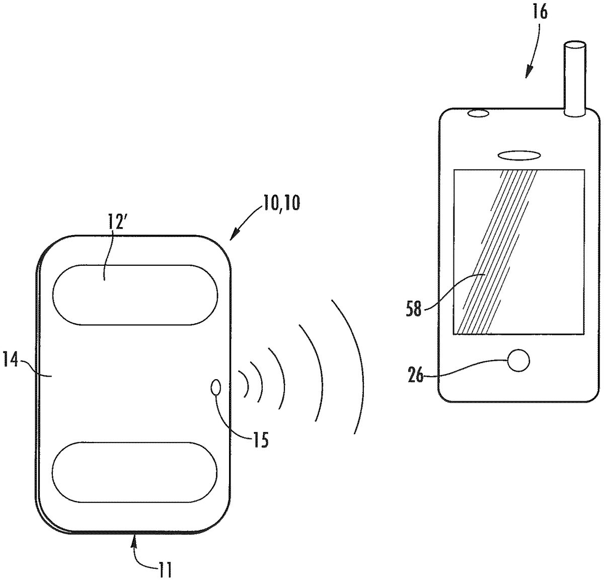
Other embodiments provide a personal monitoring device10, embodiments of which are shown schematically inFIG.4andFIG.5. The acquisition electronics11of the monitoring device10includes a sensor assembly12configured to sense physiological signals upon contact with a user's skin. The sensor assembly12produces electrical signals representing the sensed physiological signals, which input to a converter assembly14, integrated with the sensor assembly12. Converter assembly14converts the electrical signals generated by the sensor assembly12to a frequency modulated ultrasonic signal which is output by ultrasonic transmitter24. In one embodiment, the frequency modulated ultrasonic signal has a carrier frequency in the range of from about 18 kHz to about 24 kHz. In another embodiment, the frequency modulated ultrasonic signal has a carrier frequency in the range of from about 20 kHz to about 24 kHz.
The sensor assembly12can include any suitable sensor operative to detect a physiological signal that a user desires to monitor. Nonlimiting examples of such physiological signals include, but are not limited to, respiration, heart beat, heart rate, electrocardiogram (ECG), electromyogram (EMG), electrooculogram (EOG), pulse oximetry, photoplethysmogram (PPG) and electroencephalogram (EEG).
A respiration detector can be a conventional microphone assisted stethoscope12′. Heart beat and heart rate can be detected as well using a conventional microphone assisted stethoscope12′, or by using an electrode assembly18to sense electrical signals generated by the heart over time. Such electrodes18can also be used to detect the electrical activity of the heart over time for electrocardiograman ECG is a measurement of the small electrical changes on the skin generated when the heart muscle depolarizes during each heart beat. The output from a pair of electrodes18is known as a lead20. Small rises and falls in the voltage between two electrodes placed on either side of the heart can be processed to produce a graphical ECG representation22such as the example ECG shown inFIG.6.
Electromyography (EMG) detects the electrical potential generated by muscle cells when the cells are electrically or neurologically activated. The signals can be analyzed to detect medical abnormalities. Electrooculography (EOG) is a technique for measuring the resting potential of the retina. Usually, pairs of electrodes18are placed either above and below the eye, or to the left and right of the eye, and a potential difference measurement is a measure for the eye position.
The oxygenation of a person's hemoglobin can be monitored indirectly in a noninvasive manner using a pulse oximetry sensor, rather than measuring directly from a blood sample. The sensor is placed on a thin part of the person's body, such as a fingertip or earlobe, and a light containing both red and infrared wavelengths is passed from one side to the other. The change in absorbance of each of the two wavelengths is measured and the difference used to estimate oxygen saturation of a person's blood and changes in blood volume in the skin. A photoplethysmogram (PPG) can then be obtained using the pulse oximeter sensor or with an optical sensor using a single light source. The PPG can be used to measure blood flow and heart rate. An electroencephelogram (EEG) can be monitored using electrodes attached to the scalp and measures voltages generated by brain activity.
The converter assembly14converts the electrical signals generated by the sensor assembly12to a frequency modulated ultrasonic signal that can be received by a computing device16. In the embodiment shown inFIG.5, the converter assembly14includes a converter23and an ultrasonic transmitter24for outputting frequency modulated ultrasonic signals having a carrier frequency in a range of from, for example, about 18 kHz to about 24 kHz. Nonlimiting examples of suitable ultrasonic transmitters24include, but are not limited to, miniature speakers, piezoelectric buzzers, and the like. The ultrasonic signals can be received by, for example, a microphone25in a computing device16such as a smartphone30, personal digital assistant (PDA), tablet personal computer, pocket personal computer, notebook computer, desktop computer, server computer, and the like.
Prior art devices have used frequency modulated physiological signals to communicate between acquisition hardware and a computing device. The signals have a carrier frequency within the audible range such as the traditional 1.9 kHz FM frequency used to transmit ECG signals. However, it has been discovered that by using ultrasonic frequencies as the carrier, such as frequencies in the range of from about 18 kHz to about 24 kHz, and even 20 kHz to 24 kHz, the acoustic communication between the acquisition electronics11of the personal monitoring device10, and a computing device16such as a smartphone, is virtually silent and far more noise-immune than the traditional 1.9 kHz FM ECG frequency. In fact, measurements of the audio signal power in the ultrasonic range determined that carrier frequencies of 17 kHz and higher provide communication that is immune to ambient and voice “noise” contamination. By using an ultrasonic carrier frequency, in even the “noisiest” environment, we create both a noise-free and a silent communication between the acquisition electronics11and the computing device16such as a smartphone30, notebook computer, or the like.
For example,FIG.7Ashows a spectrogram of the sound in a quiet office environment. As can be seen, the ambient noise is about 35 dB at 2 kHz.FIG.7Bshows a spectrogram of the ultrasonic modulated ECG signal in the same quiet office environment. It should be noted that the ambient noise at 19 kHz is only 20 dB (the slight upturn is artifact) giving at least a 15 dB advantage for a 19 kHz ultrasonic signal compared to a standard 2 kHz signal. This is a significant improvement on the signal to noise ratio (SNR) which improves even more in noisy environments such as the street, shopping mall or a noisy home. Synergistically, the volume of the signal can be further increased at the ultrasonic frequencies, without concern for “listeners” present, because they cannot hear it.
In one embodiment, the personal monitoring device10is an ECG device10′ and includes an electrode assembly18configured to sense heart-related signals upon contact with a user's skin, and to convert the sensed heart-related signals to an ECG electric signal. As discussed in detail hereinafter, the ECG device10′ transmits an ultrasonic frequency modulated ECG signal to a computing device16such as, for example, a smartphone30. Software running on the computer16or smartphone30digitizes and processes the audio in real-time, where the frequency modulated ECG signal is demodulated. The ECG can be further processed using algorithms to calculate heart rate and identify arrhythmias. The ECG, heart rate, and rhythm information can be displayed on the computer16or smartphone30, stored locally for later retrieval, and/or transmitted in real-time to a web server52via a 2G/3G/4G, WiFi or other Internet connection. In addition to the display and local processing of the ECG data, the computer16or smartphone30can transmit, in real-time, the ECG, heart rate and rhythm data via a secure web connection for viewing, storage and further analysis via a web browser interface (using the 2G/3G/4G or WiFi connectivity of, for example, the smartphone30). Server software provides for storage, further processing, real-time or retrospective display and formulation of a PDF ECG rhythm strip document and/or other reports and formats for printing remotely or locally.
In another embodiment, the converter assembly14of ECG device10′ is integrated with, and electrically connected to the electrode assembly18and is configured to convert the electric ECG signal generated by electrode assembly18to a frequency modulated ECG ultrasonic signal having a carrier frequency in the range of from about 18 kHz to about 24 kHz. It is sometimes desirable to utilize a carrier frequency in the 20 kHz to 24 kHz range. The ultrasonic range creates both a lower noise and a silent communication between the acquisition electronics11and the computing device16such as the smartphone30, notebook, and the like.
The ECG device10′ can be configured in any way consistent with its function, i.e., it should include electrodes available to make contact with a user's skin on the hands, chest or other parts of the body, for obtaining the user's ECG, and means for transmitting the ECG using ultrasound to a receiving device. For example, a hand held ECG device10′ can be shaped like a credit card as inFIG.5with two electrodes on the bottom surface, or the ECG device10′ can be shaped like a flash light or pen as inFIG.8Ahaving one electrode18on the cylindrical surface57touching a holder's hand, and the other electrode18′ is on an end59contacting the chest, hand or other body part when in use.
In another configuration, the ECG device10′ is usable as a smartphone protective case60as shown inFIG.8B. One example configuration utilizes a “slip-on” protective case60for an iPhone® or other smartphone30, the protective case60including an integrated ECG electrode assembly18and acquisition electronics11(2, 3 or 4 electrodes for generating a single lead of ECG data). The ECG electrodes are located on the side62of the case60opposite of the display screen58. The smartphone30, in its ECG-adapted protective case60, can be held in both hands (generating a lead one, Left Arm minus Right Arm) or can be placed on a person's chest to generate a modified chest lead. The ECG is measured by the acquisition electronics11and converted into a frequency modulated ultrasonic signal. Nonlimiting example of suitable carrier or center frequencies include from about 18 kHz to about 24 kHz, or in some embodiments from about 20 kHz to 24 kHz. The frequency modulated ultrasonic signal is output by a miniature speaker64or a piezoelectric buzzer66.
FIG.9Ashows another embodiment of a credit card like monitoring device100(“credit card sensor”), similar to that depicted as10′ inFIG.5A, for remote or mobile acquisition of ECG data. Some embodiments may have a similar form as a financial bank or credit card, which may have a thickness of approximately 0.75 mm, and may be flexible and made of a plastic or polymer, such as polyvinyl chloride acetate (PVCA). Some embodiments of the credit card sensor have a thickness between 0.65 mm to 0.85 mm, and some between 0.70-0.78 mm. Some embodiments of the credit card sensor may have a range of bending stiffness, and some may meet the standards outlined by ISO 7810 ID-1 format. Embodiments of the credit card like senor may have a bending stiffness or flexibility permitting a user to place it in a purse or wallet in a similar manner to how a normal credit card is stored and carried.
Referring toFIG.9A, a perspective view of an embodiment of credit card sensor100is depicted. Credit card sensor100has a sandwich structure with upper layer102and lower layer104, width a, length b and thickness c.FIG.9Bshows underside103of upper layer102. Underside103has flexible membrane electrodes106, one on each side of credit card sensor100, converter108, battery109, piezo ultrasonic sound emitter110, power button112, and LED indicator114. Battery109powers converter108, which may be a printed circuit board with firmware installed thereon.FIG.9Cdepicts topside101of upper layer102. Topside101has exposed touch pads105that are in electrical contact with flexible membrane electrodes106.
As described herein, a user contacts touch pads105(e.g., left and right fingers) that sense an electric signal for a Lead I ECG. Converter108converts the electrical signals generated from the touch pads105to a frequency modulated signal, for example an ultrasonic signal or Bluetooth signal (further described below), that can be received by a computing device116. In the embodiment shown inFIGS.9A-9C. The converter assembly includes a converter108and an ultrasonic transmitter110for outputting frequency modulated ultrasonic signals having a carrier frequency in a range of from, for example, about 18 kHz to about 24 kHz. The ultrasonic signals can be received by, for example, a microphone in computing device116such as a smartphone (as shown), personal digital assistant (PDA), tablet personal computer, pocket personal computer, notebook computer, desktop computer, server computer, smart watch or wearable, and the like. Computing device116has a microprocessor/CPU (not shown) that may do one or more of the following: acquire, digitize, demodulate, process and then display ECG data in real-time.
In an alternative embodiment, credit card sensor100may have a display (not shown) allowing near real time display of a user's ECG. In this embodiment, for example, credit card sensor100may include a receiver (not shown), which may be included with converter108, that receives the processed ECG signal from the computing device and displays it on a display (not shown) on the credit card sensor100. Alternatively, credit card sensor100may include a processor (not shown), which may be included with converter108having the ability to process and display the signals from touch pads105in a similar manner as the CPU of computing device116. In this embodiment, all connections may be hard wired or wireless. Credit card sensor100may include memory (not shown), which may be part of or separate from converter108, or the processor may include firmware (not shown), where the memory or firmware may include instructions for causing the processor to process the sensed heart-signals (e.g., ECG signals etc.) from a user contacting the touch pads105and displaying the heart-signals on a display (not shown) located on an exterior surface of credit card sensor100. Transmitter110may be used to transmit the processed signal to a computing device, where a medical professional may view the recording. Alternatively, computing device, once in receipt of the data, may send the data to a medical professional using well know communications and data transfer technologies.
In yet another embodiment, shown inFIGS.10(formerly 7 of '042) and11(formerly 8 of '042), converter assembly108includes a wireless radio transmitter37configured to convert and transmit the electrical signals generated by the sensor assembly12using a headset profile (HSP) of the Bluetooth® wireless communications standard is defined by the Bluetooth Special Interest Group (SIG) and available at URL address www.bluetooth.org. The electrical signals generated by the sensor assembly12are converted and transmitted using a Bluetooth® transceiver34and antenna36and communicated to the computing device13, preferably a smartphone30or smart watch, according to instructions provided by a headset controller38. Economy, as well as isolation and convenience, are provided by using a commercially available headset controller38, Bluetooth® transceiver34, and antenna36, powered by a headset battery40, wherein the electronics are commercially configured and mass-produced for communicating with computing devices13such as smartphones30.
Computing device electronics42typically include a controller44, a Bluetooth® transceiver46and antenna48for receiving input from a wireless Bluetooth® device. Most computing devices, and all smartphones and most wearables, include a memory56, a display screen58, and a transceiver50for transmitting/receiving information signals to/from a base station or web server52via a cellular antenna54, or WiFi connection. Thus, the computing device electronics42can be used to store information from the personal monitoring device10in memory56, and/or transmit the information to the base station52or a specific communication address via wireless communication technology well understood by those skilled in the art.
In yet another embodiment, shown schematically inFIG.11, the ECG device10′ is usable as a chest strap device68like a fitness heart rate monitor. The chest strap69with integrated ECG electrode assembly18and acquisition electronics11“pod” generate the frequency modulated ultrasonic ECG signal and send it to a computing device16such as the smartphone30.
In any of the configurations, the computing device16, such as smartphone30, utilizes its built-in microphone25and CPU to acquire, digitize, demodulate, process and then display the ECG data in real-time. Also, the computing device16, smartphone30or smart watch can calculate a real-time heart rate measurement and determine a cardiac rhythm diagnosis like atrial fibrillation. The computing device16or smartphone30can utilize its 2G, 3G, 4G, Bluetooth® and WiFi connectivity to transmit the ECG and other data to a secure web server52for real-time distant display, storage and analysis. Also, the ECG data can be stored locally on the smartphone30for later review or transmission.
Software on the smartphone30can also combine data and signals from other sensors built into the smartphone30such as a GPS and accelerometer. Further processing of this data provides additional information related to the user, such as speed, location, distance, steps, cadence, body position, fall detection and energy expenditure. The raw signals from the sensors and derived information can be displayed and stored locally on the smartphone30, as well as being transmitted to the web server52over an internet connection. Software on the web server52provides a web browser interface for real-time or retrospective display of the signals and information received from the smartphone30, and also includes further analysis and reporting.
Referring now toFIG.12, a computer-readable storage medium56stores a set of instructions72, wherein the instructions72are capable of being executed by one or more computing devices16. Nonlimiting examples of suitable computing devices16include smartphones30, personal digital assistants (PDAs), tablet personal computers, pocket personal computers, notebook computers, desktop computers, and server computers. When the instructions72are executed, the one or more computing devices16is caused to digitize and demodulate a sensor input74such as an ultrasonic frequency modulated ECG signal to produce real-time demodulated digital ECG data. The instructions72can also cause the real-time demodulated digital ECG data to display on a display screen58of the computing device16.
A common technique used for FM demodulation is based on zero crossing detection where the time interval between zero crossings is used to calculate the frequency and reconstruct the demodulated signal. In some applications simply counting the number of audio samples between zero crossings may provide sufficient accuracy for frequency estimation. Accuracy can be improved by interpolating between samples which provides a better estimate of the zero crossing point and subsequent frequency estimation. FM demodulation based on zero crossing detection is simple to implement and requires little computation compared with other techniques such as those using FFT's (fast Fourier transforms), making it particularly suitable for use in real-time applications on low power portable computing devices.
However, if the FM narrow band signal is close to the Nyquist frequency of the digitally sampled audio, the error in the zero crossing estimates become large, as there are very few samples per cycle. This severely limits the use of typical zero crossing demodulation techniques for ultrasonic carrier frequencies. An embodiment of the present disclosure provides a method to demodulate FM narrow band signals close to the Nyquist frequency, while maintaining the simplicity and efficiency of the zero crossing technique, with accurate frequency estimation.
Referring now toFIG.13, an ultrasonic FM signal representing ECG signals is picked up by a microphone25in, for example, a mobile phone30or other computing device16, and converted to an analog signal. The analog signal is continuous in time and is converted to a flow of digital values in an analog-to-digital converter80, demodulated in FM demodulator82and shown on a display58of the smart phone30or other computing device16, or retained in storage memory56. Since a practical analog-to-digital converter80, commonly referred to as an ADC, cannot make an instantaneous conversion, the input value must necessarily be held constant during the time that the converter performs a conversion. The rate at which the new digital values are sampled from the analog signal is called the sampling rate or sampling frequency of the ADC. Mobile phones and other personal computing devices are typically limited to recording audio at 44 kHz. Some smart phones such as ANDROID® and IPHONE® can sample at 48 KHz.
The digitized ultrasonic signal can then be bandpass filtered around the ultrasonic carrier frequency of the FM signal to improve signal-to-noise and reduce unwanted audio outside the passband. The filtered FM signal, as depicted inFIG.14, is then “under-sampled” at half the sampling rate of the original audio. This results in aliasing of the FM signal that shifts and inverts the frequency spectrum to a lower frequency band. The result of the frequency spectrum being inverted by the under-sampling operation, results in the demodulated output being inverted as depicted inFIG.15. The inversion is corrected by simply converting the final demodulated output.
With the FM signal at a lower frequency there are more audio samples per cycle and demodulation processes, such as zero crossing estimates, are significantly more accurate. For example, the zero crossing detector identifies the zero crossings where the audio signal changes sign. The accuracy of the zero crossing point is further improved by linearly interpolating between samples either side of the zero crossing. Finally, the period between zero crossings is used to calculate an estimate of the frequency and reconstruct the demodulated signal. While the above-described demodulation procedure utilizes a zero crossing estimate, it is understood that other demodulation procedures can be utilized and that the accuracy of other demodulation procedures will also benefit from the under-sampling operation.
Example
In one working example, illustrated inFIG.16, a system used an ultrasonic FM ECG signal transmitted from a portable ECG monitor to a microphone25in a mobile phone30as well as a personal computer16. This provided a low-cost wireless transmission solution that is compatible with most mobile phones and computers that have a microphone, without requiring any additional hardware to receive the signal.
It is desirable that the FM signal is above 18 kHz, so that it is inaudible to most people, does not interfere with music or speech, and is also less prone to audio interference. It is also desirable for the FM signal to have a narrow bandwidth to further reduce its susceptibility to audio interference. In this case the ECG monitor used an ultrasonic FM carrier of 19 kHz, modulated with an ECG at 200 Hz/mV and having a range of +5 mV. This resulted in an ultrasonic FM signal between 18 kHz and 20 kHz.
First, the audio FM signal was picked up by a microphone25and digitized by the ADC80in the mobile phone30at 44 kHz. The audio was then bandpass filtered in filter82between 18 kHz and 20 kHz to remove audio noise outside the pass band. In the next stage84the audio was under-sampled at 22 kHz, where only every second audio sample is used. The digital signal produced after such under-sampling results in aliasing that shifts and inverts the frequency spectrum so that it appears in the 2 kHz to 4 kHz range. A zero crossings detector86then identifies where the audio signal changes sign. The zero crossing point is then more accurately calculated in the frequency estimation step88by linearly interpolating between samples either side of the zero crossing. In this example, a frequency estimate is only required every 3.33 ms, for it demodulated output signal at 300 Hz. This is achieved by counting the number of zero crossings and measuring the period over the nearest fixed number of cycles during this period, providing a fixed 300 Hz output. The demodulated output is then inverted to correct for the frequency spectrum being inverted by the under-sampling operation. Finally, the 300 Hz demodulated ECG data is passed through a 40 Hz low pass filter since the ECG bandwidth of interest is below 40 Hz. This further reduces any noise from the frequency estimates and demodulated output. The FM demodulator outputs 16 bit, 300 Hz ECG.
Sensor input74can also include real-time information from additional sensors as well as user input74′. For example, in embodiments wherein the computing device16is a smartphone30, the input74can include real-time information from a GPS and/or accelerometer in the smartphone30in addition to the demodulated digital ECG data. User input74′ can also include spoken voice messages entered through a microphone of the computing device16. Instructions72can cause the sensor and/or user input74and74′ to be recorded and maintained in a storage memory56of the computing device16.
In one embodiment, the set of instructions72, when executed by the one or more computing devices16, can further cause the one or more computing devices16to calculate and display in real-time, a heart rate represented by the frequency modulated ECG ultrasonic signal. In addition, demodulated digital ECG data can be processed to identify the occurrence of an arrhythmia. In such designs, the storage medium70can include instructions72to cause the computing device16to display a warning on a display screen58or emit an audible alert through the speaker76at the occurrence of an arrhythmia.
Instructions72can cause the computing device16to store the demodulated digital ECG data in a memory56of the one or more computing devices16for later retrieval. The set of instructions72can further cause the one or more computing devices16to retrieve and transmit, upon demand, the stored demodulated digital ECG data to a web server52via an internet connection on the computing device16. Recorded spoken voice messages can be stored and transmitted to the web server52, simultaneously with the demodulated digital ECG data.
In other embodiments, the instructions72can cause the one or more computing devices16to transmit the demodulated digital ECG data, and/or voice messages, to the web server52in real-time.
A version of the smartphone software is packaged as a software library that can be integrated with other third party software applications. This provides a simplified and standard method for third party applications to use the ECG device10′ to obtain heart rate and other derived information without having to develop their own data acquisition, demodulation, and signal processing algorithms.
A version of the software also runs on a PC and includes demodulation, processing, storage and transmission to the web server52. The software includes the audio acquisition, demodulation, ECG analysis, and acceleration analysis modules.
Audio samples from the ADC are optionally passed through a digital band-pass filter to remove unwanted frequencies outside the modulation range. The demodulation module demodulates the frequency modulated ECG ultrasonic signal using undersampling at about one-half the frequency of the audio sample to shift the spectrum to a lower frequency range, followed by a linear approximation and zero crossings algorithm. The demodulator allows selection of different modulation parameters to match the particular ECG device. While demodulation using zero crossings and linear approximation alone works well for carrier frequencies 6 kHz and lower, above 10 kHz with 44 kHz sampling, the errors from linear approximation become large unless undersampling is used to shift the spectrum.
The algorithm then looks at the sign of incoming data. When the sign changes it draws a straight line between the two points and interpolates the zero value. It uses this to determine the average frequency over a 3.333 ms interval, which provides ECG data at the output sampling rate of 300 Hz.
The ECG analysis module includes algorithms that process the ECG to detect and classify beats, and provides a heart rate estimate. Beat-to-beat heart rate is calculated from the interval between beats and a more robust measurement of heart rate is calculated using median filtering of the RR intervals.
The acceleration analysis module includes algorithms that process signals from the built-in 3 axis accelerometer sensor in the smartphone30, to derive an estimate of a person's energy expenditure, steps, cadence, and body position and to detect falls.
In some embodiments, the ECG device10′ may be implemented as a controller, which may be any appropriate device that communicates with and/or controls other computing devices. Examples of a controller may include a television remote control, a computer mouse, a keyboard, and bicycle handlebars. In one example, the controller may be a steering wheel that may communicate with/control e.g., an electronic control unit (ECU) or other on-board computing device of a vehicle.FIG.17illustrates an example in which a controller170may be a video game controller for controlling/utilizing computing device180(which may be a video game console in this example). It should be noted that computing device180may be similar to computing device16described herein. The controller170may include an electrode assembly171(as illustrated inFIG.18B) which comprises a set of electrodes to sense electrical signals corresponding to electrical activity of the heart of the user over time and output the electrical signals (e.g., perform an ECG). For example, in response to the user grasping the hand grips of the controller170, the electrode assembly171may begin performing an ECG of the user. The controller170may further include a converter assembly172(as illustrated inFIG.19) to convert the electrical signals output by electrode assembly171to a frequency modulated signal (as discussed in further detail herein). The electrode assembly171may be similar to the electrode assembly18(illustrated inFIG.5) and the converter assembly172may be similar to the converter assembly14or108(illustrated inFIGS.5and9Arespectively).
The converter assembly172may comprise a converter173to convert the electrical signals measured by electrode assembly171to a frequency modulated signal and a transmitter174to transmit the modulated signal to the computing device180. In some embodiments, the transmitter174may be an ultrasonic transmitter that may transmit the modulated signal as an audio signal to the computing device180as discussed in further detail herein. In other embodiments, the transmitter174may be a Bluetooth transmitter to transmit the modulated signal as a Bluetooth signal to the computing device. In some embodiments, in addition to or as an alternative to the transmitter174, the controller170may include a wireless transmitter175(shown inFIG.19) that is coupled to the converter assembly172. The controller170may be communicatively coupled to the computing device180via network176and may transmit the modulated signal to the computing device180via network176using the wireless transmitter175.
Network176may be a public network (e.g., the internet), a private network (e.g., a local area network (LAN) or wide area network (WAN)), or a combination thereof. In one embodiment, network176may include a wired or a wireless infrastructure, which may be provided by one or more wireless communications systems, such as a Wi-Fi hotspot connected with the network176and/or a wireless carrier system that can be implemented using various data processing equipment, communication towers (e.g. cell towers), etc. In some embodiments, the network176may be an L3 network. The network176may carry communications (e.g., data, message, packets, frames, etc.) between the controller170and computing device180.
In other embodiments, the controller170may be coupled to the computing device116via a cable179, implementing any appropriate transmission protocol such as e.g., the USB™ protocol, and may transmit the modulated signal to the computing device180via the cable179. The computing device180may include a receiver (not shown) for receiving the modulated signal, as well as a microprocessor/CPU (not shown) that may acquire, digitize, demodulate, and process the modulated signal to generate ECG data. Once the modulated signal is converted into ECG data, it can be displayed in real-time on a monitor181connected to the computing device180. The ECG data can be displayed during use of the controller170as long as the user is contacting the electrode assembly171. The computing device180may also analyze the ECG data to determine whether the user is experiencing a heart condition such as arrhythmia, bradycardia, and tachycardia, for example. The computing device180may utilize any of a number of appropriate algorithms for making this determination. In response to determining that the user is experiencing any of the above heart conditions, the computing device180may display an alert to the user, and take other actions such as notify a physician of the user, or stop a video game in progress (e.g., when the controller170is a video game controller), or instruct the user to pull over the side of the road (e.g., when the controller170is a steering wheel).
In some embodiments, the computing device180may include an application (not shown) to allow the ECG data to be displayed and evaluated in real-time directly on the computing device180. For example, ECG data can be reviewed in the application once uploaded and the application may allow the console to show users their heart rate and rhythm information onscreen during gameplay or on demand. The application may handle performance of other functions as well such as e.g., analyzing the ECG data to determine whether the user is experiencing a heart condition, displaying an on-screen alert to the user in response to determining that the user is experiencing any of the above heart conditions, and/or notify a physician of the user in response to determining that the user is experiencing any of the above heart conditions, etc.
In some embodiments, the computing device180may utilize the ECG data to control aspects of a video game being played by the user. For example, the computing device180may utilize the ECG data to control aspects of the video game such as movement of characters within the video game. More specifically, the user's video game character may move slowly when the user's heart rate is low, but may move more quickly when the user's heart rate is high. If the user's heart rate has been high for a particular period of time, the character may gradually begin to slow down/become increasingly fatigued. In other examples, the user's video game character may be visibly nervous/upset/anxious when the user's heart rate accelerates. Other aspects of the video game may also be affected. For example, the music of the video game may speed up as the ECG data indicates the user's heart rate increasing and may slow down as the ECG data indicates the user's heart rate decreasing.
FIG.18Adisplays the top view of the exterior surface (i.e., displays a top portion of the exterior surface) of the controller170where the buttons177and joysticks178used to provide signals to control the computing device180(e.g., play a game on the gaming console180) are located.FIG.18Bdisplays the bottom view of the exterior surface (i.e., displays a bottom portion of the exterior surface) of the controller170. As illustrated inFIG.18B, the electrode assembly171may comprise a set of electrodes271(e.g.,271A and271B) located on the bottom portion of the exterior surface, and more specifically, on the bottom of the hand grips of the controller170. When the user is using the controller170to operate the computing device180(e.g., play a video game), the user's skin may maintain contact with the electrodes271A and271B which allows for electrical signals corresponding to electrical activity of the user's heart to be recorded. As shown inFIG.18B, the electrode assembly171may include two electrodes271A and271B, providing a single lead ECG measurement. The electrodes271may be integrated to the controller170using any appropriate means. For example, the electrodes271may be made of conductive metal (e.g., stainless steel) that is attached to the exterior surface of the controller170. In other examples, the electrodes271may be fabricated using conductive ink, which is then deposited onto the exterior surface of the controller170. The conductive ink may be deposited onto the exterior surface of the controller170in such a fashion that the user is not aware of the presence of the electrodes271during operation of the controller170. Although illustrated as located on the bottom portion of the exterior surface, the electrodes271may be positioned at any appropriate position where the user's hands will be relatively stable, and minimize motion artifacts caused by muscular movement (e.g., joysticks178). It should be noted that although illustrated on the external surface of the controller170, the electrode assembly171may include components that are located both on the exterior surface and the interior of the controller170.
Although illustrated inFIG.18Bas having two electrodes271A and271B, the controller170(and, more specifically the electrode assembly171) may comprise any appropriate number of electrodes271. In some embodiments, the electrode assembly171may comprise three electrodes271. The third electrode271may be located e.g., in the center of the bottom portion of the exterior surface of the controller170, where it may make contact with the left leg, right leg, or any appropriate extremity/contact point on the left or right side of the body of the user. In this way, the third electrode271C may provide a third contact point thereby allowing additional leads to be measured when taking an ECG. This may result in increased accuracy when taking the ECG.
FIG.18Cillustrates a side view of the controller170in order to distinguish where the top and the bottom portions of the exterior surface of the controller170start and end. This view of the controller170shows the top part of the exterior surface of the controller170where the buttons177and joysticks178used to control the computing device180(e.g., play a game on the gaming console180) are located.FIG.18Calso illustrates the bottom portion of the exterior surface of the gaming controller170where the electrode assembly171is located.
FIG.19illustrates an internal view of the gaming controller170, including a hardware block diagram of the electrode assembly171(e.g., the internal portions thereof) and the converter assembly172. As shown, the electrode assembly171further comprises flexible membrane pads371A and371B positioned within the hand grips, for example. Each flexible membrane pad371may be positioned under a corresponding electrode271. In some embodiments, each flexible membrane pad371may be positioned directly under a corresponding electrode271, while in other embodiments, the position of each flexible membrane pad371may be offset from the position of the corresponding electrode271. Each flexible membrane pad371may be electrically connected to a corresponding electrode271and may receive the electrical signals sensed by the corresponding electrode271. Each flexible membrane pad371may also be electrically coupled to the converter assembly172and may transmit the electrical signals sensed by the corresponding electrode271to the converter assembly172The converter assembly172may comprise a converter172A to convert the electrical signals measured by the electrode assembly171into a modulated signal and a transmitter172B. The transmitter172B may output the modulated signal to the computing device180e.g., as an audio signal or Bluetooth signal. In some embodiments, the converter assembly172may provide the modulated signal to the wireless transmitter175which may transmit the modulated signal via network170to the computing device180. Alternatively, the converter assembly172may transmit the modulated signal to the computing device180via cable179.
In some embodiments, the controller170may further comprise one or more PPG sensors183to measure PPG signals corresponding to additional health parameters of the user. Each PPG sensor183may be positioned on any appropriate location of the controller170.FIG.20illustrates an embodiment of the present disclosure wherein a PPG sensor183is positioned on the top side of a joystick178B on the controller170. The PPG sensor183may comprise one or more light sources184(e.g., LEDs, photodiodes) and a photodetector185. When the user places their fingertip (or any appropriate appendage) on the joystick178, various additional health parameters of the user can be monitored indirectly in a noninvasive manner by passing, using the light sources184, light (e.g., containing both red and infrared wavelengths) from one side of the user's fingertip to the other. The photodetector185may measure the change in absorbance of each of the two wavelengths and the difference may be used to estimate various additional health parameters such as the user's blood flow, heart rate, oxygen saturation of the user's blood, and changes in the blood volume in the user's skin. The PPG sensor183detect PPG signals corresponding to the change in absorbance of each of the two wavelengths and may output an electrical PPG signal representing the change in absorbance of each of the two wavelengths. Although discussed in terms of red and infrared wavelengths, light containing any combination of appropriate wavelengths may be used. The PPG sensor183may be electrically coupled to the converter assembly172and may output the electrical PPG signal to the converter assembly172. The converter assembly172may convert the electrical PPG signal to a modulated PPG signal which is then output to the computing device180by the transmitter172B. In some embodiments, the converter assembly172may output the modulated PPG signal to the wireless transmitter175which may transmit the modulated PPG signal to the computing device180via network176. The computing device180may acquire, digitize, demodulate, and process the modulated PPG signal to determine the additional health parameters and display them as discussed herein.
The controller170may include other hardware such as processing device190(e.g., processors, central processing units (CPUs)) and memory195(e.g., random access memory (RAM), storage devices (e.g., hard-disk drive (HDD), solid-state drive (SSD), etc.)), and other hardware devices (e.g., sound card, video card, etc.). The memory195may store a health analysis module195A which may be executed by the processing device190in order to instruct each of the other components of controller170to perform their functions as described herein. Although illustrated as separate components, in some embodiments the processing device190and the memory195may be part of one of the other components of controller170, such as the converter assembly172.
FIG.21illustrates another embodiment of the present disclosure where the controller170is implemented as a steering wheel of a vehicle which may control/communicate with computing device180which may be e.g., an on board computer within the vehicle (not shown in the FIGS). The electrode assembly171may be implemented on the top portion of the exterior surface of the controller170. The electrode assembly171may comprise the set of electrodes271, each of which may be placed at locations on the exterior surface of the controller170where the user's hands will be relatively stable, and minimize motion artifacts caused by muscular movement. The positioning of the electrodes271may also account for places where the user is likely to position her/her hands while driving, for example at the “10 o'clock” and “2 o'clock” positions. As shown in the example ofFIG.21, the controller170may comprise two electrodes271A and271B that are placed on its right and left side (i.e., the right and left side of the steering wheel (e.g., at the 90 and 270 degree positions respectively). The electrode assembly171may further comprise the set of flexible membrane pads371located on the interior of the controller170. In some embodiments, each flexible membrane pad371may be positioned directly under a corresponding electrode271, while in other embodiments, the position of each flexible membrane pad371may be offset from the position of the corresponding electrode271. The electrode assembly171(more specifically, the flexible membrane pads371) may be electrically coupled to the converter assembly172which comprises the converter172A and the transmitter172B. The electrode assembly171and the converter assembly172may function as described herein (e.g., with respect toFIGS.4-6,17,18A-C, and19). In some embodiments, the controller170may further comprise one or more PPG sensors183to measure PPG signals corresponding to additional health parameters of the user as discussed above.
Continuing to refer toFIG.21, in some embodiments the computing device180is an ECU or other onboard computing device of the vehicle, which can be partially or fully internal to the vehicle. The computing device180may include a receiver (not shown) for receiving the modulated signal, as well as a microprocessor/CPU (not shown) that may acquire, digitize, demodulate, and process the modulated signal to generate ECG data. The computing device180may include a display (not shown) to display the ECG data in real-time. Alternatively, the computing device180may be coupled to a display/monitor (not shown) which may be integrated into the dashboard of the vehicle, for example, and the ECG data can be displayed on the monitor. In some embodiments, the display may be a peripheral component that can be coupled to the computing device180.
FIG.22is a block diagram of an example computing device2200that may perform one or more of the operations described herein. Computing device2200may be connected to other computing devices in a LAN, an intranet, an extranet, and/or the Internet. The computing device may operate in the capacity of a server machine in client-server network environment or in the capacity of a client in a peer-to-peer network environment. The computing device may be provided by a personal computer (PC), a set-top box (STB), a server, a network router, switch or bridge, or any machine capable of executing a set of instructions (sequential or otherwise) that specify actions to be taken by that machine. Further, while only a single computing device is illustrated, the term “computing device” shall also be taken to include any collection of computing devices that individually or jointly execute a set (or multiple sets) of instructions to perform the methods discussed herein.
The example computing device2200may include a processing device (e.g., a general purpose processor, a PLD, etc.)2202, a main memory2204(e.g., synchronous dynamic random access memory (DRAM), read-only memory (ROM)), a static memory2206(e.g., flash memory and a data storage device2218), which may communicate with each other via a bus2230.
Processing device2202may be provided by one or more general-purpose processing devices such as a microprocessor, central processing unit, or the like. In an illustrative example, processing device2202may comprise a complex instruction set computing (CISC) microprocessor, reduced instruction set computing (RISC) microprocessor, very long instruction word (VLIW) microprocessor, or a processor implementing other instruction sets or processors implementing a combination of instruction sets. Processing device2202may also comprise one or more special-purpose processing devices such as an application specific integrated circuit (ASIC), a field programmable gate array (FPGA), a digital signal processor (DSP), network processor, or the like. The processing device2202may be configured to execute the operations described herein, in accordance with one or more aspects of the present disclosure, for performing the operations and steps discussed herein.
Computing device2200may further include a network interface device2208which may communicate with a network2220. The computing device2200also may include a video display unit2210(e.g., a liquid crystal display (LCD) or a cathode ray tube (CRT)), an alphanumeric input device2212(e.g., a keyboard), a cursor control device2214(e.g., a mouse) and an acoustic signal generation device22122(e.g., a speaker). In one embodiment, video display unit2210, alphanumeric input device2212, and cursor control device2214may be combined into a single component or device (e.g., an LCD touch screen).
Data storage device2218may include a computer-readable storage medium2228on which may be stored one or more sets of health analysis instructions2225, e.g., instructions for carrying out the operations described herein, in accordance with one or more aspects of the present disclosure. Health analysis instructions2225may also reside, completely or at least partially, within main memory2204and/or within processing device2202during execution thereof by computing device2200, main memory2204and processing device2202also constituting computer-readable media. The health analysis instructions2225may further be transmitted or received over a network2220via network interface device2208.
While computer-readable storage medium2228is shown in an illustrative example to be a single medium, the term “computer-readable storage medium” should be taken to include a single medium or multiple media (e.g., a centralized or distributed database and/or associated caches and servers) that store the one or more sets of instructions. The term “computer-readable storage medium” shall also be taken to include any medium that is capable of storing, encoding or carrying a set of instructions for execution by the machine and that cause the machine to perform the methods described herein. The term “computer-readable storage medium” shall accordingly be taken to include, but not be limited to, solid-state memories, optical media and magnetic media.
The preceding description sets forth numerous specific details such as examples of specific systems, components, methods, and so forth, in order to provide a good understanding of several embodiments of the present disclosure. It will be apparent to one skilled in the art, however, that at least some embodiments of the present disclosure may be practiced without these specific details. In other instances, well-known components or methods are not described in detail or are presented in simple block diagram format in order to avoid unnecessarily obscuring the present disclosure. Thus, the specific details set forth are merely exemplary. Particular embodiments may vary from these exemplary details and still be contemplated to be within the scope of the present disclosure.
Additionally, some embodiments may be practiced in distributed computing environments where the machine-readable medium is stored on and or executed by more than one computer system. In addition, the information transferred between computer systems may either be pulled or pushed across the communication medium connecting the computer systems.
Embodiments of the claimed subject matter include, but are not limited to, various operations described herein. These operations may be performed by hardware components, software, firmware, or a combination thereof.
Although the operations of the methods herein are shown and described in a particular order, the order of the operations of each method may be altered so that certain operations may be performed in an inverse order or so that certain operation may be performed, at least in part, concurrently with other operations. In another embodiment, instructions or sub-operations of distinct operations may be in an intermittent or alternating manner.
The above description of illustrated implementations of the invention, including what is described in the Abstract, is not intended to be exhaustive or to limit the invention to the precise forms disclosed. While specific implementations of, and examples for, the invention are described herein for illustrative purposes, various equivalent modifications are possible within the scope of the invention, as those skilled in the relevant art will recognize. The words “example” or “exemplary” are used herein to mean serving as an example, instance, or illustration. Any aspect or design described herein as “example” or “exemplary” is not necessarily to be construed as preferred or advantageous over other aspects or designs. Rather, use of the words “example” or “exemplary” is intended to present concepts in a concrete fashion. As used in this application, the term “or” is intended to mean an inclusive “or” rather than an exclusive “or”. That is, unless specified otherwise, or clear from context, “X includes A or B” is intended to mean any of the natural inclusive permutations. That is, if X includes A; X includes B; or X includes both A and B, then “X includes A or B” is satisfied under any of the foregoing instances. In addition, the articles “a” and “an” as used in this application and the appended claims should generally be construed to mean “one or more” unless specified otherwise or clear from context to be directed to a singular form. Moreover, use of the term “an embodiment” or “one embodiment” or “an implementation” or “one implementation” throughout is not intended to mean the same embodiment or implementation unless described as such. Furthermore, the terms “first,” “second,” “third,” “fourth,” etc. as used herein are meant as labels to distinguish among different elements and may not necessarily have an ordinal meaning according to their numerical designation.
It will be appreciated that variants of the above-disclosed and other features and functions, or alternatives thereof, may be combined into may other different systems or applications. Various presently unforeseen or unanticipated alternatives, modifications, variations, or improvements therein may be subsequently made by those skilled in the art which are also intended to be encompassed by the following claims. The claims may encompass embodiments in hardware, software, or a combination thereof.
Claims
- A system comprising: a video game controller comprising: an electrode assembly comprising: a set of electrodes to sense an electrical signal corresponding to heart activity of a user when in contact with skin of the user and output the electrical signal;and a set of conductive flexible membranes, each conductive flexible membrane operatively coupled to a corresponding electrode of the set of electrodes;a converter assembly operatively coupled to the electrode assembly, the converter assembly to convert, by a processing device, the electrical signal to a modulated signal, wherein the modulated signal carries the electrical signal, wherein each conductive flexible membrane is also operatively coupled to the converter assembly;and a transmitter to transmit the modulated signal;and a computing device to receive the modulated signal and determine whether the electrical signal indicates that the user is experiencing a heart condition.
- The system of claim 1, wherein the computing device is further to: process the modulated signal to generate ECG data of the user;and display the ECG data.
- The system of claim 1, wherein a first electrode and a second electrode of the set of electrodes are positioned on an area of a bottom portion of an exterior surface of the video game controller where motion artifacts caused by muscular movement of the user while using the video game controller are minimized.
- The system of claim 3, wherein a third electrode of the set of electrodes is positioned on the bottom portion of the exterior surface to provide additional leads for detecting the electrical signal.
- The system of claim 1, wherein each of the set of electrodes comprises a conductive metal attached to an external surface of the video game controller.
- The system of claim 1, wherein each of the set of electrodes comprises a conductive ink that is deposited onto an external surface of the video game controller.
- The system of claim 1, wherein the video game controller further comprises: one or more photoplethysmogram (PPG) sensors to detect a PPG signal corresponding to additional health-related parameters of the user and produce an electrical PPG signal representing the detected PPG signal, wherein the controller modulates the electrical PPG signal to generate a modulated PPG signal and transmits the modulated PPG signal to the computing device.
- The system of claim 7, wherein the computing device is further to: process the modulated PPG signal to determine the additional health related parameters of the user, the additional health-related parameters including a blood flow of the user, a heart rate of the user, a blood oxygen saturation of the user, and a change in blood volume in the skin of the user.
- The system of claim 2, wherein the computing device is further to: modify operation of a video game based on the ECG data.
- The system of claim 9, wherein to modify the operation of the video game, the computing device is to alter a behavior of a character of the video game based on the ECG data.
- The system of claim 9, wherein to modify the operation of the video game, the computing device is to alter music of the video game based on the ECG data.
- An apparatus comprising: a video game controller;an electrode assembly integrated within the video game controller, the electrode assembly comprising a set of electrodes to sense an electrical signal corresponding to heart activity of a user when in contact with skin of the user and output the electrical signal, and wherein each of the set of electrodes comprises a conductive metal attached to an external surface of the video game controller;a converter assembly integrated within the video game controller and operatively coupled to the electrode assembly, the converter assembly to convert, by a processing device, the electrical signal to a modulated signal, wherein the modulated signal carries the electrical signal;and a transmitter integrated into the video game controller, the transmitter to transmit the modulated signal.
- The apparatus of claim 12, wherein the electrode assembly further comprises a set of conductive flexible membranes, each conductive flexible membrane operatively coupled to a corresponding electrode of the set of electrodes and operatively coupled to the converter assembly.
- The apparatus of claim 13, wherein a first electrode and a second electrode of the set of electrodes are positioned on an area of a bottom portion of an exterior surface of the video game controller where motion artifacts caused by muscular movement of the user while using the video game controller are minimized.
- The apparatus of claim 14, wherein a third electrode of the set of electrodes is positioned on the bottom portion of the exterior surface to provide additional leads for detecting the electrical signal.
- The apparatus of claim 12, wherein each of the set of electrodes comprises a conductive ink that is deposited onto an external surface of the video game controller.
- The apparatus of claim 12, further comprising: one or more photoplethysmogram (PPG) sensors to detect a PPG signal corresponding to additional health-related parameters of the user and produce an electrical PPG signal representing the detected PPG signal, wherein the video game controller modulates the electrical PPG signal to generate a modulated PPG signal and transmits the modulated PPG signal to the computing device.
- The apparatus of claim 17, wherein the additional health-related parameters include a blood flow of the user, a heart rate of the user, a blood oxygen saturation of the user, and a change in blood volume in the skin of the user.
Disclaimer: Data collected from the USPTO and may be malformed, incomplete, and/or otherwise inaccurate.