U.S. Pat. No. 12,106,638
DIGITAL DATA OBJECT SYSTEM FOR ONLINE GAMING
AssigneeLotto.com Inc.
Issue DateMay 24, 2024
Illustrative Figure
Abstract
A computing system receives a request to create a digital data object from a user device of a user for use in a game. The computing system generates the digital data object based on the request. The computing system causes a physical data object corresponding to the digital data object to be activated. The computing system receives a plurality of scanned images of the physical data object. The computing system receives an indication of an outcome of the game based on the physical data object. Based on the indication and the plurality of scanned images, the computing system generates a set of graphical objects to be displayed to the user via the user device of the user. The computing system causes the user to participate in the game using the set of graphical objects.
Description
To facilitate understanding, identical reference numerals have been used, where possible, to designate identical elements that are common to the figures. It is contemplated that elements disclosed in an embodiment may be beneficially utilized on other embodiments without specific recitation. DETAILED DESCRIPTION Embodiments disclosed herein generally relate to a system and method for generating a digital data object (i.e., graphical object) corresponding to a physical data object. With the ever increasing reliance on computers and mobile devices, companies have turned to digital platforms for delivering their offerings to end users. While most companies are able to perform this migration seamlessly, for other companies, such as those involved in state lotteries, the adoption of a digital platform is not as trivial. These companies typically have to satisfy the various guidelines and laws of their states in order to provide end users with some form of a digital or mobile experience. One of the more popular lottery games is what is referred to as a “scratch-off” lottery game. As those skilled in the art understand, a scratch-off lottery game is one in which a user scratches or otherwise removes a top layer of a scratch-off lottery ticket to reveal one or more letters, numbers, and symbols to determine if the user won a prize. Conventionally, entities involved in the sale or delivery of scratch-off lottery tickets are limited to only allowing end users to remotely purchase scratch-off tickets, which may then be physically mailed to the address of the user. As those skilled in the art understand, this places a burden on both the user and the state approved facility to physically deliver scratch-off tickets, and necessarily requires the recipient to return to the physical store in the event of a winning occurrence, thus reducing the number of interested parties participating in ...
To facilitate understanding, identical reference numerals have been used, where possible, to designate identical elements that are common to the figures. It is contemplated that elements disclosed in an embodiment may be beneficially utilized on other embodiments without specific recitation.
DETAILED DESCRIPTION
Embodiments disclosed herein generally relate to a system and method for generating a digital data object (i.e., graphical object) corresponding to a physical data object. With the ever increasing reliance on computers and mobile devices, companies have turned to digital platforms for delivering their offerings to end users. While most companies are able to perform this migration seamlessly, for other companies, such as those involved in state lotteries, the adoption of a digital platform is not as trivial. These companies typically have to satisfy the various guidelines and laws of their states in order to provide end users with some form of a digital or mobile experience. One of the more popular lottery games is what is referred to as a “scratch-off” lottery game. As those skilled in the art understand, a scratch-off lottery game is one in which a user scratches or otherwise removes a top layer of a scratch-off lottery ticket to reveal one or more letters, numbers, and symbols to determine if the user won a prize. Conventionally, entities involved in the sale or delivery of scratch-off lottery tickets are limited to only allowing end users to remotely purchase scratch-off tickets, which may then be physically mailed to the address of the user. As those skilled in the art understand, this places a burden on both the user and the state approved facility to physically deliver scratch-off tickets, and necessarily requires the recipient to return to the physical store in the event of a winning occurrence, thus reducing the number of interested parties participating in the game.
One or more techniques described herein eliminates this burden on potential participants by providing a means to satisfy the guidelines of the state. For example, one or more techniques described herein utilize digital data objects that are linked to physical data objects (e.g., official state lottery physical scratch-off tickets) for remote or online participation in the game.
The term “user” as used herein includes, for example, a person or entity that owns a computing device or wireless device; a person or entity that operates or utilizes a computing device or wireless device; or a person or entity that is otherwise associated with a computing device or wireless device. It is contemplated that the term “user” is not intended to be limiting and may include various examples beyond those described.
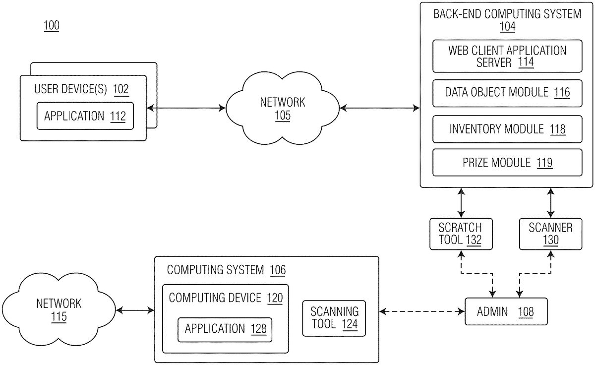
FIG.1is a block diagram illustrating computing environment100, according to example embodiments. Computing environment100may include at least one or more user devices102, a back-end computing system104, and computing system106. In some embodiments, one or more user devices102and back-end computing system104may communicate via network105.
Network105may be of any suitable type, including individual connections via the Internet, such as cellular or Wi-Fi networks. In some embodiments, network105may connect terminals, services, and mobile devices using direct connections, such as radio frequency identification (RFID), near-field communication (NFC), Bluetooth™, low-energy Bluetooth™ (BLE), Wi-Fi™, ZigBee™, ambient backscatter communication (ABC) protocols, USB, WAN, or LAN. Because the information transmitted may be personal or confidential, security concerns may dictate one or more of these types of connection be encrypted or otherwise secured. In some embodiments, however, the information being transmitted may be less personal, and therefore, the network connections may be selected for convenience over security.
Network105may include any type of computer networking arrangement used to exchange data. For example, network105may be the Internet, a private data network, virtual private network using a public network and/or other suitable connection(s) that enables components in computing environment100to send and receive information between the components of computing environment100.
User device102may be operated by a user. In some embodiments, user device102may be operated by a user seeking to purchase a scratch-off lottery ticket from back-end computing system104. User device102may be representative of a mobile device, a tablet, a desktop computer, or any computing system having the capabilities described herein. User device102may include at least application112. Application112may be representative of an application associated with back-end computing system104. In some embodiments, application112may be a standalone application associated with back-end computing system104. In some embodiments, application112may be representative of a web-browser configured to communicate with back-end computing system104. In some embodiments, user device102may communicate over network105to request a webpage, for example, from web client application server114of back-end computing system104. For example, user device102may be configured to execute application112to participate in a game (e.g., participate in a scratch-off lottery ticket). The content that is displayed to user device102may be transmitted from web client application server114to user device102, and subsequently processed by application112for display through a graphical user interface (GUI) of user device102.
Back-end computing system104may include web client application server114, data object module116, inventory module118, and prize module119. Each of data object module116, inventory module118, and prize module119may be comprised of one or more software modules. The one or more software modules are collections of code or instructions stored on a media (e.g., memory of back-end computing system104) that represent a series of machine instructions (e.g., program code) that implements one or more algorithmic steps. Such machine instructions may be the actual computer code the processor of back-end computing system104interprets to implement the instructions or, alternatively, may be a higher level of coding of the instructions that are interpreted to obtain the actual computer code. The one or more software modules may also include one or more hardware components. One or more aspects of an example algorithm may be performed by the hardware components (e.g., circuitry) itself, rather than as a result of the instructions.
Data object module116may be configured to facilitate remote participation in what is traditionally a physical game by creating a digital data object (e.g., electronic version of a scratch-off ticket) that is linked to a physical object. The digital data object that may be presented to the user may correspond to a physical copy of the digital data object. For example, when a user requests a scratch-off game via application112, traditionally, organizations may only be able to mail a live, physical scratch-off ticket to the user. Data object module116eliminates this time-consuming and less secure step by creating a digital data object that corresponds to a physical scratch-off ticket that the user can virtually “scratch” using user device102.
As shown, an administrator108may monitor a queue of requests for online participation in a physical game. For a given request, administrator108may identify a physical version of the game (i.e., a physical scratch-off ticket that is authorized by a state lottery system) and may scan the front and back (e.g., frontside/backside) of the physical version of the game using scanner130. Generally, a physical version of the game may include an identifier that uniquely identifies the physical version. For example, a physical scratch-off ticket may include an identifier (e.g., barcode) that uniquely identifies the physical scratch-off ticket. This identifier may be located on the front or back of the physical scratch-off ticket, and may or may not be obscured by a top layer.
Once scanned, data object module116may create a digital data object corresponding to the physical data object. In some embodiments, data object module116may create a digital data object that has the same or similar look-and-feel as the physical data object. In some examples, the digital data object may be the scanned version of the physical data object. In some examples, the digital data object may be the scanned version of the physical data object with some digital modifications (e.g., digital filtering to clean up and/or enhance/clarify features of the digital data object).
Following scanning, administrator108may cause the physical data object to change states. For example, administrator108may cause the physical data object to change states from an unscratched physical scratch-off ticket to a scratched physical scratch-off ticket. In some embodiments, administrator108may cause the physical data object to change states by physical scratching a top layer of the physical scratch-off ticket to reveal the outcome of the game. In some embodiments, administrator108may input the physical data object into a scratch tool132, which can automatically remove a top layer from the physical scratch-off ticket.
Administrator108may then re-scan the front and back surfaces of the unveiled physical data object for upload to data object module116. Once re-scanned, data object module116may be configured to create a digital version of the unveiled physical data object. For example, data object module116may identify the numbers, letters, and/or symbols that are revealed on the physical data object and may generate an “unveiled” digital data object corresponding thereto. Again, the unveiled digital data object may be the scanned version of the unveiled (e.g., scratched) physical data object, and in another example, the unveiled digital data object may be the scanned version of the unveiled physical data object with some digital modifications (e.g., digital filtering to clean up and/or enhance/clarify features of the unveiled digital data object).
Computing system106may be external to back-end computing system104. For example, computing system106may be connected to private network115. In some embodiments, computing system106may be managed by a state run entity or organization. For example, computing system106may be representative of a state approved vendor terminal for lottery ticket production.
Computing system106may include one or more of a computing device120and a scanning tool124. Computing device120may include an application128executing thereon. Application128may be representative of an application for executing lottery terminal software associated with an organization or entity running a state's lottery.
In some embodiments, scanning tool124may be configured to scan a barcode or QR code that is revealed once a top layer is removed from the physical data object. Generally, the barcode that is hidden may reveal whether the user has received a prize. Accordingly, no computer vision or machine learning may be needed to analyze the revealed numbers, letters, or symbols to determine if a user has won.
Following confirmation that the printed physical copy of the digital data object is correct, the user can open the digital scratch ticket to reveal their prize. The user can virtually “scratch” the ticket using their finger/mouse, or click to “quick scratch” to immediately display the results. Data object module116may then provide the user with a confirmation email. The confirmation email may include a scanned image of the printed physical copy of the digital data object. Once scanned, computing device120may signal to administrator108whether the participant has received a prize (e.g., partial prize, full prize, etc.) and the prize amount. Administrator108may notify data object module116accordingly.
Inventory module118may be configured to maintain an inventory of available physical data objects. For example, upon receiving a stack or roll of physical data objects, an administrator may scan a barcode or identifier associated with the stack or roll of physical data objects. Based on the scanning, inventory module118may be configured to build a database or table of available physical data objects in the stack or roll of physical data objects.
In some embodiments, inventory module118may further update the database or table of available physical data objects in real-time or near real-time based on user demand. For example, when a first physical data object is selected, scanned, and associated with a user's request, inventory module118may update the database or table so that the physical data object is only assigned to a single user.
In some embodiments, inventory module118may further be configured to provide end users with a total of the available physical data objects. For example, if back-end computing system104offers three types of physical data objects, inventory module118may notify or update, in real-time or near real-time, the available inventory of each type of physical data object.
Prize module119may be configured to handle the awarding of prizes to users, based on the outcome of the game. In some embodiments, prize module119may be configured to automatically credit a user's account with a prize, if, for example, the prize is below a defined threshold amount (e.g., less than $600), at which point the user's account balance may be updated. In some embodiments, prize module119may instruct the user to visit a physical brick and mortar location to retrieve their prize, if, for example, the prize amount is at least a threshold amount (e.g., greater than $600). In some examples, the physical brick and mortar location may be lottery offices in the state where the physical ticket was purchased.
FIG.2is a block diagram illustrating an exemplary workflow200, according to example embodiments.
As shown, workflow200may begin at step202. At step202, a user of user device102may provide a request to back-end computing system104. For example, a user of user device102may access application112to request participation in an online game that includes a digital data object and a physical data object. Using a specific example, a user may indicate to back-end computing system104that they may want to participate in a scratch-off game.
At step204, data object module116may receive the call to initiate the online game based on the user request. Data object module116may forward the request to administrator108for process.
At step206, administrator108may activate a physical data object. The physical data object may be a scratch-off lottery ticket. In some embodiments, activating a physical data object may include administrator108scanning the physical data object with scanning tool124of computing system106.
At step208, administrator108may scan a front surface and/or a back surface of the physical data object. For example, using scanner130, administrator108may upload scanned images of the front surface and/or the back surface of the physical data object to back-end computing system104. At step210, administrator108may submit the scans to back-end computing system104for processing. Submitting the scans to back-end computing system104may link the physical data object to the user's account.
At step212, data object module116may create a digital data object corresponding to the physical data object. For example, data object module116may create a digital version (i.e., electronic version) of the physical data object that is now linked to the user. In this manner, an interface with a digital representation of the physical data object may be presented to the user, such that the user can interact with the digital data object, similar to the manner in which they may interact with the physical data object.
At step214, administrator108may remove a top layer of the physical data object. In some embodiments, removing the top layer of the physical data object may involve administrator108physically scratching off the top layer of the physical data object to reveal letters, numbers, and/or symbols underneath. In some embodiments, removing the top layer of the physical data object may involve the administrator using a scratch tool132to automatically remove the top layer of the physical data object. Once removed, administrator108may re-scan a front surface and/or a back surface of the physical data object. For example, using scanner130, administrator108may upload scanned images of the front surface (with top layer removed) and/or the back surface of the physical data object to back-end computing system104.
At step216, administrator108may submit the scans to back-end computing system104for processing.
At step218, administrator108may access computing system106to determine if the user has won a prize. For example, at step218, administrator108may scan a barcode or QR code that was revealed following removal of the top layer with scanning tool124to determine whether the user won a prize. At step220, computing system106may notify administrator108whether the user won a prize.
At step222, following receipt of the prize notification from computing system106, administrator108may notify data object module116of the outcome of the game. In some embodiments, the outcome of the game may be one of a win, a partial win, or a loss.
At step224, data object module116may notify the user that they can participate in the game using their digital data object. For example, data object module116may generate a graphical representation of the physical data object that allows a user to virtually “scratch” a top layer of the digital data object to reveal letters, numbers, and/or symbols. In some examples, the graphical representation of the physical data object on user device102may be the scanned version of the unveiled physical data object with an overlay obscuring the scanned version. In other words, a virtual top layer may be added over the top of the scanned version of the unveiled physical data object. In some embodiments, data object module116may simply allow the user to interface with a button that may reveal whether the user won or lost the game. Data object module116may then notify the user of the game's outcome.
FIG.3is a flow diagram illustrating a method300of executing a workflow, according to example embodiments. Method300may begin at step302.
At step302, back-end computing system104may receive a request from a user to initiate a game. For example, data object module116may receive a request from the user to participate in a scratch-off game, commercially offered by a state-run lottery system. In some embodiments, data object module116may reserve the game until checkout is complete or the cart is abandoned.
At step304, back-end computing system104may cause an administrator to activate a physical data object for the game. For example, data object module116may notify the administrator that the user may want to participate in the game. Based on the notification, the administrator may activate a physical data object. The physical data object may be a scratch-off lottery ticket.
In some embodiments, activating the physical data object may cause inventory module118to update the inventory of available physical data objects to purchase.
In some embodiments, back-end computing system104may also provide the user with the serial number corresponding to the activated physical data object. For example, data object module116may initiate an email to the user with the serial number of the physical data object.
At step306, back-end computing system104may generate a digital data object corresponding to the physical data object. For example, data object module116may generate a digital data record that corresponds to the physical scratch-off ticket assigned to the user by the administrator.
At step308, back-end computing system104may receive scanned images of the physical data object. For example, data object module116may receive two sets of images: a first set of images of the physical data object in which the top layer of the physical data object is intact; and a second set of images of the physical data object in which the top layer of the physical object is removed. In other words, data object module116may receive a first set of images in which the numbers, letters, and/or symbols of the physical data object are not revealed and a second set of images in which the numbers, letters, and/or symbols of the physical data object are revealed.
At step310, back-end computing system104may receive an indication of an outcome of the game. For example, the administrator may notify data object module116whether the user lost, won, or partially won a prize based on the numbers, letters, and/or symbols that were revealed.
At step312, back-end computing system104may cause the user to participate in the game using the digital data object. For example, data object module116may be configured to generate a set of graphical objects with which the user may interact using user device102. For example, data object module116may generate a first graphical object corresponding to an unscratched lottery ticket based on the first set of scanned images. Data object module116may prompt the user to interact with the first graphical object. In some embodiments, the user may virtually scratch off the top layer using their finger or stylus. In some embodiments, the user may actuate a digital button to cause removal of the top layer. Once removed, data object module116may update the user's interface with a second graphical object based on the second set of images. In this manner, data object module116may allow the user to participate in a scratch-off game in an online manner, which is traditionally not utilized by state-run lottery systems.
In some embodiments, depending on the amount won, back-end computing system104may either automatically credit a user's account with the winnings or prompt the user to navigate to a state-run lottery facility to pick up their winnings. For example, if the user's winnings are under a threshold amount, then back-end computing system104may automatically credit the user's account. If, for example, the user's winnings meet or exceed the threshold amount, the back-end computing system104may prompt the user to visit a state-lottery facility to retrieve their winnings.
FIGS.5A-5Dillustrate exemplary GUIs utilized by lottery personnel (e.g., administrator) for creating an electronic version of a physical scratch-off ticket.
FIG.5Aillustrates an example graphical user interface (GUI)500, according to example embodiments. GUI500may be presented to an administrator via one or more computing devices associated with back-end computing system104.
As shown, GUI500may be representative of an activation screen for activating a physical data object, in response to receiving a request for a digital data object. GUI500may include a graphical element502. Graphical element502may instruct an administrator to scan a barcode or QR code of the physical data object to activate the physical data object. By scanning the barcode or physical data object with scanning tool124, the administrator may activate the physical data object (e.g., a physical scratch-off ticket of a pack of physical scratch-off tickets to be sold).
FIG.5Billustrates an example graphical user interface (GUI)530, according to example embodiments. GUI530may be presented to an administrator via one or more computing devices associated with back-end computing system104.
As shown, following scanning of the barcode or physical data object with scanning tool124, an administrator may be prompted to perform several scanning steps. As shown, GUI530may include a plurality of graphical elements532,534,536, and538.
Graphical element532may prompt the user to upload a scanned image of an unscratched front surface of the physical data object. For example, via graphical icon542, a user may add a scanned image of the unscratched front surface of the physical data object.
Graphical element534may prompt the user to upload a scanned image of a back surface of the physical data object. For example, via graphical icon544, a user may add a scanned image of the back surface of the physical data object.
Graphical element536may prompt the administrator to scratch or remove a coating or layer of the physical data object. For example, referring back to graphical element532, as shown, a physical data object may include a layer that obfuscates one or more of letters, numbers, or symbols that may dictate whether a user has won a prize. Graphical element536may prompt the administrator to remove the layer following upload of the image of the unscratched front surface and back surface.
Graphical element538may prompt the user to upload a scanned image of the scratched front surface of the physical data object. As provided above, once the unscathed front surface of the physical data object is uploaded, the administrator is permitted to remove the layer on the physical data object to reveal one or more of letters, numbers, or symbols. As shown, via graphical icon548, a user may add a scanned image of the scratched front surface of the physical data object.
FIG.5Cillustrates an example graphical user interface (GUI)550, according to example embodiments. GUI550may be presented to an administrator via one or more computing devices associated with back-end computing system104.
As shown, following uploading of the plurality of images of the physical data object, an administrator may be prompted to input the prize amount indicated by the physical data object.
As shown, GUI550may include a plurality of selectable prize options for the game type associated with the physical data object. When the administrator scans the physical data object with scanning tool124, the administrator may be notified of the prize amount, if any, to be awarded to the user. Based on that amount conveyed to the administrator from computing system106, the administrator may select one of the graphical elements displayed via GUI550. For example, as shown, administrator may select graphical element552corresponding to a prize amount of $500.
FIG.5Dillustrates an example graphical user interface (GUI)580, according to example embodiments. GUI580may be presented to an administrator via one or more computing devices associated with back-end computing system104.
As shown, following uploading of an indication of the prize amount, an administrator may be prompted to perform one final check of the data before the digital data object corresponding to the physical data object is conveyed to the user. For example, an administrator may be prompted to confirm that an image of the unscratched front surface, an image of the back surface, an image of the scratched front surface, and the prize amount are all indicated before completing the transaction. Once the administrator presses complete, data object module116may provide the digital data object corresponding to the physical data object to the user for participation.
FIGS.6A-6Dillustrate exemplary GUIs utilized by end users (e.g., players) for remotely selecting and purchasing an electronic version of a scratch-off ticket, according to example embodiments
FIG.6Aillustrates an exemplary GUI600implementing a first step in the selecting and purchasing process for allowing a player to select a specific lottery game, according to example embodiments. GUI600may be transmitted from back-end computing system104via network105and then presented to the player via application112running on user device102. As shown, GUI600may be representative of various lottery games602,604and606available for the player to select and play. GUI600may also include a menu608for providing options such as “play now” (e.g., play a game immediately), “results” (e.g., view past game results), “orders” (e.g., view current/past orders), “profile” (e.g., view/modify player profile) and “service” (e.g., ask for help) among others. The player selects one of the games (e.g., game604) to play by clicking or tapping on the “Scratch Now” button. In this example, the player selects to play game604.
FIG.6Billustrates an exemplary GUI610implementing a second step in the selecting and purchasing process for allowing the player to select a quantity of tickets for the selected game, according to example embodiments. GUI610may be transmitted from back-end computing system104via network105and then presented to the player via application112running on user device102. As shown, GUI610may be representative of a quantity selector612for selecting a quantity of the game selected inFIG.6A. The player may select a desired number of tickets that they wish to play at the listed ticket price. Once the selection is made, the player may select checkout button614to proceed.
FIG.6Cillustrates an exemplary GUI620implementing a third step in the selecting and purchasing process for purchasing the selected number of tickets, according to example embodiments. GUI620may be transmitted from back-end computing system104via network105and then presented to the player via application112running on user device102. As shown, GUI620may be representative of a check out screen that displays a total cost622of the selected tickets, an option624to enter a promotional code to receive promotional items such as discounts, a payment method selector626, and a payment information portion628. During this step, the player may confirm the total amount of the tickets, enter any promotional code, select their payment method, and enter their payment information before checking out. Of course, the payment method and payment information may be automatically populated by the back-end system based on information associated with the player's existing account.
FIG.6Dillustrates an exemplary GUI630implementing a fourth step in the selecting and purchasing process for viewing current and past purchases, according to example embodiments. GUI630may be transmitted from back-end computing system104via network105and then presented to the player via application112running on user device102. As shown, GUI630may be representative of present and past purchases associated with the players session or account. For example, menu632may include selections for single orders, subscriptions, and scratch card orders. Graphic634may show the currently active ticket purchases, while graphic636may show past ticket purchases and results. Various selectable menu options (previously described) may also be shown in menu638.
Once the scratch-off ticket is selected and purchased as shown inFIGS.6A-6D, the scratch-off ticket may be played by the player.
FIGS.7A-7Eillustrate exemplary GUIs utilized by the player for remotely scratching and exploring an electronic version of a scratch-off ticket herein referred to as digital data objects (i.e., graphical objects), according to example embodiments.
FIG.7Aillustrates an exemplary GUI700implementing a first step in virtual gaming process for presenting the available game to the player, according to example embodiments. GUI700may be transmitted from back-end computing system104via network105and then presented to the lottery play via application112running on user device102. As shown, GUI700may be representative of a graphic that shows the player what games are purchased and available to play. For example, graphic702may greet the player and identify the purchased ticket available for game play. The player can begin playing the scratch-off ticket by selecting “Scratch Now” button704.
FIG.7Billustrates an exemplary GUI710implementing a second step in virtual gaming process where the player can begin to virtually scratch the digital data object of the scratch-off ticket, according to example embodiments. GUI710may be transmitted from back-end computing system104via network105and then presented to the player via application112running on user device102. As shown, GUI710may be representative of a graphic that allows the player to interact with and unveil the scratch-off ticket. For example, the graphic scratch region712may be a digital overlay that instructs the player to “Scratch Now” in a particular region of the screen. The digital overlay is essentially a graphic that is overlayed on top of the digital data object of the unveiled scratched ticket. Thus, when the user begins to scratch region712, either with the computer mouse cursor or with their finger on a touch screen, the digital mask may be gradually removed thereby gradually exposing the digital data object of the scratched ticket beneath. Essentially, application112may remove the digital overlay in regions where the user begins to virtually scratch the graphic. Of course, if the player does not want to manually scratch the ticket with their finger or mouse, they can select the “Quick Scratch” button714at which point the entire digital overlay is removed automatically, thereby exposing the digital data object of the unveiled scratched ticket beneath.
FIG.7Cillustrates an exemplary GUI720implementing a third step in virtual gaming process showing the virtual scratching of the ticket. GUI720may be transmitted from back-end computing system104via network105and then presented to the player via application112running on user device102. As shown, GUI720may be representative of area722where the upper portion of the ticket has been virtually scratched exposing the upper portion of the digital data object of the unveiled scratched ticket beneath. In this example, the lower portion of the digital data object of the ticket has not been scratched and therefore is still hidden by the digital overlay.
It is noted that the digital data object of the scratch-off ticket transmitted from back-end computing system104via network105and then presented to the player via application112running on user device102may take many forms. In some examples, the back-end computing system104may transmit the digital data object of the unveiled scratch-off ticket separately from the digital overlay. In such examples, application112may place the digital overlay on top of the digital data object of the unveiled scratch-off ticket, and then remove the overlay as the ticket is virtually scratched. However, in other examples, the back-end computing system104may transmit the digital data object already integrated with the overlay such that the unveiled scratch-off ticket already obscured by the digital overlay at the time of reception. In such examples, application112may apply a known algorithm to remove the overlay as the ticket is virtually scratched. Such embodiments may be beneficial for ensuring the secrecy of the unveiled scratch-off ticket during transmission of the digital data object during stages prior to the virtual scratching. In other examples, the back-end computing system104may transmit only portions of the digital data object of the unveiled scratch-off ticket as virtual scratching is performed. In such examples, as the player virtually scratches the graphic, application112may retrieve the unscratched portion of the ticket from back-end computing system104. This retrieval process is continued until the ticket is fully scratched. Such embodiments may be beneficial for ensuring the secrecy of the unveiled scratch-off ticket during transmission of the digital data object during stages prior to the virtual scratching.
FIG.7Dillustrates an exemplary GUI730implementing a fourth step in virtual gaming process where the ticket is fully scratched, according to example embodiments. GUI730may be transmitted from back-end computing system104via network105and then presented to the player via application112running on user device102. As shown, GUI730may be representative of graphics showing the winning/losing ticket. For example, graphic732may state that the ticket is a winner or loser, while graphic734may show the digital data object of the fully scratched ticket with appropriate animation (e.g., flying confetti if the ticket is a winner), an indication whether the prize is won or lost, and the prize amount. Of course, appropriate sounds may also be played by the application via the user device to indicate a winning or losing ticket.
FIG.7Eillustrates an exemplary GUI740implementing a fifth step in virtual gaming process for exploring the views/states of the digital data object of the scratch-off ticket, according to example embodiments. GUI740may be transmitted from back-end computing system104via network105and then presented to the player via application112running on user device102. As shown, GUI740may be representative of various views for exploring various portions of the digital data object of the scratch-off ticket. For example, graphic742may be a view of the scratch-off ticket when it is scratched as indicated by the selection of the “Scratched” button on menu744. If the player selects the “Unscratched” button on menu744, graphic742shows the digital data object of the unscratched ticket. Likewise, if the player selects the “Back Side” button on menu744, graphic742shows the digital data object of the back side of the ticket. This allows the player to see both sides of ticket in both the scratched and unscratched states.
FIG.4Aillustrates an architecture of system bus computing system400, according to example embodiments. One or more components of system400may be in electrical communication with each other using a bus405. System400may include a processor (e.g., one or more CPUs, GPUs or other types of processors)410and a system bus405that couples various system components including the system memory415, such as read only memory (ROM)420and random access memory (RAM)425, to processor410. System400can include a cache of high-speed memory connected directly with, in close proximity to, or integrated as part of processor410. System400can copy data from memory415and/or storage device430to cache412for quick access by processor410. In this way, cache412may provide a performance boost that avoids processor410delays while waiting for data. These and other modules can control or be configured to control processor410to perform various actions. Other system memory415may be available for use as well. Memory415may include multiple different types of memory with different performance characteristics. Processor410may be representative of a single processor or multiple processors. Processor410can include one or more of a general purpose processor or a hardware module or software module, such as service 1432, service 2434, and service 4436stored in storage device430, configured to control processor410, as well as a special-purpose processor where software instructions are incorporated into the actual processor design. Processor410may essentially be a completely self-contained computing system, containing multiple cores or processors, a bus, memory controller, cache, etc. A multi-core processor may be symmetric or asymmetric.
To enable user interaction with the system400, an input device445can be any number of input mechanisms, such as a microphone for speech, a touch-sensitive screen for gesture or graphical input, keyboard, mouse, motion input, speech and so forth. An output device435(e.g., a display) can also be one or more of a number of output mechanisms known to those of skill in the art. In some instances, multimodal systems can enable a user to provide multiple types of input to communicate with system400. Communication interface440can generally govern and manage the user input and system output. There is no restriction on operating on any particular hardware arrangement and therefore the basic features here may easily be substituted for improved hardware or firmware arrangements as they are developed.
Storage device430may be a non-volatile memory and can be a hard disk or other type of non-transitory computer readable media that can store data that are accessible by a computer, such as magnetic cassettes, flash memory cards, solid state memory devices, digital versatile disks, cartridges, random access memories (RAMs)425, read only memory (ROM)420, and hybrids thereof.
Storage device430can include services432,434, and436for controlling the processor410. Other hardware or software modules are contemplated. Storage device430can be connected to system bus405. In one aspect, a hardware module that performs a particular function can include the software component stored in a computer-readable medium in connection with the necessary hardware components, such as processor410, bus405, output device435(e.g., a display), and so forth, to carry out the function.
FIG.4Billustrates a computer system450having a chipset architecture, according to example embodiments. Computer system450may be an example of computer hardware, software, and firmware that can be used to implement the disclosed technology. System450can include one or more processors455, representative of any number of physically and/or logically distinct resources capable of executing software, firmware, and hardware configured to perform identified computations. One or more processors455can communicate with a chipset460that can control input to and output from one or more processors455. In this example, chipset460outputs information to output465, such as a display, and can read and write information to storage device470, which can include magnetic media, and solid-state media, for example. Chipset460can also read data from and write data to storage device475(e.g., RAM). A bridge480for interfacing with a variety of user interface components485can be provided for interfacing with chipset460. Such user interface components485can include a keyboard, a microphone, touch detection and processing circuitry, a pointing device, such as a mouse, and so on. In general, inputs to system450can come from any of a variety of sources, machine generated and/or human generated.
Chipset460can also interface with one or more communication interfaces490that can have different physical interfaces. Such communication interfaces can include interfaces for wired and wireless local area networks, for broadband wireless networks, as well as personal area networks. Some applications of the methods for generating, displaying, and using the GUI disclosed herein can include receiving ordered datasets over the physical interface or be generated by the machine itself by one or more processors455analyzing data stored in storage device470or475. Further, the machine can receive inputs from a user through user interface components485and execute appropriate functions, such as browsing functions by interpreting these inputs using one or more processors455.
It can be appreciated that example systems400and450can have more than one processor410or be part of a group or cluster of computing devices networked together to provide greater processing capability.
While the foregoing is directed to embodiments described herein, other and further embodiments may be devised without departing from the basic scope thereof. For example, aspects of the present disclosure may be implemented in hardware or software or a combination of hardware and software. Some embodiments described herein may be implemented as a program product for use with a computer system. The program(s) of the program product define functions of the embodiments (including the methods described herein) and can be contained on a variety of computer-readable storage media. Illustrative computer-readable storage media include, but are not limited to: (i) non-writable storage media (e.g., read-only memory (ROM) devices within a computer, such as CD-ROM disks readably by a CD-ROM drive, flash memory, ROM chips, or any type of solid-state non-volatile memory) on which information is permanently stored; and (ii) writable storage media (e.g., floppy disks within a diskette drive or hard-disk drive or any type of solid state random-access memory) on which alterable information is stored. Such computer-readable storage media, when carrying computer-readable instructions that direct the functions of the disclosed embodiments, are embodiments of the present disclosure.
It will be appreciated to those skilled in the art that the preceding examples are exemplary and not limiting. It is intended that all permutations, enhancements, equivalents, and improvements thereto are apparent to those skilled in the art upon a reading of the specification and a study of the drawings are included within the true spirit and scope of the present disclosure. It is therefore intended that the following appended claims include all such modifications, permutations, and equivalents as fall within the true spirit and scope of these teachings.
Claims
- A method, comprising: receiving, by a computing system, a request to create a digital data object from a user device of a user;generating, by the computing system, the digital data object based on the request;causing, by the computing system, a physical data object corresponding to the digital data object to be activated;receiving, by the computing system, a plurality of scanned images of the physical data object, the plurality of scanned images comprising a first set of scanned images of the physical data object in a first state and a second set of scanned images of the physical data object in a second state, the second state representing a physically altered version of the physical data object;generating, by the computing system, a set of graphical objects to be displayed to the user via the user device of the user, the set of graphical objects comprising a first graphical object corresponding to the first state of the physical data object and a second graphical object corresponding to the second state of the physical data object;and causing, by the computing system, the user to interact with the digital data object using the set of graphical objects, wherein the user interacts with the digital data object through a user input that causes the digital data object to change states between the first state and the second state.
- The method of claim 1, wherein receiving, by the computing system, the plurality of scanned images of the physical data object comprises: receiving the first set of scanned images, wherein, in the first state, the physical data object comprises a top layer obfuscating one or more of letters, numbers, or symbols;and receiving the second set of scanned images, wherein, in the second state, the physical data object does not comprise the top layer.
- The method of claim 2, wherein the first graphical object corresponds to the first set of scanned images, wherein the first graphical object is a graphical representation of the physical data object in the first state.
- The method of claim 3, wherein causing, by the computing system, the user to interact with the digital data object comprises: prompting the user to provide touch input to the first graphical object to digitally remove the top layer.
- The method of claim 2, wherein the second graphical object corresponds to the second set of scanned images.
- The method of claim 1, further comprising: determining, by the computing system, a value corresponding to the physical data object based on a scanning of an identifier on the physical data object.
- The method of claim 6, wherein scanning the identifier on the physical data object comprises: scanning at least one of a barcode or quick read (QR) code that is only present when the physical data object is in the second state.
- A system, comprising: a processor;and a memory comprising one or more sequences of instructions, which, when executed by the processor, causes the system to perform operations comprising: receiving a request to create a digital data object from a user device of a user;generating the digital data object based on the request;causing a physical data object corresponding to the digital data object to be activated;receiving a plurality of scanned images of the physical data object, the plurality of scanned images comprising a first set of scanned images of the physical data object in a first state and a second set of scanned images of the physical data object in a second state, the second state representing a physically altered version of the physical data object;generating a set of graphical objects to be displayed to the user via the user device of the user, the set of graphical objects comprising a first graphical object corresponding to the first state of the physical data object and a second graphical object corresponding to the second state of the physical data object;and causing the user to interact with the digital data object using the set of graphical objects, wherein the user interacts with the digital data object through a user input that causes the digital data object to change states between the first state and the second state.
- The system of claim 8, wherein receiving the plurality of scanned images of the physical data object comprises: receiving the first set of scanned images, wherein, in the first state, the physical data object comprises a top layer obfuscating one or more of letters, numbers, or symbols;and receiving the second set of scanned images, wherein, in the second state, the physical data object does not comprise the top layer.
- The system of claim 9, wherein the first graphical object corresponds to the first set of scanned images, wherein the first graphical object is a graphical representation of the physical data object in the first state.
- The system of claim 10, wherein causing the user to interact with the digital data object comprises: prompting the user to provide touch input to the first graphical object to digitally remove the top layer.
- The system of claim 9, wherein the second graphical object corresponds to the second set of scanned images.
- The system of claim 8, wherein the operations further comprise: determining a value corresponding to the physical data object based on a scanning of an identifier on the physical data object.
- The system of claim 13, wherein scanning the identifier on the physical data object comprises: scanning at least one of a barcode or quick read (QR) code that is only present when the physical data object is in the second state.
- A method, comprising: transmitting, by a user device of a user, a request to a computing system for a physical data object;receiving, by the user device, a digital data object virtually representing the physical data object based on the request, the digital data object comprising a scanned image of the physical data object obscured by a virtual top layer;causing, by the user device, display of the digital data object in a first state, wherein the virtual top layer is only present when the digital data object is in the first state;receiving, by the user device, user inputs interacting with the virtual top layer of the physical data object, the user inputs causing a state change of the digital data object from the first state to a second state, wherein, in the second state, the virtual top layer is selectively removed from the digital data object in locations corresponding to the user inputs;and displaying, by the user device, the digital data object without first portions of the virtual top layer corresponding to the user inputs, wherein selective removal of the virtual top layer reveals second portions of the digital data object in the second state that are only visible when the digital data object is in the second state.
- The method of claim 15, wherein the user inputs comprise touch inputs from the user that mimic a scratching motion.
- The method of claim 15, wherein the user inputs comprise a cursor input controlled by the user that mimic a scratching motion.
- The method of claim 15, further comprising: removing, by the user device, an entire portion of the virtual top layer from the digital data object in response to the user selecting a quick reveal button.
- The method of claim 15, further comprising: receiving, by the user device, as part of the digital data object, a scanned image of a frontside of the physical data object and a scanned image of a backside of the physical data object.
- The method of claim 15, further comprising: digitally modifying, by the user device, the scanned image of the physical data object prior to the scanned image being received by the user device.
Disclaimer: Data collected from the USPTO and may be malformed, incomplete, and/or otherwise inaccurate.