U.S. Pat. No. 12,081,585
Online Game Network Demultiplexer with Denial-of-Service Prevention
AssigneeRoblox Corporation
Issue DateMarch 25, 2022
Illustrative Figure
Abstract
A processing application stored on a processing server receives a request to join an application server from a client device. The processing application identifies a targeted application server from a set of application servers, a private internet protocol (IP) address for the targeted application server, and a port number associated with the targeted application server. The processing application generates a token based at least in part on the private IP address for the targeted application server. The processing application maps the private IP address to a virtual IP (VIP) address. The processing application transmits the VIP address, the private IP address, the port number, and the token to the client device.
Description
DETAILED DESCRIPTION Network Environment100 FIG.1illustrates a block diagram of an example environment100. In some embodiments, the environment100includes a client device101, one or more processing servers111, a demultiplexer, application servers115a . . . n, and a network105. A user125may be associated with the client device101. In some embodiments, the environment100may include other servers or devices not shown inFIG.1. InFIG.1and the remaining figures, a letter after a reference number, e.g., “115a,” represents a reference to the element having that particular reference number. A reference number in the text without a following letter, e.g., “115,” represents a general reference to embodiments of the element bearing that reference number. The client device101may be a computing device that includes a memory and a hardware processor. For example, the client device101may include a desktop computer, a mobile device, a tablet computer, a mobile telephone, a wearable device, a portable game player, a portable music player, a reader device, or another electronic device capable of accessing a network105. In some embodiments, the client device101includes a game application103awith code and routines operable to send a request to the processing server111to join a game. Although the game application103ais described as an application, other instantiations are possible, such as a browser version. The game application103amay receive a virtual internet protocol (VIP) address, a port number associated with an application server115a, and a token from the processing server111. The game application103agenerates an ingress packet. In some embodiments, the ingress packet includes a routing and authentication header with the token received from the processing server111. The client device101transmits the ingress packet to the VIP address provided by the processing server111. Once the processing server111authenticates the ingress packet, the game application103amay receive an egress packet directly from the application server115. The ingress packet is received at the VIP address that is mapped to ...
DETAILED DESCRIPTION
Network Environment100
FIG.1illustrates a block diagram of an example environment100. In some embodiments, the environment100includes a client device101, one or more processing servers111, a demultiplexer, application servers115a . . . n, and a network105. A user125may be associated with the client device101. In some embodiments, the environment100may include other servers or devices not shown inFIG.1. InFIG.1and the remaining figures, a letter after a reference number, e.g., “115a,” represents a reference to the element having that particular reference number. A reference number in the text without a following letter, e.g., “115,” represents a general reference to embodiments of the element bearing that reference number.
The client device101may be a computing device that includes a memory and a hardware processor. For example, the client device101may include a desktop computer, a mobile device, a tablet computer, a mobile telephone, a wearable device, a portable game player, a portable music player, a reader device, or another electronic device capable of accessing a network105.
In some embodiments, the client device101includes a game application103awith code and routines operable to send a request to the processing server111to join a game. Although the game application103ais described as an application, other instantiations are possible, such as a browser version. The game application103amay receive a virtual internet protocol (VIP) address, a port number associated with an application server115a, and a token from the processing server111.
The game application103agenerates an ingress packet. In some embodiments, the ingress packet includes a routing and authentication header with the token received from the processing server111. The client device101transmits the ingress packet to the VIP address provided by the processing server111. Once the processing server111authenticates the ingress packet, the game application103amay receive an egress packet directly from the application server115.
The ingress packet is received at the VIP address that is mapped to the demultiplexer150. The demultiplexer150processes the ingress packet, authenticates a token that is part of the ingress packet, and responsive to the token being valid, forwards the information in the ingress packet to one of the application servers115via the network105.
The processing server111includes one or more servers that each include a processor, a memory, and network communication hardware. In some embodiments, the processing server111is a hardware server. The processing server111is communicatively coupled to the network105. In some embodiments, the processing server111sends and receives data to and from the client device101and the applications servers115a . . . nvia the network105. The processing server111may include a processing application113and a database199.
In some embodiments, processing application113includes code and routines operable to receive a request to join the application server115from the client device101. The processing application113identifies a targeted application server115, such as application server115a, and requests a token for a private IP address with a port number associated with the targeted application server115a. The processing application113maps the private IP address to a VIP address and generates a token that is based on the private IP address and the VIP address. The processing application113transmits the VIP address, the port number, and the token to the client device101.
In some embodiments, the processing application113is implemented using hardware including a central processing unit (CPU), a field-programmable gate array (FPGA), an application-specific integrated circuit (ASIC), any other type of processor, or a combination thereof. In some embodiments, the processing application113is implemented using a combination of hardware and software.
The data store199may be a non-transitory computer readable memory (e.g., random access memory), a cache, a drive (e.g., a hard drive), a flash drive, a database system, or another type of component or device capable of storing data. The data store199may also include multiple storage components (e.g., multiple drives or multiple databases) that may also span multiple computing devices (e.g., multiple server computers). The data store199may store data associated with the processing application113, such as tokens, secret keys, pre-secret keys, private IP addresses, port numbers, VIP addresses, etc.
WhileFIG.1illustrates one client device101, the disclosure applies to a system architecture having one or more client devices101.
In the illustrated embodiment, the entities of the environment100are communicatively coupled via a network105. The network105may include a public network (e.g., the Internet), a private network (e.g., a local area network (LAN) or wide area network (WAN)), a wired network (e.g., Ethernet network), a wireless network (e.g., an 802.11 network, a Wi-Fi® network, or wireless LAN (WLAN)), a cellular network (e.g., a Long Term Evolution (LTE) network), routers, hubs, switches, server computers, or a combination thereof. AlthoughFIG.1illustrates one network105coupled to the client device101, the processing server111, and the application servers115, in practice one or more networks105may be coupled to these entities.
Computing Device Example200
FIG.2is a block diagram of an example computing device200that may be used to implement one or more features described herein. Computing device200can be any suitable computer system, server, or other electronic or hardware device. In some embodiments, computing device200is the processing server111.
In some embodiments, computing device200includes a processor235, a memory237, a I/O interface239, and a storage device245. The processor235may be coupled to a bus218via signal line222, the memory237may be coupled to the bus218via signal line224, the I/O interface239may be coupled to the bus218via signal line226, and the storage device245may be coupled to the bus218via signal line228.
The processor235includes an arithmetic logic unit, a microprocessor, a general-purpose controller, or some other processor array to perform computations and provide instructions to a display device. Processor235processes data and may include various computing architectures including a complex instruction set computer (CISC) architecture, a reduced instruction set computer (RISC) architecture, or an architecture implementing a combination of instruction sets. AlthoughFIG.2illustrates a single processor235, multiple processors235may be included. In different embodiments, processor235may be a single-core processor or a multicore processor. Other processors (e.g., graphics processing units), operating systems, sensors, displays, and/or physical configurations may be part of the computing device200. The processor235is coupled to the bus220for communication with the other components via signal line222.
The memory237stores instructions that may be executed by the processor235and/or data. The instructions may include code and/or routines for performing the techniques described herein. The memory237may be a dynamic random access memory (DRAM) device, a static RAM, or some other memory device. In some embodiments, the memory237also includes a non-volatile memory, such as a static random access memory (SRAM) device or flash memory, or similar permanent storage device and media including a hard disk drive, a compact disc read only memory (CD-ROM) device, a DVD-ROM device, a DVD-RAM device, a DVD-RW device, a flash memory device, or some other mass storage device for storing information on a more permanent basis. The memory237includes code and routines operable to execute the video application103, which is described in greater detail below. The memory237is coupled to the bus220for communication with the other components via signal line224.
I/O interface239can provide functions to enable interfacing the computing device200with other systems and devices. Interfaced devices can be included as part of the computing device200or can be separate and communicate with the computing device200. For example, network communication devices, storage devices (e.g., memory237and/or storage device245), and input/output devices can communicate via I/O interface239. In another example, the I/O interface239can receive data from the client device101and deliver the data to the processing application113and components of the processing application113, such as the matchmaker202. In some embodiments, the I/O interface239can connect to interface devices such as input devices (keyboard, pointing device, touchscreen, microphone, camera, scanner, sensors, etc.) and/or output devices (display devices, speaker devices, printers, monitors, etc.). The I/O interface239is coupled to the bus220for communication with the other components via signal line226.
The storage device245stores data related to the processing application113. For example, the storage device245may store tokens, secret keys, pre-secret keys, private IP addresses, port numbers, VIP addresses, etc. In embodiments where the processing application113is part of the processing server111, the storage device245is the same as the database199inFIG.1.
Example Processing Application113
FIG.2illustrates a computing device200that executes an example processing application113that includes a matchmaker202, a token generator204, a demultiplexer206, and a user interface module208. Although the modules are illustrated as being part of the same processing application113, persons of ordinary skill in the art will recognize that the modules may be implemented by different processing servers111and demultiplexers150in any combination. For example, a first processing server111amay include the matchmaker202and the token generator204and a demultiplexer206may be part of a standalone second processing server111b.
The matchmaker202identifies an application server115and provides information to the client device101. In some embodiments, the matchmaker202includes a set of instructions executable by the processor235to identify the application server115and provide information to the client device101. In some embodiments, the matchmaker202is stored in the memory237of the computing device200and can be accessible and executable by the processor235.
In some embodiments, the matchmaker202receives a request to join an application server115from a client device101. The matchmaker202identifies a targeted application server115afrom a set of application servers115a . . . n. For example, the matchmaker202may assign the client device101to the targeted application server115ato balance load on various application servers115and/or other components, based on a network proximity between the client device101and various available application servers115, and/or other factors. For example, the matchmaker202may identify the targeted application server115afrom the set of application servers based on a client device IP address of the client device101and select the targeted application server115athat is closest to a location of the client device101as compared to other application servers115in the set of application servers115. The matchmaker202may determine the private IP address and the port number of the targeted application server115a.
The matchmaker202may assign multiple demultiplexer206to handle the communications with the client device101. For example, the matchmaker202may map the private IP address to a virtual IP (VIP) address for one or more demultiplexers206that listen to the same VIP address.
In some embodiments, the matchmaker202requests a token from the token generator204. This process is described in greater detail below with reference to the token generator204. In some embodiments, the matchmaker202provides the VIP address, the private IP address, the port number, and the token to the client device101via the I/O interface239.
In some embodiments, the communication between the client device101and the matchmaker202occur over hypertext transfer protocol (HTTP) or secure HTTP (HTTPS).
The token generator204generates a token. In some embodiments, the token generator204includes a set of instructions executable by the processor235to generate the token. In some embodiments, the token generator204is stored in the memory237of the computing device200and can be accessible and executable by the processor235.
In some embodiments, the matchmaker202requests a token from the token generator204. The request may include a private IP address and a port number for the targeted application server115athat is assigned to the client device101. The token generator204may use a cryptographic hash function that is a cryptographic Message Authentication Code (MAC) where the token is derived from connection information, time (e.g., a timestamp), and platform-defined metadata. The token serves to provide a limited amount of platform-defined metadata for token versioning and platform-defined purposes.
In some embodiments, the token generator204generates a token by hashing an IP address of the client device101, the private IP address of the targeted application server115a, and a secret key. In other embodiments, the token generator204generates a token by hashing the VIP address, the IP address of the client device101, the private IP address of the targeted application server115a, and the secret key. In some embodiments, the token generator204uses a hash-based message authentication code (HMAC) algorithm to generate the token.
The secret key may be selected from a set of secret keys that are updated periodically. For example, the secret key may be updated periodically. Each secret key may be valid for a short period of time, for example, 10 seconds. The secret key is updated to a new value at the expiration of its validity period. In some embodiments, the secret key may be selected from a set of keys (e.g., 1000 keys) that are rotated. In some embodiments, a new secret key may be generated at the end of each validity period. In some embodiments, the tunable window may be modified based on different factors, such as when the token generator204is overloaded but not experiencing bad client devices101(e.g., a DoS attack) to increase a length that the secret key is valid or when the processing server111is experiencing a DoS attack to decrease a length that the secret key is valid.
The token generator204may update the secret key frequently (e.g., every second, every few seconds, every millisecond, etc.) to guard against replay attacks. In some embodiments, because a large number of processing servers111receive updates to the secret key values, the token generator204uses a two-stage generation process where the token generator204distributes a pre-pepper (e.g., a randomly selected value) to all demultiplexers206and application servers115, and each of the demultiplexers206and application servers115generate successive secret keys or use the pre-pepper to validate a secret key. In embodiments where the demultiplexers206and/or the applications servers115generate the successive secret keys, the generation may be based on the pre-pepper using a deterministic process such that each demultiplexer206and/or application servers115generate identical secret keys from identical inputs.
In some embodiments, each generation of a secret key from a pre-pepper marks a time interval for effective use of the secret key based on a timestamp. In some embodiments, each application server115actively requests a pre-pepper from the token generator204to support fast rotation of pre-peppers. In some embodiments, the token generator204rotates the pre-peppers based on selective parameters and administrator input. By using a token generator204as a central node to distribute pre-peppers, the technology advantageously ensures that the secret key is hidden from other components of the network environment100.
In some embodiments, the token is valid for a predetermined amount of time. For example, the token generator204generates a first token and after a predetermined amount of time, generates a second token. The second token uses a different secret key. In some embodiments, generation of the second token invalidates the first token after another predetermined amount of time.
In some embodiments, the token generator204transmits the following information to the matchmaker202, which relays the information to the client device101via the I/O interface239; a virtual IP (VIP) address for the demultiplexer206, the private IP address and the port number for the targeted application server115a, and the token. In other embodiments, the information is transmitted directly to the client device101via the I/O interface239.
The demultiplexer206provides client devices101with access to the application servers115via the VIP address. In some embodiments, the demultiplexer206includes a set of instructions executable by the processor235to provide access to the application servers115. In some embodiments, the demultiplexer206is stored in the memory237of the computing device200and can be accessible and executable by the processor235.
The demultiplexer206receives the secret key from the token generator204. In some embodiments, the demultiplexer206receives ingress packets from the client device101. Each ingress packet may include an extensible custom application-layer header, a routing and authentication header, and a message. The routing and authentication header includes the private IP address and the port number for the targeted application server115a, as well as the token. The header may be extensible to enable additional demultiplexer functionality in the future.
Upon receipt of an ingress packet, the demultiplexer206checks the routing and authentication header. If the ingress packet is lacking the routing and authentication header or the routing and authentication head is malformed, the demultiplexer206discards the ingress packet. If the routing and authentication header is present and not malformed, the demultiplexer206parses the routing and authentication layer to extract the private IP address and the port number for the targeted application server115a, as well as the token. The demultiplexer206performs authentication of the token. For example, the demultiplexer206may identify the secret key; generate a hash of the client device IP address, the private IP address, and a secret key; and compare the hash to the token to confirm that the values are equal.
If the demultiplexer206determines that the token is invalid, the demultiplexer206may drop the ingress packet. This protects the system from a distributed DoS (DDoS) attack. In some embodiments, the demultiplexer206may drop future ingress packets from the same client device101or automatically block the client device101IP address. For example, the demultiplexer206may stream data about attributes of the ingress packets that fail token validation, resulting in the demultiplexer206using a list of client devices101that are given persistent-drop treatment. In some embodiments, the demultiplexer206sends a notification to the client device101that the ingress packet is invalid.
If the demultiplexer206determines that the token is valid, the demultiplexer206may identify the targeted application server115ausing the private IP address and the port number and forward the ingress packet to the targeted application server115a. In some embodiments, the demultiplexer206encapsulates the ingress packet and forwards an egress packet to the targeted application server115aby using a tunnel. More specifically, the demultiplexer206may encapsulate the ingress packet in a tunnel header of type generic user datagram protocol (UDP) encapsulation (GUE) header. The egress packet may include an extensible custom application-layer header, a GUE header, and the message. In some embodiments, receiving the ingress packet at the VIP address and transmitting the egress packet to the targeted application server115aoccur using UDP.
In some embodiments, once the targeted application server115areceives the egress packet, the targeted application server115acommunicates directly with the client device101without the demultiplexer206serving as an intermediary.
Turning toFIG.3, an example use case300between a game client and a game server is illustrated. Although the example use case300is for a game client and a game server, persons of ordinary skill in the art will recognize that this process could apply to any situation where a client device is trying to access one of many application servers and a demultiplexer serves as an intermediary to prevent the risk of DDoS attacks.
In this example, a game client301generates an ingress packet305and transmits the ingress packet305to the demultiplexer. The ingress packet305may include IP+UDP headers310, a routing and authentication header315, and a game message320. The IP+UDP headers310include a client IP address. The routing and authentication header315includes a private IP address for the targeted application server115, a port number, and a signed token. In some implementations, game message320may be a Raknet based message. While RakNet is one UDP-based application protocol that may be used, other UDP-based non-Raknet applications can also be similarly used.
The demultiplexer325receives the ingress packet305, parses the routing and authentication header315for the IP address, the port number, and the token. The demultiplexer325authenticates the token and, if the token is valid, generates an encapsulated packet330from the ingress packet305. The encapsulated packet330includes IP+UDP headers335, a GUE header340, and the game message345. The demultiplexer325transmits the encapsulated packet330to the game server350. The game server350then directly communicates with the game client301.
In some embodiments, the demultiplexer325is part of a processing server111that is one of multiple processing servers111mapped to the same VIP address. The network105may shard the incoming packets among the multiple processing servers as part of a horizontally scaled setup. In some embodiments, the network105uses the common routing protocol Border Gateway Protocol (BGP) with Equal Cost Multi Path (ECMP) hashing (or other suitable techniques) to shard the ingress packets evenly among the processing servers111. The ingress packets are divided without the need for synchronizing per-flow state between the multiple demultiplexers206that are part of the horizontally scaled setup.
In some embodiments, each demultiplexer325in the multiple processing servers111receives the secret key and uses it to authenticate the token. As a result, the processing server111that processed an initial request and generated the secret key is not the only processing server111capable of performing authentication. Any of the processing servers111are capable of performing authentication using the secret key and the ingress packet transmitted by the client device101.
One advantage of the demultiplexer325is that its stateless nature allows game traffic from client devices101to arrive at any of the Point of Presence (PoP) edge data centers and the game traffic will be forwarded to the correct application server115in whichever PoP is located in the network105. As a result, the VIPs can be successfully used in a global anycast fashion.
The use of the VIP address along with the stateless nature of the demultiplexer206enabled by the routing and authentication header provides another attractive property: namely the ability to steer traffic on a per-user basis to a specific ingress PoP—an edge data center that hosts application servers115in the global network105. Internet routing on parts of the internet owned by other network providers, including where the client device101may be connected, might otherwise have caused traffic from the specific client device101to ingress into the network105at a different PoP to reach the same application server115. Instead, this steering to specific PoPs might be done to provide a better network experience, for example, because a specific application server115may be selected for lower latency or lower network congestion to specific client devices101by various techniques including backhauling over the network105to the specific PoP where the application server115is located.
The use of the VIP address with the demultiplexer206enables global IPv4 address space conservation in that the application servers115do not themselves need to have a per-application server115global IPv4 address and can just be numbered with RFC1918 private addresses on their network interface. An entire PoP of application servers115could thus be abstracted behind a single per-PoP VIP address. Alternatively, there may be multiple VIP addresses in use on a horizontally-scaled demultiplexer206pool to enable partitioning of the traffic for network management or for capacity planning.
The user interface module208generates a user interface. In some embodiments, the user interface module208includes a set of instructions executable by the processor235to generate the user interface. In some embodiments, the user interface module208is stored in the memory237of the computing device200and can be accessible and executable by the processor235.
In some embodiments, the user interface module208generates a user interface that an administrator can use to modify settings of the processing application113. For example, the user interface may include an option for configuring how often the secret key is rotated, a list of client IP addresses that are blocked because the client device101failed authentication a predetermined number of times, etc.
Example Methods
FIG.4is an example flow diagram between a client device101and a processing application113, according to some embodiments. In this embodiment, the processing application113includes the demultiplexer206, but the demultiplexer206may be part of a separate server than the other components of the processing application113, such as the configuration illustrated inFIG.1. The method illustrated in flowchart400is performed by both a client device101and a processing application113stored on a processing application113.
The method400may begin at block402. At block402, the processing server113(e.g., the matchmaker202) transmits a VIP address associated with the demultiplexer206, a private IP address and port number associated with a targeted application server115aand a token to the client device101, Block402may be followed by block404.
At block404, the client de-vice101generates an ingress packet, where the ingress packet includes a routing and authentication header with the token. Block404may be followed by block406.
At block406the client device101transmits the ingress packet to the VIP address associated with the processing server111. Block406may be followed by block408.
At block408, the processing application113(e.g., the demultiplexer206) parses the routing and authentication header to identify the token. Block408may be followed by block410. At block410, the processing application113determines that the token is valid. Block410may be followed by block412. At block412, the processing application113may identify a targeted application server115ato receive the ingress packet based on the routing and authentication header. Block412may be followed by block414. At block414, the processing application113encapsulates the ingress packet to form an egress packet. Block414may be followed by block416. At block416, the processing server111forwards the egress packet to the targeted application server115a.
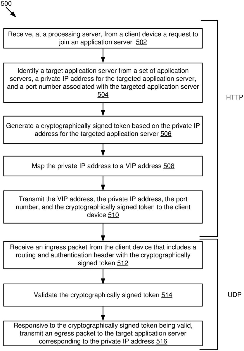
FIG.5is an example flow diagram written from the processing server111perspective, according to some embodiments described therein. The method illustrated in flowchart500may be performed by the computing device200inFIG.2.
The method500may begin at block502. At block502, a processing server111receives from a client device a request to join an application server115. Block502may be followed by block504.
At block504, a target application server115ais identified from a set of application servers115, a private IP address for the targeted application server115, and a port number associated with the targeted application server115. Block504may be followed by block506.
At block506, a token is generated based on the private IP address for the targeted application server115. Block506may be followed by block508.
At block508, the private IP address is mapped to a VIP address. Block508may be followed by block510.
At block510, the VIP address, the private IP address, the port number, and the token are transmitted to the client device101. In some embodiments, blocks502-510are performed over HTTP at the application server111. Block510may be followed by512.
At block512, an ingress packet is received from the client device that includes a routing and authentication header with the token, Block512may be followed by block514.
At block514, the token is validated. Block514may be followed by block516.
At block516, responsive to the token being valid, an egress packet is transmitted to the target application server115acorresponding to the private IP address. In some embodiments, blocks512-516are performed over UDP at the demultiplexer150.
The methods, blocks, and/or operations described herein can be performed in a different order than shown or described, and/or performed simultaneously (partially or completely) with other blocks or operations, where appropriate. Some blocks or operations can be performed for one portion of data and later performed again, e.g., for another portion of data. Not all of the described blocks and operations need be performed in various implementations. In some implementations, blocks and operations can be performed multiple times, in a different order, and/or at different times in the methods.
In the above description, for purposes of explanation, numerous specific details are set forth in order to provide a thorough understanding of the specification. It will be apparent, however, to one skilled in the art that the disclosure can be practiced without these specific details. In some instances, structures and devices are shown in block diagram form in order to avoid obscuring the description. For example, the embodiments can be described above primarily with reference to user interfaces and particular hardware. However, the embodiments can apply to any type of computing device that can receive data and commands, and any peripheral devices providing services.
Reference in the specification to “some embodiments” or “some instances” means that a particular feature, structure, or characteristic described in connection with the embodiments or instances can be included in at least one implementation of the description. The appearances of the phrase “in some embodiments” in various places in the specification are not necessarily all referring to the same embodiments.
Some portions of the detailed descriptions above are presented in terms of algorithms and symbolic representations of operations on data bits within a computer memory. These algorithmic descriptions and representations are the means used by those skilled in the data processing arts to most effectively convey the substance of their work to others skilled in the art. An algorithm is here, and generally, conceived to be a self-consistent sequence of steps leading to a desired result. The steps are those requiring physical manipulations of physical quantities. Usually, though not necessarily, these quantities take the form of electrical or magnetic data capable of being stored, transferred, combined, compared, and otherwise manipulated. It has proven convenient at times, principally for reasons of common usage, to refer to these data as bits, values, elements, symbols, characters, terms, numbers, or the like.
It should be borne in mind, however, that all of these and similar terms are to be associated with the appropriate physical quantities and are merely convenient labels applied to these quantities. Unless specifically stated otherwise as apparent from the following discussion, it is appreciated that throughout the description, discussions utilizing terms including “processing” or “computing” or “calculating” or “determining” or “displaying” or the like, refer to the action and processes of a computer system, or similar electronic computing device, that manipulates and transforms data represented as physical (electronic) quantities within the computer system's registers and memories into other data similarly represented as physical quantities within the computer system memories or registers or other such information storage, transmission, or display devices.
The embodiments of the specification can also relate to a processor for performing one or more steps of the methods described above. The processor may be a special-purpose processor selectively activated or reconfigured by a computer program stored in the computer. Such a computer program may be stored in a non-transitory computer-readable storage medium, including, but not limited to, any type of disk including optical disks, ROMs, CD-ROMs, magnetic disks, RAMS, EPROMs, EEPROMs, magnetic or optical cards, flash memories including USB keys with non-volatile memory, or any type of media suitable for storing electronic instructions, each coupled to a computer system bus.
The specification can take the form of some entirely hardware embodiments, some entirely software embodiments or some embodiments containing both hardware and software elements. In some embodiments, the specification is implemented in software, which includes, but is not limited to, firmware, resident software, microcode, etc.
Furthermore, the description can take the form of a computer program product accessible from a computer-usable or computer-readable medium providing program code for use by or in connection with a computer or any instruction execution system. For the purposes of this description, a computer-usable or computer-readable medium can be any apparatus that can contain, store, communicate, propagate, or transport the program for use by or in connection with the instruction execution system, apparatus, or device.
A data processing system suitable for storing or executing program code will include at least one processor coupled directly or indirectly to memory elements through a system bus. The memory elements can include local memory employed during actual execution of the program code, bulk storage, and cache memories which provide temporary storage of at least some program code in order to reduce the number of times code must be retrieved from bulk storage during execution.
Claims
- A computer-implemented method performed at a processing server, the method comprising: receiving a request to join an application server from a client device;identifying a targeted application server from a set of application servers, a private internet protocol (IP) address for the targeted application server, and a port number associated with the targeted application server;generating a token based at least in part on the private IP address for the targeted application server;mapping the private IP address to a virtual IP (VIP) address;and transmitting, the VIP address, the private IP address, the port number, and the token to the client device.
- The method of claim 1, wherein the token is a hash of a client device IP address of the client device, the private IP address, and a secret key, and wherein the secret key is stored at the processing server.
- The method of claim 2, wherein the secret key is selected from a set of secret keys that are updated periodically.
- The method of claim 1, further comprising: receiving, from the client device, an ingress packet at a demultiplexer that corresponds to the VIP address, wherein the ingress packet includes a routing and authentication header;parsing the routing and authentication header to obtain the private IP address, the port number, and the token;determining, using a secret key, whether the token is valid;and responsive to determining that the token is valid, forwarding the ingress packet to the targeted application server.
- The method of claim 4, wherein: the processing server is one of a plurality of processing servers mapped to the VIP address;the ingress packet is received by a first processing server that is different from a second processing server that received the request to join;and the first processing server determines that the token is valid using information from the ingress packet and the secret key.
- The method of claim 4, wherein determining whether the token is valid includes comparing the token to a hash of a client device IP address, the private IP address, and the secret key to confirm that both values are equal.
- The method of claim 4, wherein forwarding the ingress packet to the targeted application server includes using a tunnel to forward the ingress packet by generating an encapsulated packet.
- The method of claim 4, further comprising: responsive to determining that the token is invalid, performing one or more of dropping future ingress packets from the client device or automatically blocking the client device IP address.
- The method of claim 4, wherein receiving the request to join and transmitting the token are over hypertext transfer protocol (HTTP) and wherein receiving the ingress packet at the VIP address occurs over user datagram protocol (UDP).
- The method of claim 4, wherein the demultiplexer steers the ingress packet to a specific Point of Presence (PoP) that hosts the targeted application server.
- The method of claim 1, wherein the token is a first token and further comprising: generating a second token using a second secret key, wherein generating the second token is performed after at least a predetermined amount of time has passed from generating the token;wherein generating the second token invalidates the first token.
- The method of claim 1, wherein: the processing server is one of a plurality of processing servers mapped to the VIP address;incoming packets are sharded among the plurality of processing servers;and each of the plurality of processing servers receives a secret key that is used for authentication of the token.
- The method of claim 1, wherein identifying the targeted application server from the set of application servers is based on a client device IP address of the client device and selecting the targeted application server that is closest to a location of the client device as compared to other application servers in the set of application servers.
- The method of claim 1, wherein: the token is a hash of a client device IP address of the client device, the private IP address, and a secret key;and the processing server receives a randomly selected value and generates the secret key from the randomly selected value.
- A device comprising: a processor;and a memory coupled to the processor, with instructions stored thereon that, when executed by the processor, cause the processor to perform operations comprising: receiving a request to join an application server from a client device;identifying a targeted application server from a set of application servers, a private internet protocol (IP) address for the targeted application server, and a port number associated with the targeted application server;generating a token based at least in part on the private IP address for the targeted application server;mapping the private IP address to a virtual IP (VIP) address;and transmitting, the VIP address, the private IP address, the port number, and the token to the client device.
- A non-transitory computer-readable medium with instructions stored thereon that, when executed by one or more computers, cause the one or more computers to perform operations, the operations comprising: receiving a request to join an application server from a client device;identifying a targeted application server from a set of application servers, a private internet protocol (IP) address for the targeted application server, and a port number associated with the targeted application server;generating a token based at least in part on the private IP address for the targeted application server;mapping the private IP address to a virtual IP (VIP) address;and transmitting, the VIP address, the private IP address, the port number, and the token to the client device.
- The computer-readable medium of claim 16, wherein the token is a hash of a client device IP address of the client device, the private IP address, and a secret key, and wherein the secret key is stored at a processing server.
- The computer-readable medium of claim 17, wherein the secret key is selected from a set of secret keys that are updated periodically.
- The computer-readable medium of claim 16, wherein the operations further comprise: receiving, from the client device, an ingress packet at a demultiplexer that corresponds to the VIP address, wherein the ingress packet includes a routing and authentication header;parsing the routing and authentication header to obtain the private IP address, the port number, and the token;determining, using a secret key, whether the token is valid;and responsive to determining that the token is valid, forwarding the ingress packet to the targeted application server.
- The computer-readable medium of claim 19, wherein: the processing server is one of a plurality of processing servers mapped to the VIP address;the ingress packet is received by a first processing server that is different from a second processing server that received the request to join;and the first processing server determines that the token is valid using information from the ingress packet and the secret key.
Disclaimer: Data collected from the USPTO and may be malformed, incomplete, and/or otherwise inaccurate.