U.S. Pat. No. 11,998,834
Systems and Methods for Establishing Direct Communication Between a Server System and a Video Game Controller
AssigneeSony Interactive Entertainment LLC
Issue DateJune 15, 2021
Illustrative Figure
Abstract
Systems and methods for establishing direct communication between a server system and a video game controller are described. The systems and methods include the video game controller and a computing device. An application is executed by the server system when a session is established by the computing device with the server system. Once the application is executed, the video game controller is used to send an identifier to the server system. The server system verifies the identifier to pair the session with the video game controller. When the video game controller is paired with the session, the video game controller can be used to change a state of a virtual scene that is displayed on the computing device or on a display screen.
Description
DETAILED DESCRIPTION Systems and methods for establishing direct communication between a server system and a video game controller are described herein. It should be noted that various embodiments described in the present disclosure may be practiced without some or all of these specific details. In other instances, well known process operations have not been described in detail in order not to unnecessarily obscure various embodiments described in the present disclosure. FIG.1Ais a diagram of an embodiment of a system100to illustrate pairing of a controller102with a session106. Examples of the controller102include a hand-held controller, which can be a Sony™ DualShock™ controller, a gun-shaped controller, a PlayStation™ Move™ controller, a stick-shaped controller, a cellular phone, a mobile device, a tablet, a video game controller, a joystick, a glove-shaped controller, or a steering wheel-shaped controller, etc. Examples of the session106include a game session, a video session, a virtual image session, an augmented reality image session, a virtual reality image session, etc. As an illustration, the session106is an instance of execution of an application1, which can be a game execution application that allows a play of a game application or a video conferencing application that allows images of a real-world environment to be transferred via the computer network122between two clients. Examples of the real-world environment include a room or a confined location or an enclosed environment or an environment that is enclosed by walls or a cubicle. The session106starts when a user A logs into a user account1and ends when the user A logs out of the user account1. For example, an instance of execution of the session106starts when the user A logs into his/her user account1and ends for the user account1when the user A logs out of the user account1. The logging out by the user A disables game play by the user ...
DETAILED DESCRIPTION
Systems and methods for establishing direct communication between a server system and a video game controller are described herein.
It should be noted that various embodiments described in the present disclosure may be practiced without some or all of these specific details. In other instances, well known process operations have not been described in detail in order not to unnecessarily obscure various embodiments described in the present disclosure.
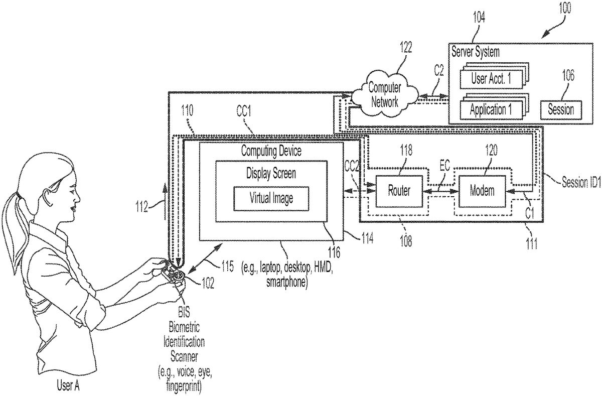
FIG.1Ais a diagram of an embodiment of a system100to illustrate pairing of a controller102with a session106. Examples of the controller102include a hand-held controller, which can be a Sony™ DualShock™ controller, a gun-shaped controller, a PlayStation™ Move™ controller, a stick-shaped controller, a cellular phone, a mobile device, a tablet, a video game controller, a joystick, a glove-shaped controller, or a steering wheel-shaped controller, etc. Examples of the session106include a game session, a video session, a virtual image session, an augmented reality image session, a virtual reality image session, etc. As an illustration, the session106is an instance of execution of an application1, which can be a game execution application that allows a play of a game application or a video conferencing application that allows images of a real-world environment to be transferred via the computer network122between two clients. Examples of the real-world environment include a room or a confined location or an enclosed environment or an environment that is enclosed by walls or a cubicle. The session106starts when a user A logs into a user account1and ends when the user A logs out of the user account1. For example, an instance of execution of the session106starts when the user A logs into his/her user account1and ends for the user account1when the user A logs out of the user account1. The logging out by the user A disables game play by the user A and the logging in by the user A into the user account1is performed to enable the game play. The user A logs out of the user account1by selecting a button on the controller102or another controller, described herein.
The system100includes the controller102, a computing device114, a computer network122, a server system104, a router118, and a modem120. As an example, the router118and the modem120are locally situated with respect to the controller102. For example, the router118and the modem120are situated in the same real-world environment in which the controller102is situated.
The computing device114is a machine for performing calculations. Examples of the computing device114include a smart television, a tablet, a smart phone, a head-mounted display (HMD), an electronic computer, an information processing system, a desktop computer, and a laptop computer. Another example of the computing device114includes a combination of a display device and a game console. The display device is coupled to the game console. The computer network122is a group of computing hardware devices that are linked together through communication channels to facilitate communication and resource sharing among users. The computer network122can be a wide area network or a local area network or a combination of the wide area network and the local area network. Internet is an example of the wide area network and Intranet is an example of the local area network.
The server system104includes a single or multiple servers that execute the application1and other applications. For example, each server includes a server operating system (OS) that is designed to run on the server. Each server is a specialized computer that serves requests from a client, such as a computing device or a controller or a display device, described herein. The specialized computer includes a processor and a memory device. The processor is coupled to the memory device. As used herein, terms, such as a processor, an application specific integrated circuit (ASIC), a programmable logic device (PLD), and a central processing unit (CPU), a server, a microprocessor, are used herein interchangeably. Examples of a memory device include a read-only memory and a random access memory. To illustrate, the memory device is a flash memory, a hard disk drive, or a redundant array of independent disks (RAID).
The modem120is a device that performs modulation and demodulation of data to allow the client to connect to the computer network122. As an example, the modem120applies a network communication protocol, such as Transmission Control Protocol (TCP/IP) to extract data from transfer packets. The modem120applies the network communication protocol to embed data into transfer packets. An example of the modem120is a broadband modem that allows the client to access the Internet via a cable or a digital subscriber line (DSL). The modem120routes a data signal received from the router118to the server system104via the computer network122. In addition, the modem120routes a data signal received from the server system104via the computer network122to the router118. The modem120is coupled at one end to a cable or the DSL, which is coupled to the computer network122. In one embodiment, the terms data and information are used herein interchangeably.
The router118directs a data signal that is received from the server system104via the computer network112to the computing device114or the controller102based on a destination address received by the router118with the data signal. For example, the router118determines that the data signal has a destination address of the computing device114and directs the data signal to the computing device114assigned the destination address. An example of a destination address is an Internet Protocol (IP) address or a media access layer (MAC) address or a combination thereof. The destination address of the computing device114is different from the destination address of the controller102. For example, at least one alphanumeric character of the destination address of the controller102is different from at least one alphanumeric character of the destination address of the computing device114. The router118determines that another data signal has a destination address of the controller102and directs the other data signal to the controller102. An example of the router118is a broadband router. The computing device114has a display screen116, such as a liquid crystal display (LCD) screen, a light emitting diode (LED) display screen, or a plasma display screen, which is a display part of a monitor or a display device.
The server system104stores multiple user accounts1through N. Each user account is assigned to a user. For example, the user account1is assigned to the user A and another user account2is assigned to another user B.
The controller102is coupled to the router118via a connection channel CC1. An example of the connection channel CC1is a wireless connection, such as a wireless local area network (LAN) or a Wi-Fi connection or a Bluetooth™ connection. Wi-Fi is a wireless networking technology that uses radio waves or electromagnetic waves to provide a wireless high-speed connection to the computer network122. Similarly, the computing device114is connected to the router118via a connection channel CC2, which is also a wireless connection. The connection channel CC1or CC2can be a radio frequency and has a specific data rate, measured in bits per second, and a bandwidth, measured in hertz. An example of each of the connection channel CC1and CC2is a wireless connection channel that applies a wireless communication protocol, such as Wi-Fi™ or Bluetooth™. The connection channel CC2of the computing device114with the router118is different from the connection channel CC1of the controller102with the router118. For example, the wireless connection of the computing device114with the router118has a different data transfer rate between the computing device114and the router118compared to a data transfer rate between the controller102and the router118.
The router118is coupled to the modem120via an Ethernet cable EC. The modem120is coupled to the computer network122via a connection C1and the server system104is coupled to the computer network122via another connection C2. The connection C1includes a group of cables or digital subscriber lines and the connection C2includes a gateway device and a group of cables or digital subscriber lines. A combination of the connection channel CC1, the router118, the cable EC, the modem120, and the connection C1is sometimes referred to herein as a connection channel111.
The user A powers on the computing device114and accesses the user account1. For example, the user A accesses a login website from the server system104via the computer network122. The user A uses an input device, such as a keyboard or a pad or a mouse, of the computing device114to provide his/her login information, which can include a username and a password, assigned to the user A. The login information is sent from the computing device114via the connection channel CC2to the router118. The router118sends the login information to the modem120via the cable EC. The modem120generates one or more transfer packets embedding the login information and sends the transfer packets via the connection C1, the computer network122, and the connection C2to the server system104.
A server of the server system104determines that the login information is authentic and provides access to the user account1and establishes the session106. To establish the session106, the server system104executes an instance of the application1and sends one or more transfer packets that include information associated with the session106to the computing device11via the connection C2, the computer network122, the connection C1, the modem120, the cable EC, the router118, and the connection channel CC2. An example of the information associated with the session106includes information identifying the application1, such as a name of the application1that is allowed access upon providing access to the user account1, a title of the application1, or virtual image data that identifies the application1, or audio data that identifies the application1, or a combination of two or more thereof. To illustrate, the information associated with the session106has image data for displaying an introductory image of a video game at the computing device114and audio data that is synchronized to the display of the introductory image. As another illustration, the information associated with the session105includes a uniform resource locator (URL) of a gaming website accessed to view features of and to play the video game. Another example of the information associated with the session105includes a notice that the user A provides his/her biometric information via the controller102by using a biometric information scanner BIS of the controller102. To illustrate, the information associated with the session106includes the notice that the user A press his/her finger against a fingerprint reader on the controller102or that the user A speak into a microphone of the controller102or that the user A scan his/her eye into a biometric eye scanner of the controller102. Examples of a biometric information scanner include the fingerprint reader, the microphone, and the biometric eye scanner. Another example of the information associated with the session105includes the information identifying the application1and the notice that the user A provides his/her biometric information via the controller102. The biometric information is unique to the user A and distinguishes the user A from other users. Yet another example of the information associated with the session106includes the information identifying the application1and an instruction to be sent to the controller102to provide its device identification (ID). Examples of the device ID include a serial number of the controller102, a MAC address of the controller102, and a combination thereof. The device ID of the controller102is unique to the controller102and distinguishes the controller102from other controllers, which can be the same in structure and function as the controller102. Still another example of the information associated with the session106includes the information identifying the application1and an instruction to be sent to the controller106to provide a network identification (ID). Examples of the network ID include a network address of the router118. The network ID stored within the controller102is unique to the router118and distinguishes the router118from other routers.
One or more transfer packets having the information associated with the session106and sent from the server system104also include a destination address of the router118and one or more additional destination addresses, such as the destination address of the computing device114and the destination address of the controller102. Upon receiving the transfer packets including the information associated with the session106, the modem120applies the network communication protocol to depacketize the transfer packets to identify the destination address of the router118, the destination address of the computing device114, the destination address of the controller102, and the information associated with the session106. It should be noted that the destination address of the controller102is pre-stored in a memory device of the server system104. For example, when the user A makes an in-person purchase of the controller102, the user A provides his/her user account information to an entity that sells the controller102to the user A. The entity makes a selection via an input device of a client device to register the controller102with the user account1. Upon receiving a signal generated based on the selection from the client device, one or more processors, described herein, of the server system104register a device ID of the controller102with the user account1to register the controller102with the user account1. To illustrate, the one or more processors of the server system104stores a link between the user account1and a device ID of the controller102within a mapping database, described below. As another example, when the user A makes an online purchase of the controller102, the user A provides his/her user account information to a website, such as a retailer website or a manufacturer website, accessed by the user A for the purchase. The user account information is sent from the website to the server system104for the one or more processors to register the controller102with the user account1. Examples of the user account information include an email address used by accessing the user account1of the user A, a user name assigned to the user account1, a residence address associated with the user account1, or a phone number associated with the user account1, or a combination thereof. The modem120sends the destination address of the computing device114, the destination address of the controller102, and the information associated with the session106via the cable EC to the router118.
Upon receiving the destination address of the computing device114and the information associated with the session106, the router118determines that the information associated with the session106is to be sent to computing device114and sends the information associated with the session106to the computing device114via the connection channel CC2. A combination of the connection channel CC2, the router118, the cable EC, the modem120, the connection C1, the computer network122, the connection C2is referred to herein as a communication channel108, which is illustrated using long and short dashed lines “”.
Similarly, upon receiving the destination address of the controller102and the information associated with the session106, the router118determines that the information associated with the session106is to be sent to controller102and sends the information associated with the session106to the controller102via the connection channel CC1. A combination of the connection channel CC1, the router118, the cable EC, the modem120, the connection C1, the computer network122, the connection C2is referred to herein as a communication channel110, which is illustrated using “o”s.
Upon receiving the information associated with the session106, the computing device114displays the information on the display screen116or outputs the audio data within the information associated with the session106via one or more speakers of the computing device114or both displays the information and outputs the audio data. Upon reading the information associated with the session106displayed on the display screen116or listening to the audio data, the user A provides his/her biometric ID, such as voice or fingerprint, or retinal information, to the biometric information scanner BIS. For example, the user A says “Hey Controller” to provide his/her voice to the biometric information scanner BIS.
In case the information associated with the session106includes the instruction for the controller102to provide its device ID, the controller102accesses the device ID from a memory device of the controller102. Also, in case the information associated with the session106includes the instruction for the controller102to provide the network ID, the controller102accesses the network ID from a memory device of the controller102. The biometric ID or the device ID or the network ID a combination of two or more thereof is referred to herein as identification information.
The identification information and an instruction to provide the identification information to a destination address of the server system104is sent from the controller102via the communication channel CC1to the router118. As an example, the URL of the gaming website is stored in firmware of a read-only memory or in another memory device of the controller102. The URL includes the destination address of the server system104. As another example, the computing device114provides the URL of the server system104via a wireless connection115to the controller102. The computing device114or another device, such as the game console, is bypassed or not used in sending the identification information. For example, the identification information is not sent from the controller102to the computing device114or the game console. As another example, the identification information is not addressed by the controller102to be sent to the computing device114or to the game console. The identification information is addressed by the controller102to be sent to the server system104. The computing device114is coupled to the controller102via a wireless connection115, such as a Bluetooth™ connection or a Bluetooth™ connection or another short-range connection.
The router118receives the identification information and the instruction via the communication channel CC1, identifies the destination address of the server system104within the instruction, and routes the identification information to the modem120via the cable EC. The modem120receives the identification information and the instruction, identifies the destination address of the server system104within the instruction, applies the network communication protocol to the identification information to generate transfer packets and sends the transfer packets via the connection C1, the computer network122, and the connection C2to the server system104. The server system104receives the identification information and pairs the controller102with the session106upon verifying that the identification information.
The server system104generates and sends a pairing notification in response to pairing the controller102with the session106. For example, the pairing notification includes image frames to be displayed on the computing device114, or audio frames to be output as sound by the computing device114, or a combination thereof. The image frames include information for displaying the pairing notification, such as color and intensity and texture of the pairing notification. As another example, the pairing notification includes an instruction to a rendering program that is executed by a graphical processing unit (GPU) of the computing device114, or an instruction to an audio processor of the computing device114for processing audio data, or both the instructions. The server system104sends the pairing notification via the connection C2, the computer network122, the connection C1, the modem120, the cable EC, the router108, and the connection channel CC2to the computing device114. The modem120receives one or more transfer packets including the pairing information and a destination address of the computing device114from the server system104via the connection C2, the computer network122, and the connection C1. The modem120applies the network communication protocol to the transfer packets to extract the destination address of the computing device114and the pairing notification, and sends the pairing notification and the destination address to the router118via the cable EC. The router118determines from the destination address of the computing device114that the pairing notification is to be sent to the computing device114, and sends the pairing notification to the computing device114via the connection channel CC2. For example, the router118identifies from an IP address of the computing device114that the pairing notification is to be sent to the computing device114. Upon receiving the pairing notification that includes the image frames or audio frames or a combination thereof, the pairing information is output as one or more images on the display screen116of the computing device114or as sound via one or more speakers of the computing device114or a combination thereof. Upon receiving the pairing information that includes the instruction to the rendering program. the GPU of the computing device114executes the rendering program to display the pairing notification on the display screen116. Also, when the pairing notification includes the instruction to the audio processor, the audio processor and one or more speakers of the computing device114execute the instruction to process the audio data to output the audio data as sound. Similarly, when the pairing notification includes both the instructions, both the GPU and the audio processor synchronize with each other to output the pairing notification as images and sound.
Once the session106is paired, such as linked or associated with, with the controller102, the controller102can be used by the user A to interact with the session106to establish a direct communication between the server system104and the controller102. For example, the controller102can be used by the user A to play the game generated by executing the application1. To illustrate, the controller102can be used by the user A to provide input data, such as controller movement data, controller button presses, etc., to the server system104via the communication channel110to change a state of a virtual scene being displayed on the computing device114.
Before the session106is paired with the controller102, the controller102cannot be used by the user102to interact with the session106of execution of the application1to change the state of the virtual scene displayed on the computing device114. For example, the user A selects or moves an input device of the controller102. The selection or movement of the input device generates input information, which is not processed by or disallowed the server system102to change the state of the virtual scene. The input information transferred from the controller102to the server system102via the communication channel110for changing the state of the virtual scene generated by execution of the application1is not processed by the server system104for changing the state of the virtual scene until the controller102is paired with the session106.
In one embodiment, in a multi-player game, such as a multi-player race car game or a soccer game, the logging out by the user A from the user account1does not affect other instances of execution of the session106for other users also playing the game. The instances of the session106for the other users continue until they log out of their corresponding user accounts.
In an embodiment, the user A physically transfers the controller102or another controller, described herein, to another user. If the other user uses the user account1assigned to the user A, the instance of the session106associated with the user account1continues. However, if the other user users his/her user account2after logging out of the user account1, another instance of the session106initiates for the user account2.
In one embodiment, the session106ends when the computing device114on which the virtual scene is being displayed is disconnected from the server system104or when the computing device114is powered off, or a communication signal between the computing device114and the server system104is weak, e.g., has an amount of power that is less than a threshold, or a communication device of the computer network122is not functional or is malfunctioning, or a communication device of the computing device114is not functional or is malfunctioning.
In an embodiment, both the router118and the modem120are integrated into a single hardware device.
In one embodiment, the connection channel CC2is a wired connection channel, such as a coax cable. Similarly, the connection channel CC1is a wired connection.
In an embodiment, functions described herein as being performed by the server system104are performed by one or more processors of the server system104. Similarly, in an embodiment, functions described herein as being performed by the modem120are performed by one or more processors of the modem120. Also, in an embodiment, functions described herein as being performed by the router118are performed by one or more processors of the router118. In one embodiment, functions described herein as being performed by the controller102are performed by one or more processors of the controller102.
In an embodiment, a pairing notification, described herein, is not sent from the server system104to the computing device114.
In one embodiment, the computing device114is not coupled to the controller102via the wireless connection115.
In one embodiment, the controller102sends a request to the computing device114to obtain the destination address of the server system104before sending the identification information to the server system104. For example, The computing device114requests that the wireless connection115occur between the computing device114and the controller102. Once the wireless connection115is established, the controller102sends a request to the server system104via the wireless connection115for obtaining the destination address. Upon receiving the request, the computing device114provides the destination address of the server system104to the controller102via the wireless connection115.
In an embodiment, the session106does not end when another user uses the controller102. The other user receives the controller102from the user A while the session106is active after being initiated. The other user provides his/her login information to the server system104via the computing device114to log into his/her user account to initiate another instance of the session106for the user account of the other user. The session106remains active and does not end when the other user switches to his/her account from the user account1.
FIG.1Bis a diagram of an embodiment of the controller102to illustrate wireless communication of the controller102with the router118. The controller102includes a motion sensor system152, a wireless communication integrated circuit (IC)156, an input device150, a computer network ID chip151, a wireless communication IC157, the biometric identification sensor BIS, a processor194, and a device ID chip158. The processor194is coupled to the motion sensor system152, wireless communication integrated circuit (IC)156, the input device150, the computer network ID chip151, the wireless communication IC157, the biometric identification sensor BIS, and the device ID chip158. The input device150is coupled to the motion sensor system152. Examples of the motion sensor system152include one or more gyroscopes, one or more accelerometers, and one or more magnetometers to facilitate a determination of a position and orientation of the controller102and to facilitate a determination of changes to the position and orientation. Examples of the input device150include a button, a switch, a touch screen, a stylus, a joystick, a microphone, a gun trigger, etc. Examples of the wireless communication IC157include a Bluetooth™ device or a Wi-Fi™ device that enables communication between the controller102and the computing device114(FIG.1A) via the wireless connection115(FIG.1A). To illustrate, a Bluetooth™ device includes a processor that facilitates a transfer of data over short distances using short-wavelength ultra high frequency (UHF) radio waves in an industrial, scientific, and medical (ISM) band from 2.4 to 2.485 GHz between a controller and another device, such as a computing device, building personal area networks (PANs).
The device ID chip158is a memory chip that stores the device ID, such as a MAC address or a unique identification number, of the controller102. For example, the device ID chip158stores a sequence of alphanumeric characters, which are unique to the controller102and distinguishes the controller102from other controllers. An example of the wireless communication IC156includes a Wi-Fi™ device that allows Wi-Fi™ communication between the controller102and the router118via the connection channel CC1(FIG.1A). To illustrate, the wireless communication IC156is a network interface card (NIC) that couples a controller, as described herein, via the connection channel CC1and the router118to the computer network122.
The computer network ID chip151is another memory chip that stores the network ID, such as an Internet Protocol (IP) address, of the router118ofFIG.1A. The router118is identified within the computer network122using the network ID stored in the computer network ID chip151. For example, the computer network ID chip151stores a sequence of alphanumeric characters, which are unique to the router118and distinguishes the router118from other routers within the computer network122.
The device ID of the controller102and the other corresponding device IDs of the other controllers are pre-registered with the server system104before the session106(FIG.1A) starts. For example, the device ID unique to the controller102is hardwired into the controller102and the server system104stores the device ID. The device ID of the controller102and additional device IDs of the other controllers are stored in a device ID database of the server system104. The device ID database is stored in one or more memory devices of the server system104.
Also, the network ID identifying the router118is pre-registered with the server system104before the controller102sends the identification information to the server system104to pair the controller102with the session106. For example, during establishment of the session106, the server system104sends an instruction to the computing device114via the communication channel108to provide the network ID. Upon receiving the instruction, the computing device114accesses the network ID stored in a memory device of the computing device114, and sends the network ID via the communication channel108(FIG.1A) to the server system104. The server system104receives the network ID and stores the network ID in a network ID database of the server system104. The network ID database is stored in one or more memory devices of the server system104. Also, the server system104associates, such as establishes a one-to-one correspondence or a link, between the network ID and the user account1after the session106is established.
Moreover, the biometric ID identifying the user A is pre-registered with the server system104before the controller102sends the identification information to the server system104to pair the controller102with the session106. For example, the computing device114has a biometric information scanner. After the session106is established or while the session106is being established, the server system104sends an instruction to the computing device114via the communication channel108to request the biometric ID from the user A. When the computing device114receives the instruction, the computing device114displays a message or output a sound to request the biometric ID from the user A. Upon receiving the biometric ID via the biometric information scanner of the computing device114from the user A, the computing device114sends the biometric ID via the communication channel108to the server system104. The server system104receives the biometric ID and stores the biometric ID in a biometric ID database of the server system104. The biometric ID database is stored in one or more memory devices of the server system104. Also, the server system104associates, such as establishes a one-to-one correspondence or a link, between the biometric ID and the user account1.
After the session106is established between the computing device114and the server system104, the user A provides his/her biometric ID to the biometric identification scanner BIS of the controller102to pair the controller102with the session106. For example, after the session106starts, upon viewing the notice that the user A press his/her finger against a fingerprint reader on the controller102or that the user A speak into the microphone of the controller102or that the user102scan his/her eye into the biometric eye scanner of the controller102, the user A provides his/her biometric information to the biometric information scanner BIS of the controller102. Upon receiving the biometric ID, the biometric identification scanner BIS of the controller102generates a biometric identification signal and sends the biometric identification signal to the processor194. The processor194receives the biometric identification signal and generates an instruction to send the biometric identification signal to the server system104. For example, the instruction includes a destination address of the server system104. The processor194sends the instruction and the biometric identification signal to the wireless communication IC156. The wireless communication IC156applies the wireless communication protocol to the biometric identification signal and the instruction and sends the biometric identification signal and the instruction via the connection channel CC1(FIG.1A) to the router118. The router118determines from the destination address within the instruction that the biometric identification signal is to be sent to the server system104and sends the instruction and the biometric identification signal to the modem120. The modem120applies the network communication protocol to the biometric identification signal to generate one or more transfer packets and sends the transfer packets via the connection C1, the computer network122, and the connection C2to the server system104. The transfer packets having the biometric identification signal is an example of a connection request.
As an alternative or in addition to sending the biometric identification signal after the session106is established between the computing device114and the server system104, the processor194accesses the device ID from the device ID chip158and generates an instruction to send the device ID to the server system104to pair the controller102with the session102. The processor194sends the instruction and the device ID to the wireless communication IC156. The wireless communication IC156applies the wireless communication protocol to the device ID and the instruction and sends the device ID and the instruction via the connection channel CC1(FIG.1A) to the router118. The router118determines from the instruction that the device ID is to be sent to the server system104and sends the instruction and the device ID to the modem120. The modem120generates one or more transfer packets having the device ID and sends the transfer packets via the connection C1, the computer network122, and the connection C2to the server system104. The transfer packets having the device ID is another example of the connection request.
Also, as an alternative or in addition to sending the biometric identification signal after the session106starts, or as an alternative or in addition to sending the device ID after the session106starts, the processor194accesses the network ID from the computer network ID chip151and generates an instruction to send the network ID to the server system104to pair the controller102with the session106. The processor194sends the instruction and the network ID to the wireless communication IC156. The wireless communication IC156applies the wireless communication protocol to the network ID and the instruction and sends the network ID and the instruction via the connection channel CC1to the router118. The router118determines from the instruction that the network ID is to be sent to the server system104and sends the instruction and the network ID to the modem120. The modem120generates one or more transfer packets from the network ID and sends the transfer packets via the connection C1, the computer network122, and the connection C2to the server system104. The transfer packets having the network ID is yet another example of the connection request.
It should be noted that the connection request is not sent via the game console or the computing device114. There is no use of the game console or the computing device114in transferring the connection request from the controller102to the server system104.
Once the device ID, or the biometric ID, or the network ID, or a combination of two or more thereof is used by the server system104to pair the controller102with the session106, the controller102can be used by the user A to generate and provide inputs for changing the state of the virtual scene that is displayed upon execution of application1. For example, once the controller102is paired with the server system104, the user A can use the controller102to change the state of the virtual scene. The user A uses the controller102by selecting or moving the input device150or moving the controller102to provide a selection. The input device150generates an input signal upon receiving the selection or movement of the input device150and/or the motion sensor system152generates an input signal when the controller102moves. The input signal generated by the motion sensor152includes data for determining the position or orientation of the controller102and/or data for determining a position and an orientation of the input device150. Examples of the data for calculating the position or orientation of the controller102includes an acceleration of the controller102, an angular velocity of the controller102, and an orientation of the controller102. The position and orientation of the controller102and the position and orientation of the input device150are measured with reference to a reference co-ordinate system within the controller102. Examples of the data for calculating the position and orientation of the input device150include an acceleration of the input device150, an angular velocity of the input device150, and an orientation of the input device150. The processor194receives one or more of the input signals.
The processor194receives the one or more input signals to output input information. As an example, the input information includes the data for calculating the position or orientation or a combination thereof of the controller102or includes the data for calculating the position or orientation or a combination thereof of the input device150or the selection made by the user A via the input device150. To illustrate, the input information includes which of a plurality of buttons of the input device150are selected by the user A or which of a plurality of joysticks of the input device150are moved and in which direction. In addition to the input information, the processor194also generates an instruction to send the input information to a destination address of the server system104.
The processor194sends the input information via the communication channel110to the server system104. For example, the processor194sends the input information and the instruction to the wireless communication IC156. The wireless communication IC156applies the wireless communication protocol to the input information and the instruction and sends the input information and the instruction via the connection channel CC1(FIG.1A) to the router118. The router118determines from the instruction that the input information is to be sent to the server system104and sends the instruction and the input information to the modem120. The modem120generates one or more transfer packets from the input information and sends the transfer packets via the connection C1, the computer network122, and the connection C2to the server system104.
In one embodiment, the wireless communication IC156and the wireless communication IC157are integrated into a single integrated circuit chip. In an embodiment, the wireless communication IC156is integrated into one integrated circuit chip and the wireless communication IC157is integrated into another integrated circuit chip.
FIG.1Cis a diagram of an embodiment of a system159to illustrate use of a communication channel155, which includes a cellular connection channel151and a cellular connection channel153. The communication channel155is illustrated as small dashes “ - - - ” inFIG.1C. Each of the cellular connection channels151and152is a wireless connection channel, such as a radio frequency connection channel. The communication channel155includes a cellular network154or a mobile network, which includes multiple cell towers, such as a tower TW. Examples of the cellular network154include a mobile broadband network, a fourth-generation (4G) mobile network, a 4G long term evolution (4G LTE), and a fifth-generation (5G) mobile network. The cellular network154transfers data using a cellular communication protocol, such as mobile broadband protocol, the 4G protocol, the 4G LTE protocol, or the 5G protocol. The system159includes a controller160, which is the same in structure and function as the controller102(FIG.1B), except that the controller160couples to the computer network122via the cellular network154instead of via the router118. For example, the destination address of the server system104is stored in firmware of the controller160so that the controller160can send the identification information to the server system104. As another example, the controller160is coupled to the computing device114via the wireless connection115(FIG.1A) to send a request for the destination address of the server system114. Upon receiving the request, the computing device114sends the destination address to the controller160via the wireless connection115.
Each of the cell towers includes a transceiver to transfer data received from the controller160to the computer network122and received from the computer network122to the controller160. A combination of the cellular connection channel151, the multiple towers, the cellular connection channel153, the computer network122, and the connection C2is the communication channel155.
The system159is similar, in structure and function, to the system100ofFIG.1Aexcept that in the system159the controller160is used. The controller160is similar, in structure and function, to the controller102except that the controller160communicates with the server system104via the computer network122and one or more cell towers. Instead of communicating with the computer network122via the connection channel CC1, the router118, the cable EC, the modem120, and the connection C1, the controller160communicates with the computer network122via the cellular connection channel151, the tower TW, and the cellular connection channel152.
When the session106(FIG.1A) of the application1is established or starts, the controller160, such as a subscriber identification module (SIM) card of the controller160, applies the cellular communication protocol to the identification information and an instruction to send the identification information to generate one or more transfer units to transfer to the server system104. The controller160sends the transfer units including the identification information and the instruction via the cellular connection channel151to the tower TW. The computing device114or another device, such as the game console, is bypassed in sending the identification information. For example, the identification information is not sent from the controller160to the computing device114or the game console. As another example, the identification information is not addressed by the controller160to be sent to the computing device114or to the game console. The identification information is addressed by the controller160to be sent to the server system104.
A transceiver of the tower TW receives the transfer units having the identification information and the instruction and the transceiver forwards the transfer units to the computer network122. A gateway, such as a modem, of the computer network122demodulates the transfer units by applying the cellular communication protocol to extract the instruction and the identification information from the transfer units, and applies the network communication protocol to the identification information to generate transfer packets, and sends the transfer packets having the identification information to the server system104via the connection C2. A transfer of the input information from the controller160to the server system102via the communication channel155for changing the state of the virtual scene generated by execution of the application1is disabled or not enabled by the controller160until the controller160is paired with the session106.
FIG.1Dis a diagram of an embodiment of the controller160to illustrate use of a broadband communication IC162to transfer the identification information from the controller160to the server system104(FIG.1C). The controller160includes the input device150, the motion sensor system152, the wireless communication IC157, the biometric identification scanner BIS, the processor194, the broadband communication IC162, and the device ID chip158. An example of the broadband communication IC162is the SIM card. The processor194is coupled to the input device150, the motion sensor system152, the wireless communication IC157, the biometric identification scanner BIS, the broadband communication IC162, and the device ID chip158.
It should be noted that components that are common between the controller102ofFIG.1Aand the controller160operate in the same manner as that described above with respect to the controller102except that the components operate in the manner described above with respect to the controller160instead of the controller102. For example, the motion sensor system152measures data for calculating a position and orientation of the controller160instead of the controller102.
A device ID of the controller160is pre-registered with the server system104before the session106(FIG.1C) starts. For example, the device ID unique to the controller160is hardwired into the controller160and the server system104stores the device ID. The device ID of the controller160is stored in the device ID database of the server system104.
After the session106is established between the computing device114(FIG.1C) and the server system104(FIG.1C), the user A provides his/her biometric ID to the biometric identification scanner BIS of the controller160to pair the controller160with the session106. For example, after the session106starts, upon viewing the notice on the computing device114that the user A press his/her finger against a fingerprint reader on the controller160or that the user A speak into a microphone of the controller160or that the user102scan his/her eye into a biometric eye scanner of the controller160, the user A provides his/her biometric information to the biometric information scanner BIS of the controller160. Upon receiving the biometric ID, the biometric identification scanner BIS of the controller160generates a biometric identification signal and sends the biometric identification signal to the processor194. The processor194receives the biometric identification signal and generates an instruction to send the biometric identification signal to the server system104. For example, the instruction includes a destination address of the server system104. The processor194sends the instruction and the biometric identification signal to the broadband communication IC162. The broadband communication IC162applies the cellular communication protocol to the biometric identification signal and the instruction to generate one or more transfer units, and sends the transfer units via the cellular connection channel151(FIG.1C) to the tower TW, which forwards the transfer units to the computer network122. The computer network122applies the cellular communication protocol to the transfer units to extract the biometric ID and the instruction from the transfer units, further applies the network communication protocol to the biometric ID and the instruction to generate one or more transfer packets, and sends the transfer packets via the connection C2to the server system104.
As an alternative or in addition to sending the biometric identification signal after the session106starts, the processor194of the controller160accesses the device ID of the controller160from the device ID chip158and generates an instruction to send the device ID to the server system104to pair the controller160with the session106. The processor194sends the instruction and the device ID to the broadband communication IC162. The broadband communication IC162applies the cellular communication protocol to the device ID and the instruction to generate one or more transfer units and sends the transfer units via the cellular connection channel151(FIG.1C) to the tower TW, which forwards the transfer units to the computer network122. The computer network122applies the cellular communication protocol to the transfer units to extract the device ID and the instruction from the transfer units, further applies the network communication protocol to the device ID and the instruction to generate one or more transfer packets, and sends the transfer packets via the connection C2to the server system104.
Similarly, when the controller160is paired with the session106to establish a direct communication between the controller160and the server system104, the processor194sends the input information via the communication channel155to the server system104. For example, the processor194sends the input information and an instruction to send the input information to the wireless communication IC156. The wireless communication IC156applies the wireless communication protocol to the input information and the instruction in order to generate one or more transfer units and sends the transfer units having the input information and the instruction via the cellular connection channel151to the tower TW. The tower TW determines from the instruction that the transfer units having the instruction and the input information are to be sent to the server system104and sends the transfer units via other cellular towers to the computer network122. The computer network122applies the cellular communication protocol to the transfer units to extract the input information and the instruction from the transfer units, further applies the network communication protocol to the input information and the instruction to generate multiple transfer packets, and sends the transfer packets via the connection C2to the server system104.
In one embodiment, the broadband communication IC162and the wireless communication IC157are integrated into a single integrated circuit chip. In an embodiment, the broadband communication IC162is integrated into one integrated circuit chip and the wireless communication IC157is integrated into another integrated circuit chip.
In an embodiment, one controller includes both the wireless communication IC156ofFIG.1Band the broadband communication IC162in addition to remaining components illustrated inFIG.1B or1D. In this embodiment, the processor194of the controller determines whether a handover from using the connection channel111(FIG.1A) to using the cellular network154(FIG.1C) or vice versa is to be performed. For example, the processor194determines that the cellular network154has better quality of service (QoS) than the connection channel111or that there is a lower latency in transferring data via the cellular network154compared to the connection channel111. To illustrate, the processor194determines that the cellular network154has a lower amount of data loss or a shorter ping time compared to an amount of loss of data sent via the connection channel111. Upon determining that the cellular network154has better QoS, the processor194determines to use the broadband communication IC162instead of the wireless communication IC156for transferring data, described herein, such as the identification information, from the controller to the server system104. To illustrate, when the user A uses the controller in his/her car, the cellular network154allow for better QoS and lower latency compared to when the user A uses the controller in his/her home. When the user A uses the controller in his/her home, the connection channel111allows for better QoS and lower latency compared to the cellular network154.
It should be noted that in the embodiment, the processor194determines the amount of data loss by sending a pre-determined number of transfer units to provide to the server system104via the communication channel155(FIG.1C) and requesting one or more processors, described herein, of the server system104for a count of the transfer units received by the server system104. Similarly, the processor194determines the amount of transfer packets lost by sending a pre-determined number of transfer units to provide to the server system104via the communication channel110(FIG.1A) and requesting one or more processors, described herein, of the server system104for a count of the transfer packets received by the server system104via the communication channel110. The processor194compares the amount of transfer units lost with the amount of transfer packets lost to determine the lower amount of loss of data. Also, the processor194determines the latency by sending a pre-determined number of transfer units to provide to the server system104via the communication channel155and requesting one or more processors, described herein, of the server system104to send the transfer units back to the processor194via the communication channel155. By determining an amount of time for sending and receiving the transfer units via the communication channel155, the latency is determined. Similarly, the processor194determines the latency by sending a pre-determined number of transfer packets to provide to the server system104via the communication channel110and requesting one or more processors, described herein, of the server system104to send the transfer packets back to the processor194via the communication channel110. By determining an amount of time for sending and receiving the transfer packets via the communication channel110, the latency is determined. Both the latencies are compared by the processor194to determine the lower latency.
In an embodiment, one controller includes both the wireless communication IC156ofFIG.1Band the broadband communication IC162in addition to remaining components illustrated inFIG.1B or1D. The processor194of the controller determines power cost associated with using the cellular network154compared to using the connection channel111. For example, the processor194queries a battery of the controller after a pre-determined time period for which the wireless communication IC156(FIG.1B) is used and the broadband communication IC162(FIG.1D) is not used. The battery is coupled to the processor194and provides power to all components, described herein, of the controller. Also, the processor194queries the battery after the same amount of the pre-determined time period for which the broadband communication IC162is used and the wireless communication IC156(FIG.1B) is not used. The processor194determines whether power of the battery is used more in the pre-determined time period for which the wireless communication IC156is used and the broadband communication IC162is not used or in the pre-determined time period for which the broadband communication IC162is used and the wireless communication IC156is not used. Upon determining that the battery is used more in the pre-determined time period for which the wireless communication IC156is used and the broadband communication IC162is not used, the processor194determines that the power cost associated using the connection channel111is greater than that associated with using the cellular network154. On the other hand, upon determining that the battery is used more in the pre-determined time period for which the broadband communication IC162is used and the wireless communication IC156is not used, the processor194determines that the power cost associated using the cellular network154is greater than that associated with using the connection channel111. The processor194uses either the wireless communication IC156or the broadband communication IC162for which the power cost is lower.
In one embodiment, one controller includes both the wireless communication IC156ofFIG.1Band the broadband communication IC162in addition to remaining components illustrated inFIG.1B or1D. The processor194displays a message to the user A via a display screen of the controller or provides the message in the form of audio data to be output as sound from one or more speakers of the controller to receive a selection from the user A whether the cellular network154or the connection channel111is to be used. The user A may decide to use either the cellular network154or the connection channel111to obtain better QoS to positively impact his/her playtime. Upon receiving the selection from the user A via the input device150indicating that the cellular network154be used, the processor194determines to use the broadband communication IC162for transferring data, described herein, to the server system104. On the other hand, upon receiving the selection from the user A via the input device150indicating that the connection channel111be used, the processor194determines to use the wireless communication IC156for transferring data, described herein, to the server system104.
In an embodiment, the controller includes both the wireless communication IC156ofFIG.1Band the broadband communication IC162in addition to remaining components illustrated inFIG.1B or1D. In this embodiment, there is no handover, described above. Rather, the processor194determines to use both the wireless communication IC156and the broadband communication IC162to connect to the server system104. The processor194sends the same data, described herein, such as the identification information, via the wireless communication IC156and the broadband communication IC162to the server system104. The server system104processes the same data received first, either from the wireless communication IC156or the broadband communication IC162. For example, a communication interface of the server system104receives one or more transfer packets having a packet ID or a timestamp from the wireless communication IC156and receives one or more transfer packets having the same packet ID or the same timestamp from the broadband communication IC162and processes the one or more transfer packets received first.
FIG.1Eis a diagram of an embodiment of the server system104to illustrate pairing of the session106(FIG.1A) with a controller164. The controller102ofFIG.1Aand the controller160ofFIG.1Care examples of the controller164. The server system104includes an authentication processor176, a session linking processor178, the device ID database, the network ID database, a user account database, the mapping database, a session ID database, the biometric ID database, a pairing notification processor180, a communication interface170, a session ID processor183, and an execution server ES1.
The communication interface170is coupled to the session ID processor183, the pairing notification processor180, the authentication processor176and the execution server ES1. The pairing notification processor180is coupled to the authentication processor176and the session linking processor178. The authentication processor176is coupled to the session linking processor178and to the mapping database, which is stored in one or more memory devices of the server system104. The mapping database is coupled to the device ID database, the user account database, the biometric ID database, and the network ID database. The session linking processor178is coupled to the session ID database. The session ID processor183is coupled to the execution server ES1, the session ID database, and to the session linking processor178.
The server system104is coupled via a communication network177to the controller164. Examples of the communication network177include the communication channel110ofFIG.1Aand the communication channel155ofFIG.1C. Additional examples of the communication network177include the communication channel108ofFIGS.1A and1C. To illustrate, the communication network177includes the communication channels110and108or the communication channels155and108.
The server system104is coupled to a display device166, such as an LED display device, an LCD display device, or a plasma display device. The display device166can be an input device, such as a touchscreen display, that receives a selection from an administrative user. An example of the display device166is the computing device114ofFIGS.1A and1C.
The execution server ES1has an input channel184, such as a computer port, which is coupled via the session ID processor183to the communication interface170for receiving data from the communication interface170. The execution server ES1further has an execution engine186that executes the application1, such as a video conferencing application or a game, examples of which include a video game, a virtual reality game, and an augmented reality game. Examples of an engine, as described herein, include a processor and a computer software module. An application is executed, for example, to change the state of the virtual scene displayed on the computing device114or on another display screen, described herein. Examples of the state of the virtual scene include a position of a virtual object in the virtual scene to be displayed on the client, an orientation of the virtual object, a color of the object, a shade of the virtual object, a texture of the virtual object, a position of a background in the virtual scene, an orientation of the background, a color of the background, a shade of the background, a texture of the background, or a combination of two or more thereof. One or more video frames, or one or more audio frames, or a combination thereof, are generated by the execution engine ES1and the one or more frames include the state or a change to the state. The one or more frames that are generated are sometimes referred to herein as a video output. Examples of the video frames include I-frames, P-frames, and B-frames.
The communication interface170can be a network interface, such as a network interface controller or a network interface card, that applies the network communication protocol to transfer packets that are received via the communication network177from the controller164to extract data from the transfer packets, and applies the network communication protocol to data to generate one or more transfer packets that are to be transferred via the communication network177to the controller164. An example of the communication interface170includes a processor that is coupled to the network interface.
Examples of the encoder188include a processor or a computer software module that performs compression of frames. For example, the encoder188receives frames from the execution engine186and performs intraframe or interframe compression by applying a compression protocol, such as H.264 or another frame compression standard.
In an operation1, the display device166sends one or more transfer packets having the login information via the communication network177to the communication interface170. The communication interface170applies the network communication protocol to the transfer packets to extract the login information from the transfer packets. A processor of the communication interface170identifies information extracted from the transfer packs as being the login information and upon identifying so, provides the login information to the session ID processor183. For example, the processor of the communication interface170determines that a structure, such as a series of alphanumeric characters or a structure of a username or a structure of a password, of the information received from the transfer packets matches that of the login information and determines that the information is login information.
The session ID processor183determines whether the login information is authentic and establishes the session106of execution of the application1upon determining that the login information is authentic. Also, the session ID processor183allows access to the user account1upon determining that the login information is authentic. An example of the session1is a temporary and interactive interchange or communication of data or information between the display device166and the server system102. The session106ends when the user A logs out of the user account1or there is a loss of connection between the server system102and the display device166. The loss of connection between the server system102and the display device166can be due to a malfunction of the communication channel110ofFIG.1Aor the communication channel155ofFIG.1C. On the other hand, the session ID processor183does not establish the session106upon determining that the login information is not authentic.
The session ID processor183assigns a session ID1, such as an alphanumeric number, to the session106, links the session ID with the user account1assigned to the user A, and stores the session ID1in the session ID database. The session ID1is linked to the user account1by establishing a one-to-one relationship between the session ID1and the user account1for the session and the link is stored by the session ID processor183in the mapping database.
The input channel184receives a determination from the session ID processor183that the login information is authentic and provides the determination to the game execution engine186. Upon receiving the determination that the login information is authentic, the game execution engine186generates one or more frames, such as audio frames, or video frames, or a combination thereof, of the information associated with the session106. To illustrate, the game execution engine186generates the frames that include a name of the application1or a title of the application1or a virtual image of the application1. The frames are encoded by the encoder188and sent to the communication interface170in an operation2to output encoded frames. The communication interface170applies the network communication protocol to the encoded frames to generate a stream having one or more transfer packets and sends the stream via the communication network177to the display device166. Examples of the stream sent from the communication interface170include a video stream or an audio stream or a combination thereof.
After receiving the information associated with the session, in an operation3, the controller164sends the identification information, such as a biometric ID1or a device ID1or a network ID1or a combination of two or more thereof, via the communication network177to the communication interface170to pair the controller164with the session106. The communication interface170applies the network communication protocol to one or more transfer packets that include the identification information to extract the identification information from the transfer packets, sends the identification information to the authentication processor176.
The processor of the communication interface170identifies information extracted from the transfer packets as being the identification information and upon identifying so, provides the identification information to the authentication processor176. For example, the processor of the communication interface170determines that a structure, such as a series of phonemes or a fingerprint or an IP address or a device ID, of the information received from the transfer packets matching that of the identification information and determines that the information is the identification information.
Upon receiving the biometric ID1from the communication interface170, the authentication processor176retrieves a pre-registered biometric ID1from the biometric ID database and processes the received biometric ID1to determine whether the received biometric ID1is authentic. For example, the authentication processor176determines whether there is a match between the received biometric ID1and the pre-registered biometric ID1. The pre-registered biometric ID1is pre-registered with the user account1assigned to the user A by being stored in the biometric ID database and is linked to the user account1. Upon determining that the match occurs, the authentication processor176determines that the received biometric ID1is authentic to verify the received biometric ID1. On the other hand, upon determining that the match does not occur, the authentication processor176determines that the received biometric ID1not authentic. In the same manner, upon receiving the device ID1from the communication interface170, the authentication processor176retrieves a pre-registered device ID1from the device ID database and processes the received device ID1to determine whether the received device ID1is authentic. Moreover, in the same manner, upon receiving the network ID1from the communication interface170, the authentication processor176retrieves a pre-registered network ID1from the network ID database and processes the received network ID1to determine whether the received network ID1is authentic.
It should be noted that the mapping database pre-stores an association, such as a one-to-one correspondence or a link or a mapping, between the pre-registered biometric ID1and the user account1. For example, before the biometric ID1is received from the controller164to pair the controller164with the session106, the session ID processor183receives the pre-registered biometric ID1from the computing device114via the communication channel108ofFIG.1Aor IC, and stores the pre-registered biometric ID1in the biometric ID database. In addition, the session ID processor183establishes the association between the pre-registered biometric ID1and the user account1, stores the association within the mapping database, and stores the pre-registered biometric ID1within the biometric ID database. In a similar manner, before the network ID1and the device ID1are received from the controller164to pair the controller164with the session106, the session ID processor183stores an association between the pre-registered device ID1and/or the user account1within the mapping database and an association between the pre-registered network ID1and the user account1within the mapping database, stores the pre-registered network ID1within the network ID database, and stores the pre-registered device ID1within the device ID database. The user account1and the other user accounts2through N are stored within the user account database.
The authentication processor176provides the determination that the received biometric ID1is authentic to the session linking processor178. The session linking processor178establishes an association between the session ID1and the received biometric ID1and stores the association within the mapping database to pair the session116with the controller164. For example, the session linking processor178generates a one-to-one link or a mapping or a correspondence between the session ID1of the session106and the received biometric ID1. In the same manner, the session linking processor178establishes an association between the session ID1and the received device ID1and stores the association within the mapping database. As an example, the session linking processor178generates a one-to-one link or a mapping or a correspondence between the session ID1of the session106and the received device ID1. Also, in the same manner, the session linking processor178establishes an association between the session ID1and the received network ID1and stores the association within the mapping database. For example, the session linking processor178generates a one-to-one link or a mapping or a correspondence between the session ID1of the session106and the received network ID1.
Upon establishing the association between the identification information that is received from the controller164and the session106, in an operation4, the session linking processor178provides a determination of the association to the pairing notification processor180. In response to receiving the determination of the association, the pair notification processor180generates the pairing notification and sends the pairing notification to the communication interface170. The pairing notification processor180also generates an instruction to send the pairing notification to the display device166or an instruction to send the pairing notification to the controller164or to both the display device166and the controller164. The communication interface170receives the instruction from the pairing notification processor180, applies the network communication protocol to the pairing notification and to a destination address of the display device166or to a destination address of the controller164or to both the destination addresses to generate one or more transfer packets, and sends the transfer packets via the communication network177to the display device166or to the controller164or to both the controller164and the display device166.
When the authentication processor176determines that the received biometric ID1or the received device ID1or the received network ID1or a combination of two or more thereof is not authentic, the authentication processor176informs the pairing notification processor180of the determination. Upon receiving the determination, the pairing notification processor180generates a not-paired notification and an instruction to send the not-paired notification to the display device166or the controller164or both the controller164and the display device166. Upon receiving the instruction and the not-paired notification, the communication interface170applies the network communication protocol to a destination address of the display device166or a destination address of the controller164or both the destination addresses and to the not-paired notification to generate one or more transfer packets and sends the transfer packets via the communication network177to the display device166or to the controller164or to both the controller164and the display device166.
The communication interface170sends the transfer packets including a pairing-related notification, such as the not-paired notification or the pairing notification, via the connection C2(FIG.1A), the computer network122(FIG.1A), the connection C1(FIG.1A), the modem120(FIG.1A), the cable EC (FIG.1A), the router108(FIG.1A), and the connection channel CC2(FIG.1A) to the display device166. The modem120ofFIGS.1A and1Creceives the transfer packets including the pairing-related notification and the destination address of the display device166. The modem120applies the network communication protocol to the transfer packets to extract the destination address of the display device166and the pairing-related notification, and sends the pairing-related notification and the destination address to the router118ofFIGS.1A and1C. The router118determines from the destination address of the display device166that the pairing-related notification is to be sent to the display device166, and sends the pairing-related notification to the display device166. For example, the router118identifies from an IP address of the display device166that the pairing-related notification is to be sent to the display device166. Upon receiving the pairing-related notification, a GPU of the display device166displays the pairing-related notification on a display screen of the display device166. In case the pairing-related notification is audio data, an audio processor of the display device166outputs the pairing-related notification as sound. Similarly, when the pairing-related notification includes both image and audio data, both the GPU and the audio processor of the display device166synchronize with each other to output the pairing-related notification as images and sound.
In one embodiment, the communication interface170sends the transfer packets including the pairing-related notification via the connection C2, the computer network122, the connection C1, the modem120, the cable EC, the router108, and the connection channel CC1to the controller102ofFIG.1A. The modem120ofFIGS.1A and1Creceives the transfer packets including the pairing-related notification and the destination address of the display device166. The modem120applies the network communication protocol to the transfer packets to extract the destination address of the controller102and the pairing-related notification, and sends the pairing-related notification and the destination address to the router118ofFIGS.1A and1C. The router118determines from the destination address of the controller102that the pairing-related notification is to be sent to the controller102, and sends the pairing-related notification to the controller102via the connection channel CC1. For example, the router118identifies from an IP address of the controller102that the pairing-related notification is to be sent to the controller102. Upon receiving the pairing-related notification, a GPU of the controller102displays the pairing-related notification on a display screen of a display device of the controller102. In case the pairing-related notification is audio data, an audio processor of the display device of the controller102outputs the pairing-related notification as sound. Similarly, when the pairing-related notification includes both image and audio data, both the GPU and the audio processor of the controller102synchronize with each other to output the pairing-related notification as images and sound.
In an embodiment, the communication interface170sends the transfer packets including the pairing-related notification via the connection C2, the computer network122, the connection C1, and the cellular network154(FIG.1C) to the controller160ofFIG.1C. The computer network122ofFIG.1Creceives the transfer packets including the pairing-related notification and the destination address of the controller160. The computer network122applies the network communication protocol to the transfer packets to extract the destination address of the controller160and the pairing-related notification, further applies the cellular communication protocol to the destination address and the pairing-related notification to generate one or more transfer units, and sends the transfer units to the tower TW of the cellular network154via the cellular connection channel153. The tower TW forwards the transfer units to the controller160ofFIG.1Cvia the cellular connection channel151to the controller160according to the destination address of the controller160. The controller160applies the cellular communication protocol to obtain the pairing-related notification. Upon receiving the pairing-related notification, a GPU of the controller160displays the pairing-related notification on a display screen of a display device of the controller160. In case the pairing-related notification is audio data, an audio processor of the display device of the controller160outputs the pairing-related notification as sound. Similarly, when the pairing-related notification includes both image and audio data, both the GPU and the audio processor of the controller160synchronize with each other to output the pairing-related notification as images and sound.
In an operation5, when the controller164is paired, such as linked, with the session106, the controller164can be used by the user A to generate one or more transfer packets having the input information and the session ID1to change the state of the virtual scene. For example, a selection of a button on the controller164by the user A enables a virtual weapon to fire or a virtual user to jump in a video game. As another example, a selection of a joystick on the controller164by the user A enables a change a number of areas on a display screen on the display device166in which live streams showing images of different users are displayed. To illustrate, instead of two live streams showing two users from two different locations on the display screen of the display device166, a live stream of one of the two users is received by the display device166for display on the display screen.
The communication interface170receives the transfer packets that include the input information and the session ID1from the controller164via the communication network177and applies the network communication protocol to the transfer packets to extract the input information and the session ID1. The processor of the communication interface170determines that information within the transfer packets have a structure, such as a series of button presses or a series of joystick movements, that matches a structure of the input information and upon determining so, sends the input information to the session ID processor183. The session ID processor183provides the input information via the input channel184to the execution engine186. The session ID processor183can authenticate the session ID1before sending the input information to the execution engine186.
The execution engine186is interacted with by the controller164to determine to change the state of the virtual scene according to the input information and generates multiple frames, such as audio frames or video frames or a combination thereof, having the state of the virtual scene. For example, the execution engine186determines to change a position, or in orientation, or an intensity, or a color, or a shape, or a combination therefore of the virtual object based on the input information to generate the frames. Examples of the frames includes I frames, P frames, and B frames. The execution engine186provides the frames to the encoder188, which compresses the frames to output the encoded frames. For example, the frames are compressed using the H.264 standard. In addition, the execution engine186generates an instruction to send the frames to the display device166.
The encoder180provides the encoded frames to the communication interface170. The communication interface170applies the network communication protocol to the encoded frames and the instruction to generate one or more transfer packets and sends the transfer packets via the connection C2ofFIGS.1A and1C, the computer network122, and the connection C1ofFIGS.1A and1Cto the modem120ofFIGS.1A and1C. The modem120applies the network communication protocol to the transfer packets to extract the instruction and the encoded frames from the transfer packets and sends the instruction and the encoded frames to the router118ofFIGS.1A and1Cvia the Ethernet connection EC. The router118determines from the destination address within the instruction that the encoded frames are to be sent to the display device166, and sends the encoded frames to the display device166via the connection channel CC2ofFIGS.1A and1C. The display device166decodes the encoded frames to output frames to further display images of the virtual scene, having the virtual object and the virtual background, on the display screen of the display device166or output audio data via speakers of the display device166or a combination thereof. For example, the display device166displays the virtual object that has changed its position or its orientation or its color or its intensity or its texture. As another example, the display device166outputs a sound made by the virtual object. When the display device166displays the images or outputs a sound associated with the images according to the encoded frames received from the server system104in response to the input information received from the controller164, the server system104or the application1and the controller164interact with each other.
It should be noted that in an embodiment, instead of each processor of the server system104, a software module, such as a part of a computer software program, is used and the software modules are executed by one or more processors of the server system104. Each software module can contain one or several routines. In one embodiment, functions of some processors of the server system104are executed as modules and the remaining processors of the server system104are hardware components, such as integrated circuits.
In an embodiment, functions, described herein, as being performed by the authentication processor176, the session ID processor183, the processor of the communication interface170, the pairing notification processor180, the encoder188, and the execution engine186, are instead performed by another other number of processors or servers of the server system104.
In one embodiment, the user A decides whether to pair the controller164with the session164. Instead of sending the determination that the biometric ID1or the received device ID1or received network ID1or a combination of two or more thereof is authentic to the session linking processor178, the authentication processor176sends the determination regarding the authentication to the pairing notification server180. Upon receiving the determination from the authentication processor176, the pairing notification processor180generates a pairing-request notification and an instruction to send the pairing-request notification to the display device166. The pairing-request notification includes a request to pair the controller164with the session106. The pairing notification processor180sends the pairing-request notification and the instruction to the communication interface170.
In this embodiment, upon receiving the instruction and the pairing-request notification, the communication interface170applies the network communication protocol to a destination address of the display device166and to the pairing-request notification to generate one or more transfer packets and sends the transfer packets via the communication channel108ofFIGS.1A and1Cto the display device166.
Continuing with the embodiment, the communication interface170sends the transfer packets via the connection C2, the computer network122, the connection C1, the modem120, the cable EC, the router108, and the connection channel CC2to the display device166. The modem120ofFIGS.1A and1Creceives transfer packets including the pairing-request notification and a destination address of the display device166. The modem120applies the network communication protocol to the transfer packets to extract the destination address of the display device166and the pairing-request notification, and sends the pairing-request notification and the destination address to the router118ofFIGS.1Aand1C. The router118determines from the destination address of the display device166that the pairing-request notification is to be sent to the display device166, and sends the pairing-request notification to the display device166. For example, the router118identifies from an IP address of the display device166that the pairing-request notification is to be sent to the display device166. Upon receiving the pairing-request notification, the GPU of the display device166displays the pairing-request notification on a display screen of the display device166. In case the pairing-request notification is audio data, the audio processor of the display device166outputs the pairing-request notification as sound. Similarly, when the pairing-request notification includes both image and audio data, both the GPU and the audio processor of the display device166synchronize with each other to output the pairing-request notification as images and sound.
Moreover, in the embodiment, upon listening or viewing or both viewing and listening to the pairing-request notification, the user A makes a selection on the controller164to indicate whether to pair the controller164with the session106. For example, the user A selects a first button on the controller164to provide a positive response to indicate that the user A wishes to pair with the session106. The user A selects a second button on the controller164to provide a negative response to indicate that the user A does not wish to pair with the session106.
In the embodiment, the controller164generates input data indicating the selection made by the user A regarding the pairing. The wireless communication IC157(FIG.1B or1D) of the controller164sends the input data via the wireless connection115between the controller164and the display device166to the display device166. The GPU of the display device166receives the input data and displays the positive or the negative response on the display device166.
In the embodiment, the controller164also sends the input data via the communication channel110ofFIG.1Aor the communication channel155ofFIG.1Cto the server system104. For example, the input data is sent from the controller164via the connection channel CC1ofFIG.1Ato the router108ofFIG.1A, which routes the input data via the cable EC to the modem120ofFIG.1A. The modem120generates one or more transfer packets by applying the network communication protocol to the input data and sends the transfer packets via the connection C1ofFIG.1A, the computer network122ofFIG.1A, and the connection C2ofFIG.1Ato the server system104.
Furthermore, in the embodiment, the communication interface170receives the transfer packets having the input data and applies the network communication protocol to extract the input data from the transfer packets. The processor of the communication interface170identifies information within the transfer packets as having a structure of the input data, and upon identifying so, sends the input data to the session linking processor178. The session linking processor178determines whether the response within the input signal is positive or negative. In response to receiving the input data having the positive response, the session linking processor178pairs the controller164with the session106. On the other hand, in response to receiving the input data having the negative response, the session linking processor178does not pair the controller164with the session106. In this manner, the user A makes a decision whether to pair the controller164with the session106.
In one embodiment, the controller164includes components of both the controllers102and160. For example, the processor194is coupled to both the broadband communication IC162ofFIG.1Dand the wireless communication IC156ofFIG.1B. In this example, the processor194of the controller164sends the input data via the wireless communication IC156and the communication channel110ofFIG.1Aand via the broadband communication IC162and the communication channel155ofFIG.1Cto the server system104. In an embodiment, the pairing-request notification is sent from the server system104to the controller164via the communication network177for display on a display screen of the controller164or for output via one or more speakers of the controller164.
It should be noted that in one embodiment, the identification information is different from the login information. For example, the login information is a series of alphanumeric characters, such as a username or a password, that are provided or entered by the user A via an input device of a controller to the server system104. The identification information is not the series of alphanumeric characters that are provided or entered by the user A via the input device of the controller to the server system104.
In an embodiment, until the controller102is paired with the server system104, the user A cannot use the controller102to change the state of the virtual scene. For example, the user A uses the controller102by selecting or moving the input device150to provide a selection to further generate the input information to change the state of the virtual scene and one or more transfer packets having the input information are generated and sent via the communication network177to the communication interface170. The communication interface170applies the network communication protocol to extract the input information for changing the state of the virtual scene and provides the input information to the session ID processor183. The processor of the communication interface170determines that information within the transfer packets have a structure, such as a series of button presses or a series of joystick movements, that matches a structure of the input information for changing the state of the virtual scene and upon determining so, sends the input information to the session ID processor183.
In this embodiment, upon receiving the input information, the session ID processor183sends a request to the session linking processor178to determine whether the controller164from which the input information is received is paired with the session106. Upon receiving a determination from the session linking processor178that the controller164is not paired with the session106, the session ID processor183does not provide the input information via the input channel184to the execution engine186and the execution engine186cannot process the input information to change the state of the virtual scene.
In an embodiment, one controller includes both the wireless communication IC156ofFIG.1Band the broadband communication IC162in addition to remaining components illustrated inFIG.1B or1D. In this embodiment, the communication interface170determines whether a handover from using the connection channel111(FIG.1B) to using the cellular network154(FIG.1C) or vice versa is to be performed. For example, the processor of the communication interface170determines that the cellular network154has better QoS than the connection channel111or that there is a lower latency in transferring data via the cellular network154compared to the connection channel111. To illustrate, the processor of the communication interface170determines that the cellular network154has a lower amount of packet loss or a shorter ping time compared to the connection channel111. Upon determining that the cellular network154has better QoS, the processor of the communication interface170determines to use the broadband communication IC162instead of the wireless communication IC156for transferring data, described herein, such as the pairing information or a pairing-request notification, from the server system104to the controller.
In one embodiment, the controller includes both the wireless communication IC156ofFIG.1Band the broadband communication IC162in addition to remaining components illustrated inFIG.1B or1D. In this embodiment, there is no handover, described above. Rather, the processor of the communication interface170determines to use both the wireless communication IC156and the broadband communication IC162to connect to the controller. The processor of the communication interface170sends the same data, described herein, such as the pairing information or a pairing-request notification, via the wireless communication IC156and the broadband communication IC162to the controller. The processor194processes the data received first, either by the wireless communication IC156or the broadband communication IC162, from the server system104. For example, the wireless communication IC156receives one or more transfer packets having a packet ID or a timestamp from the server system104and the broadband communication IC162receives one or more transfer units having the same packet ID or the same timestamp from the server system104. When the wireless communication IC156receives the one or more transfer packets first compared to the reception of the transfer units by the broadband communication IC162, the wireless communication IC156extracts information from the one or more transfer packets and sends the information to the processor194for processing.
In an embodiment, the computing device114(FIG.1A) can be activated from a sleep mode when a selection of one or more of the input devices150(FIG.1B) is made by the user A on the controller164. The server system104wakes up the computing device114when the user A turns selects a PS™ button the controller164or selects the fingerprint pad on the controller164. In the sleep mode, the computing device114operates in a low power state in which it still can receive messages from the server system104.
FIG.1F-1is a diagram of an embodiment of a pairing-request notification190that is displayed on the display screen116of the computing device114. The pairing-request notification190is an example of the pairing-request notification that is generated by the pairing notification processor180ofFIG.1E. The pairing-request notification190includes that the biometric information of the user A is authenticated. Moreover, the pairing-request notification190includes a question regarding whether the user A wishes to pair with the controller164ofFIG.1E. The user A selects one or more buttons and one or more joysticks on the controller164to indicate whether the user A wishes to pair the session106and the controller164. The controller164generates the input data indicating the selection made by the user A and.
FIG.1F-2is a diagram of an embodiment of a controller192to illustrate a display of the pairing-request notification190on a display screen195of the controller192. Examples of a display screen, as described herein, include a liquid crystal display screen or a light emitting diode screen or a plasma display screen. The controller192is an example of the controller102ofFIG.1A, of the controller160ofFIG.1C, and of the controller164ofFIG.1E. The controller192has the display screen195on which the pairing-request notification190is displayed. The controller192includes a GPU that is coupled to the processor194ofFIGS.1B and1Dand the GPU is coupled to the display screen195.
The pairing notification processor180ofFIG.1Egenerates the pairing-request notification190and an instruction to send the pairing-request notification190to the controller192. The pairing notification processor180sends the pairing-request notification and the instruction to the communication interface170ofFIG.1E.
Upon receiving the instruction and the pairing-request notification190, the communication interface170applies the network communication protocol to a destination address of the controller192and to the pairing-request notification190to generate one or more transfer packets and sends the transfer packets via the communication channel110ofFIG.1Ato the controller192. With reference toFIG.1A, the communication interface170sends the transfer packets via the connection C2, the computer network122, the connection C1, the modem120, the cable EC, the router108, and the connection channel CC1to the controller192. The modem120receives the transfer packets including the pairing-request notification190and a destination address of the controller192. The modem120applies the network communication protocol to the transfer packets to extract the destination address of the controller192and the pairing-request notification190, and sends the pairing-request notification190and the destination address to the router118. The router118determines from the destination address of the controller192that the pairing-request notification190is to be sent to the controller192, and sends the pairing-request notification to the controller192via the connection channel CC1. For example, the router118identifies from an IP address of the controller192that the pairing-request notification190is to be sent to the controller192. Upon receiving the pairing-request notification190, the GPU of the controller192displays the pairing-request notification190on the display screen195. In case the pairing-request notification is audio data, an audio processor and one or more speakers of the controller192outputs the pairing-request notification as sound. Similarly, when the pairing-request notification includes both image and audio data, both the GPU and the audio processor of the controller192synchronize with each other to output the pairing-request notification as images and sound.
In one embodiment in which the cellular communication protocol ofFIG.1Cis used, upon receiving the pairing-request notification190and the instruction to send the pairing-request notification190to the controller160from the pairing notification processor180of the server system104, the communication interface170applies the network communication protocol to a destination address of the controller160and to the pairing-request notification190to generate one or more transfer packets and sends the transfer packets via the communication channel155ofFIG.1Cto the controller160. With reference toFIG.1C, the communication interface170sends the transfer packets via the connection C2, the computer network122, the cellular connection channel153, the tower TW, and the cellular connection channel151to the controller160. The gateway of the computer network122applies the network communication protocol to extract the destination address and the pairing-request notification190from the transfer packets, and applies the cellular communication protocol to the destination address and pairing-request notification190to generate one or more transfer units, and sends the transfer units via the cellular communication channel155to the tower TW. The transceiver of the cell tower TW forwards the transfer units to the controller160via the cellular communication channel151according the destination address of the controller160. The broadband communication IC162(FIG.1D) of the controller160applies the cellular communication protocol to the transfer units to extract pairing-request notification190and provides the pairing-request notification190to the GPU of the controller160for display of the pairing-request notification190on the display screen of the controller160. In case the pairing-request notification190is to be output as sound, the broadband communication IC162provides the pairing-request notification190to the audio processor of the controller160to output the pairing-request notification190as sound. In case the pairing-request notification190includes both image and audio data, the broadband communication IC162provides the image data of the pairing-request notification190to the GPU of the controller160and the audio data of the pairing-request notification190to the audio processor of the controller160to synchronize output of the audio data as sound with a display of the video data.
FIG.1Gis a diagram of an embodiment of the controller192to illustrate a haptic feedback device196, an audio device101, and a display device107of the controller192. The controller192has the components of the controller102ofFIG.1Band has additional components, such as the haptic feedback device196, the audio device101, and the display device107.
The display device107, the haptic feedback device196, and the audio device101are coupled to the processor194. The display device107includes a processor109, such as a GPU, and the display screen195. The display screen195is coupled to the processor109.
The audio device101includes an audio processor105and a speaker103. The speaker103is coupled to the audio processor105. The haptic feedback device196includes a processor198C, a driver198B, and a mechanical component198A. The processor198C is coupled to the driver198B, which is coupled to the mechanical component198A. An example of a driver includes one or more transistors that are coupled to each other. An example of the mechanical component198A includes a tactile sensor, such as a motor or a transducer.
The processor194receives a notification, such as the pairing-related notification or the pairing-request notification190, from the wireless communication IC156and provides the notification to the processor109. The processor109applies a rendering operation to the notification to display the video data on the display screen195.
Moreover, the processor194receives audio data of the notification, such as the pairing-related notification or the pairing-request notification190, from the wireless communication IC156and provides the audio data to the audio processor105. The audio data of the notification has the same information that is included within one or more images of the notification or has additional information that is to be output as sound with the images of the notification. The audio processor105processes, such as filters or amplifies or converts from a digital to an analog form, the audio data and provides the processed audio data to the speaker103. The speaker103outputs the processed audio data as sound.
Also, the processor198C receives haptic feedback data to be output with the notification, such as the pairing-related notification or the pairing-request notification190, or generated upon execution of the application1(FIG.1A) from the wireless communication IC156and provides the haptic feedback data to the processor198C. Upon receiving the haptic feedback data, processor198C sends a signal to the driver198B and the driver198B outputs a current upon receiving the signal. The mechanical component198A vibrates according to the current to provide haptic feedback or tactile feedback to the user A, who is holding the controller192.
FIG.2is a diagram of an embodiment of a system200to illustrate a mirroring effect of the computing device114. The system200includes the components of the system100ofFIG.1Aor the system159ofFIG.1Dexcept that the system200includes a display device202. An example of the display device202is a television or a smart television or a monitor. The display device202has a display screen204, such as a light emitting diode screen or a liquid crystal display screen or a plasma display screen.
The computing device114communicates with the display device202via a wireless or a wired connection206. For example, a dongle252is plugged into a high definition multimedia interface (HDMI) port of the display device202to allow the computing device114to stream media, such as video and audio frames, wirelessly from the computing device114to the display device202. The video frames of the media are displayed on the display screen204and the audio frames on the media are output via one or more speakers of the display device202. An example of the wired connection206includes an HDMI cable.
In one embodiment, in addition to outputting the media on the display device202, the media is output by the computing device114. For example, the video frames of the media are displayed on the display screens116and204and the audio frames are output via one or more speakers of the computing device114and one or more speakers of the display device202.
When the session106is established between the computing device114and the server system104and before pairing of the session106with the controller164, the information associated with the session106, such as an image of a title of the game, is displayed first on the display screen116of the computing device114. A processor of the computing device114streams or sends the media having the information associated with the session106to the display device202via the wired or wireless connection206. A GPU of the display device202displays images of the information associated with the session106on the display screen204and the one or more speakers of the display device202output sounds having the information associated with the session106or output sounds having other information in synchronization with the information associated with the session106.
Moreover, when the notification, such as the pairing-related notification or the pairing-request notification, is displayed on the computing device114, the notification is streamed or sent from the processor of the computing device114to the display device202via the wired or wireless connection206. The GPU of the display device202displays the notification on the display screen204. Moreover, an audio processor of the display device202outputs sounds of the notification via the one or more speakers of the display device202.
FIG.3is a diagram of an embodiment of a system300to illustrate an execution of a discovery program306for discovering the device ID of the controller164. The computing device114includes a processor302, a memory device304, a wireless communication IC308, and a wireless communication IC310. The wireless communication IC310applies the wireless communication protocol to one or more communication packets received from the computing device114via the connection channel CC2to extract data from the communication packets and to data that is to be transferred from the processor302via the connection channel CC2to the computing device114to generate one or more communication packets. Examples of the wireless communication IC308include a Bluetooth™ device that enables communication between the controller164and the computing device114(FIG.1A). The processor302is coupled to the memory device304and to the wireless communication IC308. The discovery program306is stored within the memory device304. The processor302is coupled to the memory device304, the wireless communication IC310, and the wireless communication IC308.
When the session106of execution of the application1is established between the computing device114and the server system104and before the session106is paired with the controller164, the processor302executes the discovery program306to request the device ID of the controller164from the controller164. The processor194(FIG.1B or1D) of the controller164retrieves the device ID from the device ID chip158and provides the device ID to the wireless communication IC157(FIG.1B or1D). The wireless communication IC157applies a wireless communication protocol, such as a Bluetooth™ protocol, to the device ID, to generate one or more transfer datagrams and sends the transfer datagrams via the wireless connection115to the wireless communication IC308of the computing device114.
The wireless communication IC308applies the wireless communication protocol to the one or more transfer datagrams received from the controller164to extract the device ID from the transfer datagrams and provides the device ID to the processor302. The processor302generates an instruction to send the device ID to the server system104. The processor302sends the instruction and the device ID to the wireless communication IC310, which applies the wireless communication protocol to the device ID and the instruction to generate one or more communication packets and sends the communication packets via the connection channel CC2to the router118.
The router118applies the wireless communication protocol to the communication packets to obtain the device ID and the instruction, directs the device ID and the instruction to the modem120. The modem120applies the network communication protocol to the device ID and the instruction to generate one or more transfer packets and sends the transfer packets via the connection C1, the computer network122, and the connection C2to the server system104.
FIG.4Ais a diagram of an embodiment of a controller408to illustrate use of a calibration processor404within the controller408. The controller408is an example of the controller102ofFIG.1Aor the controller164ofFIG.1Eor the controller192ofFIG.1F-2. To illustrate, the controller408includes the components of the controller102. The controller408includes the motion sensor system152, the calibration processor404, the processor194, and the wireless communication IC156. The calibration processor404is coupled to the motion sensor system152and to the processor194.
The motion sensor system152measures sensor values, such as data for calculating a position and orientation of the controller408, or data for calculating the position and orientation of the input device150of the controller408, or a combination thereof and provides the sensor values to the calibration processor404. For example, the motion sensor system152measures an acceleration of the controller408and an orientation of the controller408with respect to a reference co-ordinate system of the controller408. As another example, the motion sensor system152measures an acceleration of the input device150and an orientation of the input device150with respect to the reference co-ordinate system of the controller408.
The calibration processor404receives the sensor values from the motion sensor system152and calibrates one or more of the sensor values. For example, the calibration processor404scales, such as multiplies, adds, or subtracts, a factor to the sensor values to output calibrated sensor values, which are an example of the input information described above with reference toFIG.1B. An example of the factor includes a real number. To illustrate, when the controller408moves from a position P1to a position P2, which are 2 inches apart, the calibration processor404scales a distance between the positions P1and P2to be less than 2 inches apart or greater than 2 inches apart. As another illustration, when the input device150moves from a position PO1to a position PO2, which are 1 centimeter apart, the calibration processor404scales a distance between the positions PO1and PO2to be less than 1 centimeter apart or greater than 1 centimeter apart.
The calibrated sensor values are provided by the calibration processor404to the processor194, which generates an instruction to send the calibrated sensor values to the server system104. The processor194sends the instruction and the calibrated sensor values to the wireless communication IC156. The wireless communication IC156generates one or more transfer units incorporating the instruction and the calibrated sensor values by applying the network communication protocol and sends the transfer units to the router118. The router118applies the wireless communication protocol to obtain the instruction and the calibrated sensor values, and sends the instruction and the calibrated sensor values to the modem120(FIG.1A). The modem120applies the network communication protocol to the calibrated sensor values to generate one or more transfer packets, and sends the transfer packets via the communication channel108(FIG.1A) to the server system104(FIG.1A). The calibration of the sensor values at the controller408reduces a workload of the server system104ofFIG.1A.
FIG.4Bis a diagram of an embodiment of a controller450to illustrate use of the calibration process404within the controller450. The controller450is an example of the controller160ofFIG.1Cor the controller164ofFIG.1Eor to controller192ofFIG.1F-2. The controller450includes the motion sensor system152, the calibration processor404, the processor194, and the broadband communication IC162.
The calibrated sensor values are provided by the calibration processor404to the processor194, which generates an instruction to send the calibrated sensor values to the server system104. The processor194sends the instruction and the calibrated sensor values to the broadband communication IC162. The broadband communication IC162generates one or more transfer units incorporating the calibrated sensor values and the instruction by applying the cellular communication protocol and sends the one or more transfer units via the cellular network154(FIG.1C) to the server system104(FIG.1C). The calibration of the sensor values at the controller450reduces a workload of the server system104ofFIG.1C.
FIG.5is a diagram of an embodiment of a server system500to illustrate calibration of the sensor values by the calibration processor404of the server system500. Instead of the calibration being done by a controller, the calibration is performed by the server system500. The server system500is an example of the server system104ofFIG.1A or1C. The server system500includes the components of the server system104. The server system500further includes the calibration processor404, which is coupled to the input channel184and to the communication interface170.
The communication interface170of the server system500receives one or more transfer packets having the input information that further includes the sensor values and applies the network communication protocol to the transfer packets to extract the sensor values. The processor of the communication interface170determines that information within the transfer packets matches a structure of the sensor values and sends the sensor values to the calibration processor404. The calibration processor404receives the sensor values and calibrates the sensor values to output the calibrated sensor values. The calibration processor404provides the calibrated sensor values via the input channel184to the execution engine186. The execution engine186applies the calibrated sensor values during execution of the application1to change the state of the virtual scene to generate one or more frames for encoding.
FIG.6illustrates a perspective view of a video game controller600for interfacing with an interactive program, such as the application1, in accordance with an embodiment of described in the present disclosure. The video game controller600is an example of the controller102ofFIG.1Aor the controller160ofFIG.1Cor the controller164ofFIG.1E. The video game controller600includes a main body602and extensions604A and604B that extend from the main body602. The extension604A and604B are configured to be held by the user A's left and right hands, respectively, and thus function as handles to enable secure gripping of the video game controller600by the user A. On a top surface of the main body602, there are included various input devices, such as buttons606A,606B,606C, and606D, joysticks608A and608B, and multiple directional pads610A,610B,610C, and610D. Also shown is the top portion of a three-dimensional (3D) control bar612which extends through the main body602of the video game controller600from top to bottom. A speaker614is provided for playing sounds which provide feedback to the user A.
Additionally, the video game controller600includes a touch panel616defined on a top side of the main body602which faces the head of the user A when the extensions604A and604B are held by the user A in the left and right hands, respectively. The touch panel616is oriented in a substantially horizontal fashion and situated between groups A and B so that the user A holding the extensions604A and604B can readily use the touch panel616with the thumb of either hand of the user A. The group A includes the buttons606A,606B,606C, and606D and the group B includes the directional pads610A,610B,610C, and610D. The touch panel616utilizes a touch-sensitive technology (e.g. resistive, capacitive, etc.) to detect touch gestures made by the user A. In the illustrated embodiment, the touch panel616provides a tactile sensation by virtue of its shape that enables the user A to readily determine an approximate vertical position of his/her thumb on the touch panel616based on feeling alone.
The video game controller600includes a fingerprint pad618that receives a touch of one or more fingers of the user A to output the biometric ID, described above. The fingerprint pad618is an example of the fingerprint reader, described above. The fingerprint pad618is located between the joysticks608A and608B and below the touch panel616.
In one embodiment, the fingerprint pad618is located on any other location on the controller600. For example, the fingerprint pad618is integrated within the touch panel616. As another example, a fingerprint pad is integrated within a surface of the extension604A or a surface of the extension604B or within both the surfaces. As yet another example, the touch panel616is a part of a display screen, such as a liquid crystal display or a light emitting diode display or a plasma display, and the fingerprint pad618is integrated within the display screen. As still another example, a fingerprint pad is integrated within a top surface of either the joystick608A or the joystick608B or multiple fingerprint pads are integrated on surfaces of the joysticks608A and608B. As yet another example, the fingerprint pad618is located on a back side of the controller600.
In one embodiment, the video game controller600includes one or more microphones for capturing sound from the real-world environment. As an example, the microphones are arranged as an array of microphones. The arrangement is a linear array of microphones. When three or more microphones are included in the array of microphones, it is possible to determine a location of a sound source relative to the microphone array based on analysis of audio data captured by the microphone array. More specifically, the sound source can be localized relative to the microphone array based on a relative timing of its sound as captured by each of the microphones of the microphone array. Taken in combination with the a location and an orientation of the video game controller600(e.g. as determined based on the motion sensor system152ofFIGS.1B and1Dand tracking methods as defined elsewhere herein), and by extension the location and orientation of the microphone array, a location of the sound source within the interactive environment can be determined. Furthermore, the captured sound can be processed to exclude sounds which do not emanate from a certain region of the real-world environment. The sound of the user A is captured by the microphones to output the biometric information, described above.
FIG.7is a flowchart to illustrate an embodiment of a method700for establishing direct communication between a server system and a video game controller. The method includes an operation702of establishing a session for executing an application for a user account over a first communication channel. The execution of the application at the server system produces a video output that is encoded to produce a video stream that is communicated to a display device associated with the user account over the first communication channel. The method700further includes an operation704of receiving, by the server system, a unique identifier from the video game controller over a second communication channel. The method700also includes an operation706of processing, by the server system, the unique identifier to authenticate the unique identifier. The unique identifier is authenticated to enable a linking of the video game controller to the session. The method700includes an operation708of using, during the session, an input from the video game controller via the second communication channel to control interactivity of the application that provides the video stream over the first communication channel to the display device.
FIG.8is a flowchart800to illustrate an embodiment of a method800for establishing direct communication with a server system. The method includes an operation802of sending, by a video game controller, a unique identifier for a user account via a first communication channel to the server system. The operation802of sending the unique identifier occurs after a session for executing an application is established over a second communication channel between the server system and a display device. The method800also includes an operation804of receiving an indication via the second communication channel that the video game controller is paired with the session when the unique identifier is authenticated. The method800includes an operation806of sending an input from the video game controller via the first communication channel to the server system to change a state associate with the application. The operation806of sending the input occurs after the operation804of receiving the indication.
Embodiments described in the present disclosure may be practiced with various computer system configurations including hand-held devices, microprocessor systems, microprocessor-based or programmable consumer electronics, minicomputers, mainframe computers and the like. Several embodiments described in the present disclosure can also be practiced in distributed computing environments where tasks are performed by remote processing devices that are linked through a wire-based or wireless network.
With the above embodiments in mind, it should be understood that a number of embodiments described in the present disclosure can employ various computer-implemented operations involving data stored in computer systems. These operations are those requiring physical manipulation of physical quantities. Any of the operations described herein that form part of various embodiments described in the present disclosure are useful machine operations. Several embodiments described in the present disclosure also relates to a device or an apparatus for performing these operations. The apparatus can be specially constructed for the required purpose, or the apparatus can be a computer selectively activated or configured by a computer program stored in the computer. In particular, various machines can be used with computer programs written in accordance with the teachings herein, or it may be more convenient to construct a more specialized apparatus to perform the required operations.
Various embodiments described in the present disclosure can also be embodied as computer-readable code on a non-transitory computer-readable medium. The non-transitory computer-readable medium is any data storage device that can store data, e.g., a RAM, a ROM, a flash memory, a disk, etc., which can be thereafter be read by a computer system. Examples of the computer-readable medium include hard drives, network attached storage (NAS), ROM, RAM, compact disc-ROMs (CD-ROMs), CD-recordables (CD-Rs), CD-rewritables (RWs), magnetic tapes and other optical and non-optical data storage devices. The non-transitory computer-readable medium can include computer-readable tangible medium distributed over a network-coupled computer system so that the computer-readable code is stored and executed in a distributed fashion.
Although the method operations were described in a specific order, it should be understood that other housekeeping operations may be performed in between operations, or operations may be adjusted so that they occur at slightly different times, or may be distributed in a system which allows the occurrence of the processing operations at various intervals associated with the processing, or operations may be performed in a different order, as long as the processing of the overlay operations are performed in the desired way.
It should further be noted that in an embodiment, one or more features from any embodiment described above are combined with one or more features of any other embodiment without departing from a scope described in various embodiments described in the present disclosure.
Although the foregoing embodiments have been described in some detail for purposes of clarity of understanding, it will be apparent that certain changes and modifications can be practiced within the scope of the appended claims. Accordingly, the present embodiments are to be considered as illustrative and not restrictive, and the various embodiments described in the present disclosure is not to be limited to the details given herein, but may be modified within the scope and equivalents of the appended claims.
Claims
- A method for pairing a hand-held controller (HHC) with a session, comprising: establishing, by a computing device, the session with a server system;after the session is established, receiving, by the computing device from the server system via a computer network, information associated with the session and a first instruction to provide information identifying the HHC;sending, from the computing device to the HHC, the information associated with the session and the first instruction to provide the information identifying the HHC;and in response to receiving the first instruction, providing, by the HHC, the information identifying the HHC via the computer network to the server system to pair with the session.
- The method of claim 1, further comprising: receiving login information from the computing device;determining whether the login information is authentic, wherein said establishing the session includes enabling an execution, by the server system, of an application upon determining that the login information is authentic.
- The method of claim 2, wherein the information associated with the session includes information identifying the application and a destination address of the server system.
- The method of claim 3, further comprising generating a second instruction to provide the information identifying the HHC to the destination address of the server system, wherein said providing the information identifying the HHC includes: applying a wireless communication protocol to the second instruction and the information identifying the HHC;and after applying the wireless communication protocol, sending the second instruction and the information identifying the HHC via a router to a modem for transferring the information identifying the HHC via the computer network to the server system.
- The method of claim 3, further comprising: after receiving the destination address of the server system from the computing device, generating, by a processor of the HHC, a second instruction to send the information identifying the HHC to the server system;in response to receiving the second instruction, applying, by a broadband communication circuit of the HHC, a cellular communication protocol to the information identifying the HHC to generate one or more transfer units;sending the one or more transfer units via a cellular network and a computer network to the server system.
- The method of claim 1, wherein the computing device is associated with a display device, the method further comprising allowing the HHC to control an image displayed on the display device after the HHC is paired with the session, wherein the image is displayed on the display device based on an execution of the application.
- The method of claim 1, wherein the information identifying the HHC includes a device identification of the HHC.
- The method of claim 1, wherein said sending the information associated with the session and the first instruction to the HHC from the computing device is performed using a short distance wireless communication protocol.
- The method of claim 1, wherein the session is a game session, or a video session, or a virtual image session, or an augmented reality image session, or a virtual reality image session.
- The method of claim 1, wherein the computing device is a smart television.
- A system for pairing a hand-held controller (HHC) with a session, comprising: the HHC;and a computing device, wherein the computing device is coupled to the HHC, wherein the computing device is configured to establish the session with a server system, wherein after the session is established, the computing device is configured to receive from the server system via a computer network, information associated with the session and a first instruction to provide information identifying the HHC, wherein the computing device is configured to send to the HHC, the information associated with the session and the first instruction to provide the information identifying the HHC, wherein in response to receiving the first instruction, the HHC is configured to provide the information identifying the HHC via the computer network to the server system to pair with the session.
- The system of claim 11, wherein the computing device is configured to send login information to the server system, wherein the session is established between the computing device and the server system when the login information is authenticated, wherein the computing device is configured to display a representation of an application after the login information is authenticated.
- The system of claim 12, wherein the information associated with the session includes information identifying the application and a destination address of the server system.
- The system of claim 13, wherein the HHC includes: a processor;and a wireless communication circuit coupled to the processor, wherein the processor is configured to generate a second instruction to provide the information identifying the HHC to the destination address of the server system, wherein to provide the information identifying the HHC, the wireless communication circuit is configured to: apply a wireless communication protocol to the second instruction and the information identifying the HHC;and after the wireless communication protocol is applied, send the second instruction and the information identifying the HHC via a router to a modem for transferring the information identifying the HHC via the computer network to the server system.
- The system of claim 13, wherein the HHC includes: a processor;and a broadband communication circuit coupled to the processor, wherein when the destination address of the server system is received, the processor is configured to generate a second instruction to send the information identifying the HHC to the server system, wherein the processor is configured to send the second instruction to the broadband communication circuit, wherein when the second instruction is received, the broadband communication circuit is configured to apply a cellular communication protocol to the information identifying the HHC to generate one or more transfer units, wherein the broadband communication circuit is configured to send the one or more transfer units via a cellular network and the computer network to the server system.
- The system of claim 11, wherein the computing device is associated with a display device, wherein the HHC is configured to control an image displayed on the display device after the HHC is paired with the session, wherein the image is generated based on an execution of the application.
- A hand-held controller (HHC) for pairing with a session, comprising: a first communication circuit configured to receive information associated with the session and a first instruction to provide information identifying the HHC, wherein the information associated with the session and the first instruction to provide information identifying the HHC are received from a computing device after a session is established between the computing device and a server system;a second communication circuit;and a processor coupled to the first communication circuit and the second communication circuit, wherein the processor is configured to receive the information associated with the session and the first instruction from the first communication circuit, wherein when the first instruction is received by the processor, the processor is configured to access the information identifying the HHC and provide the information identifying the HHC to the second communication circuit, wherein the second communication circuit is configured to send the information identifying the HHC via a computer network to the server system to pair with the session.
- The HHC of claim 17, wherein the information associated with the session includes information identifying an application and a destination address of the server system.
- The HHC of claim 18, wherein the processor is configured to generate a second instruction to provide the information identifying the HHC to the destination address of the server system, wherein to provide the information identifying the HHC, the second communication circuit is configured to apply a wireless communication protocol to the second instruction and the information identifying the HHC, wherein after the wireless communication protocol is applied, the second communication circuit is configured to send the second instruction and the information identifying the HHC via a router to a modem for transferring the information identifying the HHC via a computer network to the server system.
- The HHC of claim 18, wherein upon receiving the destination address of the server system, the processor is configured to generate a second instruction to send the information identifying the HHC to the server system, wherein the processor is configured to send the second instruction and the information identifying the HHC to the second communication circuit, wherein in response to receiving the second instruction, the second communication circuit is configured to apply a cellular communication protocol to the information identifying the HHC to generate one or more transfer units, wherein the second communication circuit is configured to send the one or more transfer units via a cellular network and the computer network to the server system.
Disclaimer: Data collected from the USPTO and may be malformed, incomplete, and/or otherwise inaccurate.