U.S. Pat. No. 11,986,727
INPUT DEVICE CONFIGURATION OF A GAME CONTROLLER BASED ON DETECTION OF A GAMEPLAY EVENT
AssigneeDell Products L.P.
Issue DateJanuary 11, 2022
Illustrative Figure
Abstract
An information handling system includes a memory and a processor coupled to the memory. The processor is configured to detect, during execution of a video game application, a gameplay event associated with the video game application. The processor is further configured to determine a mechanical resistance setting associated with an input device of a game controller and to determine one or more positions of the input device at which the mechanical resistance setting is to be applied. The mechanical resistance setting is associated with the gameplay event. The processor is further configured to send, to the game controller, a control signal indicating a configuration of the input device. The configuration is associated with the mechanical resistance setting and the one or more positions.
Description
DETAILED DESCRIPTION For purposes of this disclosure, an information handling system may include any instrumentality or aggregate of instrumentalities operable to compute, calculate, determine, classify, process, transmit, receive, retrieve, originate, switch, store, display, communicate, manifest, detect, record, reproduce, handle, or utilize any form of information, intelligence, or data for business, scientific, control, or other purposes. For example, an information handling system may be a personal computer (e.g., desktop or laptop), tablet computer, mobile device (e.g., personal digital assistant (PDA) or smart phone), server (e.g., blade server or rack server), a network storage device, or any other suitable device and may vary in size, shape, performance, functionality, and price. The information handling system may include random access memory (RAM), one or more processing resources such as a central processing unit (CPU) or hardware or software control logic, ROM, and/or other types of nonvolatile memory. Additional components of the information handling system may include one or more disk drives, one or more network ports for communicating with external devices as well as various input and output (I/O) devices, such as a keyboard, a mouse, touchscreen and/or a video display. The information handling system may also include one or more buses operable to transmit communications between the various hardware components. Certain examples of information handling systems are described further below, such as with reference toFIG.1. FIG.1is a block diagram illustrating an example of a system100according to some aspects. The system100includes an information handling system102. In some implementations, the information handling system102may include or correspond to a computing device, such as a gaming console, a desktop computer, a laptop computer, a tablet, a mobile device, or a server (e.g., a cloud server), as illustrative examples. The information handling system102may include one or more processors, such as a processor104. The information handling system102may further include ...
DETAILED DESCRIPTION
For purposes of this disclosure, an information handling system may include any instrumentality or aggregate of instrumentalities operable to compute, calculate, determine, classify, process, transmit, receive, retrieve, originate, switch, store, display, communicate, manifest, detect, record, reproduce, handle, or utilize any form of information, intelligence, or data for business, scientific, control, or other purposes. For example, an information handling system may be a personal computer (e.g., desktop or laptop), tablet computer, mobile device (e.g., personal digital assistant (PDA) or smart phone), server (e.g., blade server or rack server), a network storage device, or any other suitable device and may vary in size, shape, performance, functionality, and price. The information handling system may include random access memory (RAM), one or more processing resources such as a central processing unit (CPU) or hardware or software control logic, ROM, and/or other types of nonvolatile memory. Additional components of the information handling system may include one or more disk drives, one or more network ports for communicating with external devices as well as various input and output (I/O) devices, such as a keyboard, a mouse, touchscreen and/or a video display. The information handling system may also include one or more buses operable to transmit communications between the various hardware components. Certain examples of information handling systems are described further below, such as with reference toFIG.1.
FIG.1is a block diagram illustrating an example of a system100according to some aspects. The system100includes an information handling system102. In some implementations, the information handling system102may include or correspond to a computing device, such as a gaming console, a desktop computer, a laptop computer, a tablet, a mobile device, or a server (e.g., a cloud server), as illustrative examples.
The information handling system102may include one or more processors, such as a processor104. The information handling system102may further include a memory114and an interface130(e.g., a wireless interface or a wired interface) that are coupled to the information handling system102. The processor104may execute a video game application106(e.g., after retrieving the video game application106from the memory114).
The system100may further include a game controller150. The game controller150may include an input device152, an adjustable resistance device154, a controller156, and an interface158(e.g., a wired interface or a wireless interface). The controller156may be coupled to one or more of the input device152, the adjustable resistance device154, or the interface158. In some implementations, the game controller150may include or correspond to a gamepad, a joystick controller, a vehicle control simulation device (such as a racing wheel, a throttle quadrant, a control yoke, a flight simulator, or a vehicle pedal assembly), a weapon simulation device (such as a light gun), a musical instrument simulation device (such as a guitar controller), a mouse, a keyboard, a headset, a virtual reality (VR) device, or an augmented reality (AR) device, as illustrative examples.
The input device152may include or correspond to a button, a trigger, a lever, a throttle, a pedal, a knob, a joystick, a trackball, a wheel (such as a mouse wheel), or a yoke, as illustrative examples. In some examples, the input device152includes a transducer that generates, in response to movement of the input device152by a user, an electrical signal representing the movement. The adjustable resistance device154may provide an adjustable amount of mechanical resistance that opposes the movement, as described further below. As used herein, “mechanical resistance” may refer to or may include, for example, one or more of stiffness, tension, rigidity, spring force, spring torque, friction, damping, or viscosity associated with movement of the input device152, which may be felt or perceived by a user in response to force applied to the input device152by the user. In some examples, mechanical resistance may be measured or indicated in newtons (N), newton meters (N-m), newton seconds per meter (Ns/m), newton seconds per square meter (N·s/m{circumflex over ( )}2), or in another unit.
To further illustrate, in some examples, any of the information handling system102, the game controller150, and the display may communicate with one another via one or more networks. The one or more networks may include a local area network (LAN), a wireless LAN (WLAN), a wide area network (WAN), a wireless network (e.g., a cellular network), a wired network, the Internet, one or more other networks, or a combination thereof.
In some implementations, the processor104may execute an adaptive resistance engine112in connection with the video game application106. In some examples, the adaptive resistance engine112may include a driver executable by the processor104to communicate with the game controller150and to adaptively change mechanical resistance associated with the input device152using one or more techniques described herein. Depending on the implementation, the adaptive resistance engine112may include one or more of a rules engine, a complex event processing system, a machine learning application, or a reinforcement learning application, as illustrative examples.
During operation, the processor104may execute the video game application106. For example, the information handling system102may load the video game application106from the memory114and may execute the video game application106based on user input received via the game controller150.
During gameplay of the video game application106, the information handling system102may monitor for and may detect gameplay events associated with the video game application106, such as a gameplay event108(e.g., a game state update). To illustrate, the processor104may detect one or more in-game events by monitoring one or more of audio content associated with the video game application106, video content associated with the video game application106, instructions of the video game application106, operations initiated by executing instructions of the video game application106, data generated by executing instructions of the video game application106, user input associated with the video game application106, or other criteria. As an illustrative example, the gameplay event108may correspond to or may include selection of (or a change of) a character played by a user during gameplay of the video game application106, a weapon used during gameplay, a stage played during gameplay, or another gameplay event.
In some examples, the information handling system102may parse instructions of the video game application106and may analyze data retrieved (e.g., from the memory114) to identify gameplay events. As an illustrative example, the processor104may receive user input specifying selection of a weapon usable during gameplay of the video game application106. Based on the user input, the processor104may execute a particular set of instructions corresponding to the weapon. In some examples, the gameplay event108may correspond to selection of the weapon, and the processor104may detect the gameplay event108by detecting execution of the particular set of instructions corresponding to the weapon.
To further illustrate, the information handling system102may monitor gameplay of the video game application106for one or more gameplay event criteria110. The information handling system102may detect the gameplay event108based on determining that the one or more gameplay event criteria110are satisfied. In some examples, the one or more gameplay event criteria110may include one or more of an identifier (e.g., name or title) of the video game application106, a genre of the video game application106, a gameplay state associated with gameplay of the video game application106, a weapon associated with the gameplay, an item associated with the gameplay, a character associated with the gameplay, an ability of the character, a visual, audio, or haptic effect associated with the gameplay, a state associated with the weapon or the item, a cooldown effect associated with the gameplay, a terrain associated with the gameplay, a vehicle associated with the gameplay, or a state of the vehicle, as illustrative examples. Depending on the implementation, the information handling system102may monitor gameplay of the video game application106for the one or more gameplay event criteria110upon loading the video game application106, during execution of the video game application106, based on one or more other conditions, or a combination thereof.
In some examples, the gameplay event108may include user input from another user (e.g., a second user that is different than the user of the game controller150), such as in connection with a multiplayer game. To illustrate, during gameplay, the second user may win the ability to affect control of the input device152. In some examples of a “friend” scenario, the second user may decrease difficulty of using the input device152(such as by decreasing an amount of mechanical resistance provided by the adjustable resistance device154). In some examples of a “foe” scenario, the second user may increase difficulty of using the input device152(such as by increasing an amount of mechanical resistance provided by the adjustable resistance device154).
As will be appreciated, the video game application106may be associated with multiple different game phases, such as a boot-up or initiation phase (e.g., when the processor104loads the video game application106from the memory114), a title screen phase (e.g., where a user is prompted to start gameplay), an introduction sequence (e.g., where a user is displayed an overview of a state), gameplay (e.g., where a user plays a stage or level), and other game phases. In various examples, the information handling system102may detect the gameplay event108dynamically during any of the different game phases of the video game application106.
Based on detecting the gameplay event108, the information handling system102may determine a configuration142associated with the gameplay event108. The configuration142may include a mechanical resistance setting144associated with the input device152and one or more positions146at which the mechanical resistance setting144is to be applied. In some examples, the mechanical resistance setting144may indicate one or more mechanical resistance values as a function of position of the input device152, such as a “resistance curve” or “force curve.” As used herein, a resistance curve or force curve may include any type of function, such as a constant value, a linear function, a continuous function, a discontinuous function, or another type of function. In some examples, the adaptive resistance engine112may be contextually adaptive to select the configurations142based at least in part on contextual information, such as an identity of a player or user, an identifier or genre of the video game application106, voice input from a user, one or more other inputs, or a combination thereof.
To illustrate, in some implementations, the adaptive resistance engine112may access mechanical resistance mapping data120, which may be stored at the memory114. The mechanical resistance mapping data120may indicate gameplay events122(such as the gameplay event108) and configurations124(such as the configuration142) associated with the gameplay events122. For example, each configuration of the configurations124may be associated with one or more of the gameplay events122. The configurations124may indicate mechanical resistance settings126(which may include mechanical resistance setting144) and positions128(which may include the one or more positions146) associated with the mechanical resistance settings126. In some examples, the memory114may store multiple sets of configurations (e.g., where the configuration124corresponds to one set of the multiple sets). In such examples, each set of configurations may correspond to a different respective video game, a different type (or genre) of video game, a different respective user (e.g., where users may customize the “feel” of the input device152), or a different respective game controller, as illustrative examples.
The information handling system102may use the mechanical resistance mapping data120to determine the configuration142based on the gameplay event108. For example, after detecting the gameplay event108, the processor104may access the mechanical resistance mapping data120and may select the configuration142from among the configurations124based on the gameplay event108. In some implementations, the mechanical resistance mapping data120may include or may correspond to a lookup table (LUT) that is indexed by the gameplay events122.
After determining the configuration142, the information handling system102may send a control signal140to the game controller150indicating the configuration142. In some implementations, the information handling system102may transmit the control signal140via a wired medium (such as a bus or wire), and the game controller150may have a wired connection to the information handling system102(e.g., where the interfaces130,158correspond to wired interfaces). Alternatively or in addition, the information handling system102may transmit the control signal140via a wireless medium (such as a WLAN or a cellular network), and the game controller150may have a wireless connection to the information handling system102(e.g., where the interfaces130,158correspond to wireless interfaces). Alternatively or in addition, the information handling system102may transmit the control signal140via a packet-switched network (such as the Internet), and the game controller150may have a packet-switched connection to the information handling system102(e.g., where the interfaces130,158correspond to packet-switched interfaces, such as Internet Protocol (IP) modems).
In some examples, the configuration142may correspond to an initial or default configuration of the input device152(e.g., where the information handling system102provides the configuration142to the game controller150upon initiation or loading of the video game application106from the memory114). In some other examples, the configuration142may correspond to a feedback configuration of the input device152(e.g., where the information handling system102provides the configuration142to the game controller150based on user input in connection with the video game application106).
The game controller150may identify the mechanical resistance setting144and the one or more positions146based on the control signal140. For example, in some implementations, the control signal140may explicitly indicate one or more of the mechanical resistance setting144and the one or more positions146. In some other examples, the control signal140may include an index value associated with the configuration142, and the game controller150may identify the configuration142based on the index value (e.g., using the mechanical resistance mapping data120).
The game controller150may apply the mechanical resistance setting144to the input device152based on the one or more positions146. For example, the game controller150may use the adjustable resistance device154to apply an amount of mechanical resistance specified by the mechanical resistance setting144to the input device152at the one or more positions146.
The game controller150may receive user control of the input device152. For example, in some implementations, the input device152may include or correspond to a trigger, and the adjustable resistance device154may apply mechanical resistance to the trigger at the one or more positions146based on the mechanical resistance setting144. In such examples, the user control of the input device152may correspond to a trigger throw motion of the trigger, where a user supplies force, through the one or more positions146, sufficient to overcome the mechanical resistance applied by the adjustable resistance device154.
In some examples, the game controller150includes one or more transducers configured to generate a signal representing the user control of the input device152. For example, the signal may indicate one or more of an amount of force supplied to the input device152, a velocity of the input device152, an acceleration of the input device152, an initial position of the input device152, or a final position of the input device152.
The game controller150may transmit a message to the information handling system102based on the user control of the input device152, such as user input170. For example, the user input170may indicate one or more of an amount of force supplied to the input device152, a velocity of the input device152, an acceleration of the input device152, an initial position of the input device152, or a final position of the input device152.
The information handling system102may receive the user input170and may perform one or more operations in connection with the video game application106based on the user input170. As an example, the user input170may correspond to firing of a weapon. In such examples, the processor104may execute the video game application106to generate a representation of a result of firing the weapon (such as video and audio corresponding to gunfire).
Although certain examples have been described, other examples are also within the scope of the disclosure. For example, in some implementations, the configuration142may correspond to a haptic vibration pattern that is generated by the game controller150(e.g., using a haptic feedback device that may be included in the game controller150). In some examples, gameplay event108may correspond to a damage indicator (such as a “hit” to a character), and mechanical resistance associated with the input device152may change based on the damage indicator. In some other examples, the gameplay event108may correspond to setting of cruise control during gameplay, and the configuration142may hold the input device152(e.g., a pedal of a vehicle simulation device) in a particular position. Other implementations may use one or more of a combinatorial context, a speed-running scheme, a macro, audio feedback, visual feedback, or haptic feedback.
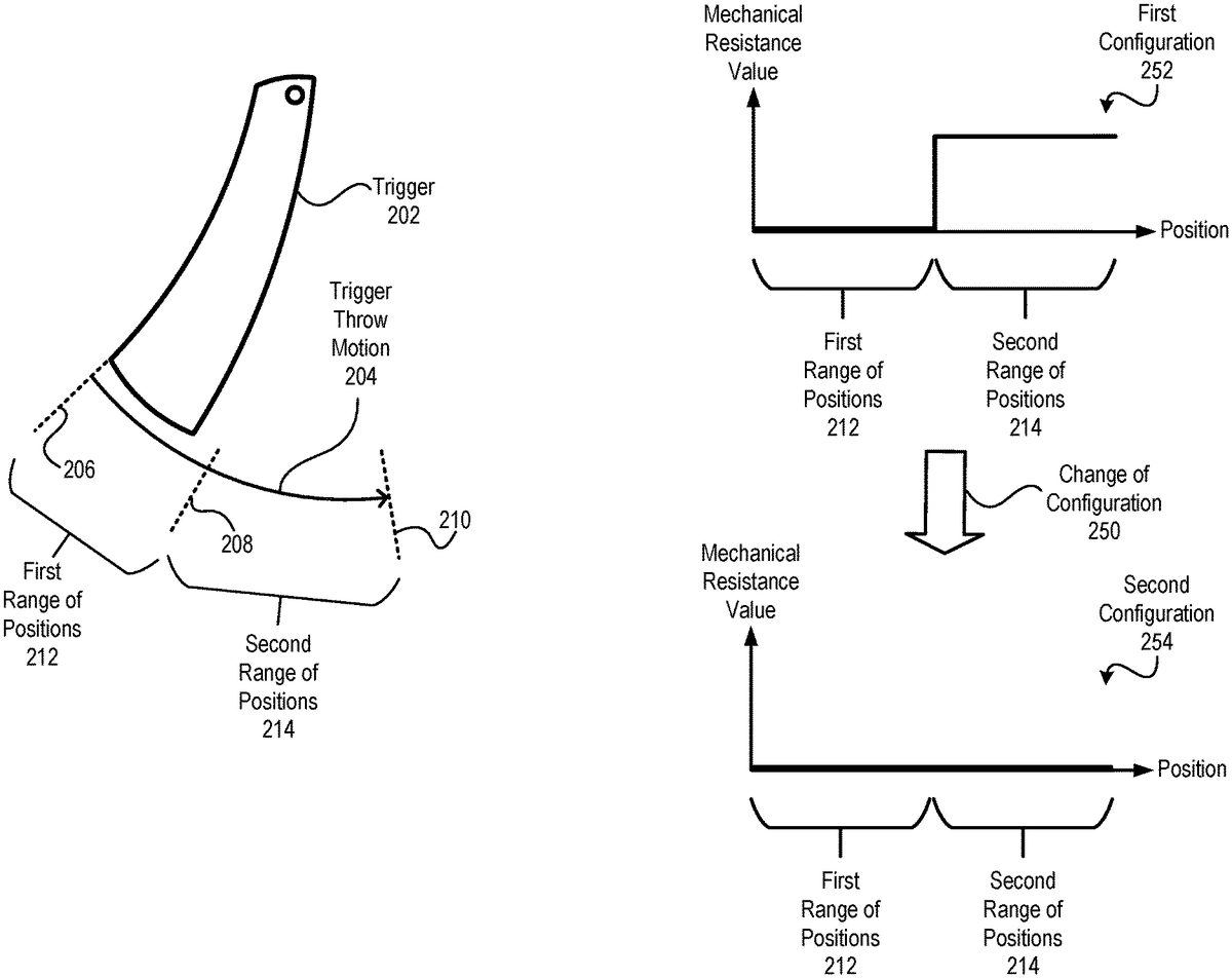
FIG.2illustrates an example of a change of configuration250of a trigger202from a first configuration252to a second configuration254according to some aspects of the disclosure. In some examples, the trigger202may correspond to or may be included in the input device152of the game controller150ofFIG.1. The first configuration252and the second configuration254may each be associated with an abscissa that may indicate positions of the trigger202and may each be associated with an ordinate that may indicate one or more mechanical resistance values corresponding to an adjustable resistance setting.
In some examples, the configuration142ofFIG.1may correspond to the first configuration252, and the second configuration254may correspond to another of the configurations124. In such examples, the mechanical resistance setting144may correspond to the mechanical resistance values specified by the first configuration252. In some other examples, the configuration142ofFIG.1may correspond to the second configuration254, and the first configuration252may correspond to another of the configurations124. In such examples, the mechanical resistance setting144may correspond to the mechanical resistance values (or value) specified by the second configuration254.
The trigger202may be movable within a set of positions corresponding to a trigger throw motion204. For example, the set of positions may include a position206, a position210, and positions from the position206to the position210. In some examples, the one or more positions146are selected from the set of positions corresponding to the trigger throw motion204.
The first configuration252may be associated with a first range of positions212(e.g., from the position206to a position208) and one or more first mechanical resistance values. The first configuration252may be associated with a second range of positions214(e.g., from the position208to the position210) and one or more second mechanical resistance values. In the example ofFIG.2, the first configuration252may include a “step” function, where the one or more first mechanical resistance values correspond to a first value (e.g., zero or approximately zero), and where the one or more second mechanical resistance values correspond to a second value greater than the first value. Other examples are also within the scope of the disclosure.
To illustrate, in some examples, a user may depress the trigger202through the first range of positions212with relatively little (or no) mechanical resistance. At the position208, the user may be met with an increase in mechanical resistance associated with the trigger202. In some implementations, pressing the trigger202through the first range of positions212may initiate a first operation associated with the video game application106, and pressing the trigger202through the second range of positions212may initiate a second operation associated with the video game application106. As a non-limiting example, the first operation may include “sighting” a target (such as by adding a crosshair, target overlay, or sniper scope to graphics content of the video game application106), and the second operation may include firing a weapon at the target. Other examples are also within the scope of the disclosure.
The second configuration254may be associated one or more different mechanical resistance values as compared to the first configuration252. For example, in the second configuration254, both the first range of positions212and the second range of positions214may be associated with the same mechanical resistance value (e.g., zero or approximately zero). As a non-limiting example, after a weapon is depleted of ammunition, the information handling system102may perform the change of configuration250from the first configuration252to the second configuration254. In such examples, the second configuration254of the trigger202may indicate to a user that the weapon is depleted of ammunition.
To further illustrate, in some aspects of the disclosure, the one or more positions146ofFIG.1may include one or more of a first position at which application of the mechanical resistance setting144takes effect (also referred to herein as a start position, home position, or rest position) and may further include a second position at which application of the mechanical resistance setting144ceases (also referred to herein as an end position or stop position). For example, the first position may correspond to the position208, and the second position may correspond to the position210.
In some aspects, the control signal140may indicate a change of the first position based on the gameplay event108, such as by changing the first position from one of the positions206,208to the other of the positions206,208. To illustrate, the gameplay event108may include receiving user input specifying a change of one type of weapon to another type of weapon, and the information handling system102may change the first position from one of the positions206,208to the other of the positions206,208via the control signal140. As a non-limiting example, a user may provide user input indicating a change from a first weapon with a first trigger feel (e.g., a trigger feel with less “slack” or “play”) to a second weapon with a second trigger feel (e.g., a trigger feel with more slack or play). In some such examples, the information handling system102may change the first position from the position206to the position208(e.g., to “firm up” the trigger202so that the trigger202has more slack in the trigger throw motion204).
Alternatively or in addition, the control signal140may indicate a change of the second position based on the gameplay event108, such as by changing the second position from one of the positions208,210to the other of the positions208,210. To illustrate, the gameplay event108may include receiving user input specifying a change of one type of weapon to another type of weapon, and the information handling system102may change the second position from one of the positions208,210to the other of the positions208,210via the control signal140. As a non-limiting example, a user may provide user input indicating a change from a weapon with a first trigger throw range (e.g., a hair trigger throw range) to a weapon with a second trigger throw range that is greater than the first trigger throw range. In some such examples, the information handling system102may change the first position from the position208to the position210(e.g., to increase a range of the trigger throw motion204from the first range of positions212to a combination of the first range of positions212and the second range of positions214).
Alternatively or in addition, the control signal140may indicate a change of the mechanical resistance setting144, such as by changing one or more mechanical resistance values applied by the adjustable resistance device154through at least some positions of the trigger throw motion204. To illustrate, the gameplay event108may include receiving user input specifying a change of one type of weapon to another type of weapon, and the information handling system102may change an amount of mechanical resistance applied through the trigger throw motion204via the control signal140. As a non-limiting example, a user may provide user input indicating a change from a first weapon with a first trigger feel (e.g., a “firm” trigger feel) to a second weapon with a second trigger feel (e.g., a “loose” trigger feel). In some such examples, the information handling system102may reduce (e.g., via the control signal140) an amount of mechanical resistance applied to the trigger202.
In some examples, the configuration142(or another configuration) may correspond to a “lock-out” of the trigger202. For example, the trigger202may be disabled based on unavailability of an item, such as running out of ammunition or a gun jam event.
By selecting the configuration142of the input device152based on the gameplay event108, user experience may be enhanced. For example, by changing the mechanical resistance setting144and the one or more positions146based on the gameplay event108, control of the input device152may “feel” more realistic to a user as compared to some other conventional devices, such as devices that do not change resistance or range of positions during gameplay. Further, the configuration142can be changed for different video games, which may enable a user to avoid purchasing multiple different types of game controllers for different video games.
FIG.3is a diagram illustrating an example of an adjustable resistance device300according to some aspects. In some examples, the adjustable resistance device300corresponds to the adjustable resistance device154ofFIG.1. The adjustable resistance device300may correspond to a friction brake device.
The adjustable resistance device300may include a shaft302and a shaft housing304that at least partially encloses (or houses) the shaft302. The shaft302may be coupled to or in contact with the input device152. For example, the shaft302may be coupled to or in contact with the trigger202ofFIG.2.
The adjustable resistance device300may further include a motor312, such as a servomotor. The motor312may be coupled to the controller156ofFIG.1, which may control operation of the motor312. The adjustable resistance device may further include a gear310coupled to the motor312, a first screw306(e.g., a left-threaded screw) coupled to the gear310, and a second screw308(e.g., a right-threaded screw) coupled to the gear310. In some examples, the first screw306and the second screw308may correspond to a set of counter rotating screws that are coupled to the shaft302(e.g., via a clamping band). The shaft302may apply mechanical resistance to the input device152(e.g., the trigger202) based on clamping force generated by the set of screws.
During operation, the motor312may rotate the gear310(e.g., based on a command from the controller156). The gear310may rotate the first screw306and the second screw308. Rotation of the first screw306and the second screw308may adjust a position of the shaft302.
The motor312may operate based on the configuration142indicated by the information handling system102. For example, an amount of mechanical resistance associated with the input device152may be changed by applying more or less force to the shaft via the motor312. To further illustrate, to increase the amount of mechanical resistance, the motor312may drive the first screw306and the second screw308in a first pair of directions (e.g., clockwise and counterclockwise, respectively), which may increase a clamping pressure applied to the shaft302. To decrease the amount of mechanical resistance, the motor312may drive the first screw306and the second screw308in a second pair of directions (e.g., counterclockwise and clockwise, respectively), which may decrease the clamping pressure applied to the shaft302.
As another example, the motor312may determine a start position or an end position of a range of positions (such as the positions of the trigger throw motion204) by “locking” or “clamping” the gear310in position. For example, to implement a trigger throw motion204having the first range of positions212, the motor312may inhibit the gear310from rotating outside the positions206,208(while allowing movement of the gear310in between the positions206,208). As another example, to implement a trigger throw motion204having the second range of positions214, the motor312may inhibit the gear310from rotating outside the positions208,210(while allowing movement of the gear310in between the positions208,210).
In some examples, implementation of the adjustable resistance device300ofFIG.3may enhance operation of a game controller, such as the game controller150. To illustrate, in some implementations, the adjustable resistance device300may enable application of a relatively large amount of mechanical resistance to the trigger202(e.g., by using the motor312to “lock” the first screw306and the second screw308in a position or in a range of positions). As a result, the adjustable resistance device300may enhance user experience during certain gameplay scenarios, such as gameplay scenarios in which the trigger202may be “locked” or disabled.
FIG.4is a diagram illustrating another example of an adjustable resistance device400according to some aspects. In some examples, the adjustable resistance device400corresponds to the adjustable resistance device154ofFIG.1. The adjustable resistance device400may correspond to an adjustable spring preload device.
The adjustable resistance device400may include a spring402(e.g., a torsion spring) and an actuator404(e.g., a servomotor) coupled to the spring402. The actuator404may be coupled to the controller156ofFIG.1. The spring402may be coupled to the input device152(such as the trigger202or another input device).
During operation, the actuator404may operate based on the configuration142indicated by the information handling system102. For example, the actuator404may cause deflection of the spring402based on the configuration142. The spring402may apply mechanical resistance to the input device152(such as the trigger202or another input device) based on the deflection. Further, in addition to applying mechanical resistance to force applied to the trigger202, the spring402may actively “push back” against the trigger202(e.g., to bias the trigger202in a particular position, such as the position206).
In some implementations, the actuator404is configured to adjust a position of the spring402to change a range of positions associated with the trigger202. To illustrate, the spring402may have a movable mounting position406that is adjustable by the actuator404. The actuator may cause deflection of the spring by adjusting the movable mounting position406(e.g., leftward or rightward inFIG.4) based on the configuration142, which may change an amount of preloaded force associated with the spring402.
In some examples, the adjustable resistance device400(or another adjustable resistance device described herein) may be used during an initialization or calibration stage (e.g., a “pre-game” calibration stage) of gameplay. For example, prior to playing a stage, a user may be prompted to calibrate the trigger202by applying force to the trigger202. The game controller150may detect an amount of force applied to the trigger202and may transmit a message to the information handling system102indicating the amount of force. In some implementations, receipt of the message by the information handling system102may correspond to the gameplay event108.
In some examples, implementation of the adjustable resistance device400ofFIG.4may enhance operation of a game controller, such as the game controller150. To illustrate, in some implementations, the adjustable resistance device400may change an amount of preloaded deflection associated with the spring402based on the movable mounting position406. Further, in addition to applying mechanical resistance to force applied to the trigger202, the spring402may actively “push back” against the trigger202(e.g., to bias the trigger202in a particular position, such as the position206). As a result, the adjustable resistance device400may enhance user experience during certain gameplay scenarios, such as gameplay scenarios in which the trigger202may be “biased” to one or more positions.
FIG.5is a diagram illustrating another example of an adjustable resistance device500and the trigger202according to some aspects. In some examples, the adjustable resistance device500corresponds to the adjustable resistance device154ofFIG.1. The adjustable resistance device500may correspond to a magnetorheological fluid (MRF) damper device.
The adjustable resistance device500may include an MRF brake502and a linkage structure504. The linkage structure504may be coupled to the MRF brake502and to the input device152(such as the trigger202or another input device).
During operation, the MRF brake502may operate based on the configuration142indicated by the information handling system102. For example, the MRF brake502may apply resistive torque to the input device152(such as the trigger202or another input device) via the linkage structure504based on the configuration142. In some examples, the MRF brake502may include a chamber, a fluid within the chamber, and particles (e.g., metal particles) disposed within the fluid. The MRF brake502may further include one or more coils that generate a magnetic field to magnetize the particles, which may solidify (or partially solidify) the fluid to generate mechanical resistance. Alternatively or in addition, the MRF brake502may generate haptic feedback events at the game controller150, such as by activating and deactivating the magnetic field based on a sequence or pattern. In some examples, the sequence or pattern is specified by the configuration142.
In some examples, implementation of the adjustable resistance device500ofFIG.5may enhance operation of a game controller, such as the game controller150. To illustrate, in some implementations, the adjustable resistance device500may enable dynamic change of feel of the trigger202and may further enable haptic feedback events at the game controller150.
FIG.6is a diagram illustrating another example of an adjustable resistance device600and the trigger202according to some aspects. In some examples, the adjustable resistance device600corresponds to the adjustable resistance device154ofFIG.1. The adjustable resistance device600may correspond to an MRF damper device.
The adjustable resistance device600may include an MRF brake602and a ring gear604. The ring gear604may be coupled to the MRF brake602and to the input device152(such as the trigger202or another input device).
During operation, the MRF brake602may operate based on the configuration142indicated by the information handling system102. For example, the MRF brake602may apply resistive torque to the input device152(such as the trigger202or another input device) via the ring gear604based on the configuration142. In some examples, the MRF brake602may include a chamber, a fluid within the chamber, and particles (e.g., metal particles) disposed within the fluid. The MRF brake602may further include one or more coils that generate a magnetic field to magnetize the particles, which may solidify (or partially solidify) the fluid to generate mechanical resistance. Alternatively or in addition, the MRF brake602may generate haptic feedback events at the game controller150, such as by activating and deactivating the magnetic field based on a sequence or pattern. In some examples, the sequence or pattern is specified by the configuration142.
In some examples, implementation of the adjustable resistance device600ofFIG.6may enhance operation of a game controller, such as the game controller150. To illustrate, in some implementations, the adjustable resistance device600may enable dynamic change of feel of the trigger202and may further enable haptic feedback events at the game controller150.
FIG.7is a diagram illustrating multiple views of another example of an adjustable resistance device700and the trigger202according to some aspects. In some examples, the adjustable resistance device700corresponds to the adjustable resistance device154ofFIG.1.
The example ofFIG.7illustrates that the adjustable resistance device700may include a bumper button702. In some examples, the bumper button702and the trigger202are coupled to (e.g., secured to) a frame706of the adjustable resistance device700. A pin support710may support one or more structures of the adjustable resistance device700. For example, the adjustable resistance device700may include an MRF brake714(e.g., the MRF brake602ofFIG.6, or another MRF brake), and the pin support710may be coupled to the MRF brake714(e.g., based on a snap-on attachment to the MRF brake714).
The adjustable resistance device700may further include a gear sleeve708. In some implementations, the gear sleeve708may constrain or limit motion of gear teeth704, such as by keeping the gear teeth704away from the MRF brake714(e.g., to a location where a pitch circle may be reduced). A frame706of the adjustable resistance device700may be coupled to a chassis of the game controller150. A clip support712may be coupled to the MRF brake714and to the frame706. The clip support712may be supported, at least in part, by the pin support710.
FIG.8is a flow chart of an example of a method800of operation of an information handling system according to some aspects. In some examples, the method800may be performed by the information handling system102ofFIG.1, such as by the processor104.
The method800may include detecting a game state update, at802. For example, the game state update may correspond to the gameplay event108. In some examples, the information handling system102may detect the game state update based on a determination that the one or more gameplay event criteria110are satisfied. As an illustrative example, the game state update may correspond to user selection of an item (e.g., a weapon) during gameplay of the video game application106. To further illustrate, the game state update may correspond to user selection of a firearm among different firearms each having one or more respective mechanical resistance values and each having a respective trigger throw range.
The method800may further include sending the game state update to an adaptive resistance engine, at804. For example, the processor104may send the game state update to the adaptive resistance engine112ofFIG.1to cause the adaptive resistance engine112to perform one or more operations described herein.
The method800may further include checking one or more active conditions, at806. The one or more active conditions may correspond to a set of one or more currently configured conditions associated with the input device152. In some implementations, the adaptive resistance engine112may maintain a state machine storing a value indicating the one or more currently configured conditions of the input device152.
For example, checking the one or more active conditions may include determining whether a first condition is satisfied, at808. In some examples, checking whether the first condition is satisfied may include determining whether a particular game condition is satisfied, such as if a user has obtained a weapon. If the first condition is satisfied, the method800may continue, at820. If the first condition is not satisfied, the method800may include setting (or removing) a start position associated with the trigger, at814, and the method800may continue, at820. To further illustrate, prior to the user selecting or obtaining a weapon during gameplay, the trigger202may be inoperable or “locked out” (e.g., where the user is unable to operate the trigger202due to a large amount of mechanical resistance at the beginning of the trigger throw motion204).
As another example, checking the one or more active conditions may include determining whether a second condition is satisfied, at810. In some examples, checking whether the second condition is satisfied may include determining whether a weapon has been selected or obtained. If the second condition is satisfied, the method800may continue, at820. If the second condition is not satisfied, the method800may include setting (or removing) a mechanical resistance setting associated with the trigger, at816, and the method800may continue, at820. To further illustrate, upon selecting or obtaining a weapon during gameplay, a force curve associated with the weapon may be provided to the game controller150.
As an additional example, checking the one or more active conditions may include determining whether a third condition is satisfied, at812. In some examples, checking whether the third condition is satisfied may include determining whether a weapon is out of ammunition. If the third condition is satisfied, the method800may continue, at820. If the third condition is not satisfied, the method800may include setting (or removing) an end position associated with the trigger, at818, and the method800may continue, at820. To illustrate, upon running out of ammunition, the adjustable resistance device154may reduce or remove mechanical resistance from the input device152(e.g., so that the trigger202feels “empty” or “loose”).
The method800may include updating the one or more active conditions, at820. For example, the adaptive resistance engine112may update state machine maintained by the adaptive resistance engine112from a first value indicating the previous conditions associated with the trigger202to a second value indicating the current conditions associated with the trigger202.
FIG.9is a flow chart of an example of another method900of operation of an information handling system according to some aspects. In some examples, the method800may be performed by the information handling system102ofFIG.1, such as by the processor104.
The method900includes detecting, by the information handling system during execution of a video game application, a gameplay event associated with the video game application, at902. For example, the information handling system102may detect the gameplay event108.
The method900further includes determining, by the information handling system, a mechanical resistance setting associated with an input device of a game controller, at904. The mechanical resistance setting is associated with the gameplay event. For example, the information handling system102may determine the mechanical resistance setting144based on the gameplay event108.
The method900further includes determining, by the information handling system, one or more positions of the input device at which the mechanical resistance setting is to be applied, at906. The mechanical resistance setting is associated with the gameplay event. For example, the information handling system102may determine the one or more positions146based on the gameplay event108.
The method900further includes sending, by the information handling system to the game controller, a control signal indicating a configuration of the input device, at908. The configuration is associated with the mechanical resistance setting and the one or more positions. For example, the information handling system102may sent the control signal140to the game controller150to indicate the configuration142.
The method900may further include receiving, by the information handling system and from the game controller, user input associated with the video game application, where the user input is received via the input device based on the configuration. For example, the information handling system102may receive the user input170from the game controller150via the interface130, where the user input170is received by the game controller150via the input device152and based on the configuration142.
FIG.10is a flow chart of an example of a method1000of operation of a game controller according to some aspects. In some examples, the method800may be performed by the game controller150ofFIG.1.
The method1000may include receiving a control signal indicating a configuration of an input device, at1002. The configuration is associated with a mechanical resistance setting of the input device and is further associated with one or more positions of the input device. For example, the game controller150may receive the control signal140indicating the configuration142of the input device152, and the configuration142may be associated with the mechanical resistance setting144and the one or more positions146.
The method1000may further include applying the mechanical resistance setting to the input device via an adjustable resistance device based on the one or more positions, at1004. For example, the game controller150may apply the mechanical resistance setting to the input device152(or the trigger202) via any of the adjustable resistance devices154,300,400,500,600, or700based on the one or more positions146.
The method1000may further include receiving user input via the input device based on the configuration, at1006. For example, a user may pull the trigger202through a range of positions, such as the first range of positions212, the second range of positions214, or a combination of the first range of positions212and the second range of positions214to generate the user input170, which may be detected by the controller156.
The method1000may optionally include transmitting the user input to the information handling system102. For example, the controller156may initiate transmission of the user input170to the information handling system102via the interface158.
Although certain aspects of the disclosure are described separately for convenience, it is noted that some aspects may be combined without departing from the scope of the disclosure. For example, in some implementations, an adjustable resistance may include any combination of features described with reference to the adjustable resistance devices154,300,400,500,600, and700. Those of skill in the art will appreciate that other such examples are also within the scope of the disclosure.
In some implementations, one or more operations described above as performed by a system, server, controller, or other device may be performed by any circuit configured to perform the described operations. Such a circuit may be an integrated circuit (IC) constructed on a semiconductor substrate and include logic circuitry, such as transistors configured as logic gates, and memory circuitry, such as transistors and capacitors configured as dynamic random access memory (DRAM), electronically programmable read-only memory (EPROM), or other memory devices. The logic circuitry may be configured through hard-wire connections or through programming by instructions, which may be contained in software, such as firmware. Further, the logic circuitry may be configured as a general purpose processor capable of executing instructions contained in software and/or firmware. If implemented in firmware and/or software, functions described above may be stored as one or more instructions or code on a computer-readable medium. Examples include non-transitory computer-readable media encoded with a data structure and computer-readable media encoded with a computer program. Computer-readable media includes physical computer storage media. A storage medium may be any available medium that can be accessed by a computer. By way of example, and not limitation, such computer-readable media can comprise random access memory (RAM), read-only memory (ROM), electrically-erasable programmable read-only memory (EEPROM), compact disc read-only memory (CD-ROM) or other optical disk storage, magnetic disk storage or other magnetic storage devices, or any other medium that can be used to store desired program code in the form of instructions or data structures and that can be accessed by a computer. Disk and disc includes compact discs (CD), laser discs, optical discs, digital versatile discs (DVD), floppy disks and Blu-ray discs. Generally, disks reproduce data magnetically, and discs reproduce data optically. Combinations of the above should also be included within the scope of computer-readable media.
In addition to storage on computer readable medium, instructions and/or data may be provided as signals on transmission media included in a communication apparatus. For example, a communication apparatus may include a transceiver having signals indicative of instructions and data. The instructions and data are configured to cause one or more processors to implement the functions outlined in the claims.
Although the present disclosure and certain representative advantages have been described in detail, it should be understood that various changes, substitutions and alterations can be made herein without departing from the scope of the disclosure as defined by the appended claims. Moreover, the scope of the present application is not intended to be limited to the particular embodiments of the process, machine, manufacture, composition of matter, means, methods and steps described in the specification. For example, although certain processors (e.g., the processor104, the controller156, or both) have been described, aspects may be executed on different kinds of processors, such as graphics processing units (GPUs), central processing units (CPUs), and digital signal processors (DSPs). As another example, although processing of certain kinds of data may be described in example embodiments, other kinds or types of data may be processed through the methods and devices described above. As one of ordinary skill in the art will readily appreciate from the present disclosure, processes, machines, manufacture, compositions of matter, means, methods, or steps, presently existing or later to be developed that perform substantially the same function or achieve substantially the same result as the corresponding embodiments described herein may be utilized. Accordingly, the appended claims are intended to include within their scope such processes, machines, manufacture, compositions of matter, means, methods, or steps.
Claims
- An information handling system comprising: a memory;and a processor coupled to the memory and configured to: detect, during execution of a video game application, a gameplay event associated with the video game application;determine a mechanical resistance setting associated with an input device of a game controller, wherein the mechanical resistance setting is associated with the gameplay event;determine one or more positions of the input device at which the mechanical resistance setting is to be applied, the one or more positions including a first position of the input device at which application of the mechanical resistance setting is to take effect;and send, to the game controller, a control signal indicating a configuration of the input device, wherein the configuration indicates the mechanical resistance setting and the one or more positions.
- The information handling system of claim 1, wherein the processor is further configured to receive, from the game controller, user input associated with the video game application via the input device based on the configuration.
- The information handling system of claim 1, wherein the one or more positions further include a second position at which the application of the mechanical resistance setting is to cease.
- The information handling system of claim 1, wherein the control signal indicates a change of the first position based on the gameplay event.
- The information handling system of claim 3, wherein the control signal indicates a change of the second position based on the gameplay event.
- The information handling system of claim 3, wherein the control signal indicates changes of both the first position and the second position based on the gameplay event.
- The information handling system of claim 1, wherein the input device includes or corresponds to a trigger, wherein the one or more positions are selected from a set of positions corresponding to a trigger throw motion of the trigger, and wherein the mechanical resistance setting indicates one or more mechanical resistance values as a function of position of the trigger.
- The information handling system of claim 1, wherein the control signal indicates a change of the mechanical resistance setting based on the gameplay event.
- The information handling system of claim 1, wherein the memory is configured to store mechanical resistance mapping data indicating a plurality of gameplay events including the gameplay event and further indicating a plurality of configurations associated with the plurality of gameplay events, the plurality of configurations including the configuration.
- The information handling system of claim 9, wherein the processor is further configured to: access the mechanical resistance mapping data;and based on the gameplay event, select the configuration from the plurality of configurations.
- The information handling system of claim 1, wherein the configuration is associated with a first range of positions and a second range of positions, wherein pressing the input device through the first range of positions initiates a first operation associated with the video game application, and wherein pressing the input device through the second range of positions initiates a second operation associated with the video game application that is different than the first operation.
- The information handling system of claim 1, wherein the input device is included in a game controller that further includes a magnetorheological fluid (MRF) brake coupled to the input device via a linkage structure, and wherein the MRF brake is configured to apply resistive torque to the input device via the linkage structure based on the configuration.
- The information handling system of claim 1, wherein the input device is included in a game controller that further includes a magnetorheological fluid (MRF) brake coupled to the input device via a ring gear, and wherein the MRF brake is configured to apply resistive torque to the input device via the ring gear based on the configuration.
- A method comprising: detecting, by an information handling system during execution of a video game application, a gameplay event associated with the video game application;determining, by the information handling system, a mechanical resistance setting associated with an input device of a game controller, wherein the mechanical resistance setting is associated with the gameplay event;determining, by the information handling system, one or more positions of the input device at which the mechanical resistance setting is to be applied, the one or more positions including a first position of the input device at which application of the mechanical resistance setting is to take effect;and sending, by the information handling system to the game controller, a control signal indicating a configuration of the input device, wherein the configuration indicates the mechanical resistance setting and the one or more positions.
- The method of claim 14, wherein the one or more positions further include a second position at which the application of the mechanical resistance setting is to cease, and wherein the control signal indicates changes of both the first position and the second position based on the gameplay event.
Disclaimer: Data collected from the USPTO and may be malformed, incomplete, and/or otherwise inaccurate.