U.S. Pat. No. 11,980,808
GAME CONTROLLER AND FORM TRANSFORMATION METHOD THEREOF, AND GAME OPERATION MODE SWITCHING METHOD
Issue DateJuly 13, 2021
Illustrative Figure
Abstract
The present disclosure discloses a game controller, including a gun-shaped body, a mode switching mechanism, a gamepad, and a screen positioning device arranged on the gun-shaped body. The mode switching mechanism switches different game operation modes; and the gamepad is rotatably connected to the gun-shaped body. The present disclosure can adapt to most games in the market, which can not only enhance the vicarious feeling of a game, but also provide a more comprehensive operation experience for a user.
Description
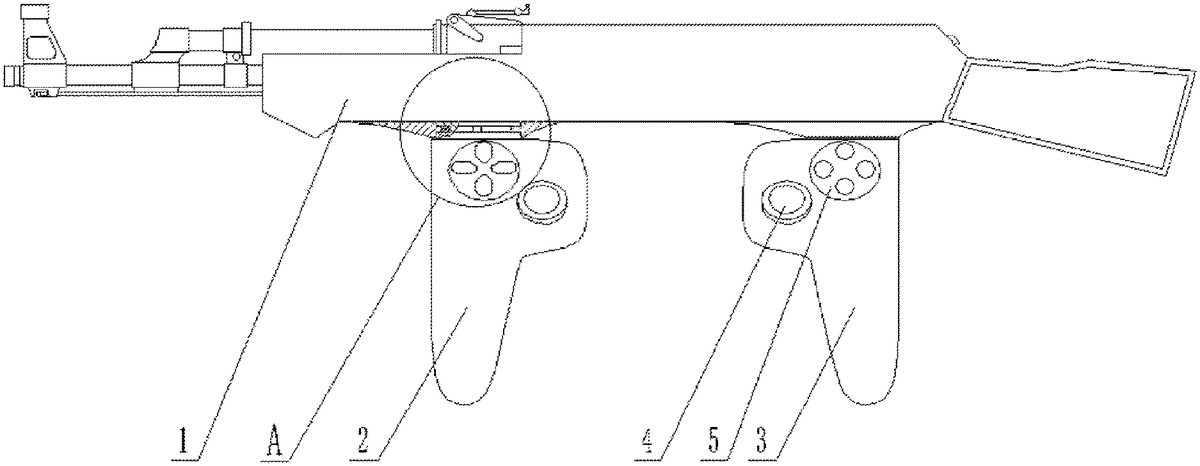
REFERENCE SIGNS IN DRAWINGS 1: gun-shaped body;2: front gamepad;3: rear gamepad;4: rocker;5: function control button;6: rotating shaft;7: sleeve;8: ring slot;9: snap ring;10: first magnet;11: second magnet;12: first arc-shaped contact sheet;13: second arc-shaped contact sheet;14: direction control button;15: gun-shaped main body;16: clamping protrusion;17: clamping slot;18: clamping groove;19: clamping block;20: accommodating hole;21: clamping ring;22: spring;23: function control button A;24: function control button B;25: function control button X;26: function control button Y;27: independent button; and28: clamping body.α: included angle between connection lines of two first magnets and the axis of a rotating shaft; β: an included angle between connecting lines of a first arc-shaped contact sheet as well as a second arc-shaped contact sheet and the axis of the rotating shaft; γ: an included angle between a gamepad and a gun-shaped body. DETAILED DESCRIPTION OF THE EMBODIMENTS The embodiments of the present disclosure is described in detail below in combination with the accompanying drawings. Embodiment 1 A game controller as shown inFIG.1toFIG.2includes a gun-shaped body1, a mode switching mechanism, a screen positioning device and two gamepads. The gun-shaped body1is of a gun shape; the two gamepads are located at the lower part of the gun-shaped body1, and include a front gamepad2and a rear gamepad3(a muzzle of the gun-shaped body1inFIG.1is leftward, i.e., a left end of the gun-shaped body1is a front end, and a right end of the gun-shaped body1is a rear end); and the front gamepad2is located on the left side of the rear gamepad3. Game control devices are arranged on both the front gamepad2and the rear gamepad3, and the game control device on the front gamepad2includes a direction control button14and a rocker4. As shown inFIG.7toFIG.8, the game control device on the rear gamepad3includes a function control button5and a rocker4. The screen positioning device includes a camera and an infrared light-transmittance sheet which ...
REFERENCE SIGNS IN DRAWINGS
1: gun-shaped body;2: front gamepad;3: rear gamepad;4: rocker;5: function control button;6: rotating shaft;7: sleeve;8: ring slot;9: snap ring;10: first magnet;11: second magnet;12: first arc-shaped contact sheet;13: second arc-shaped contact sheet;14: direction control button;15: gun-shaped main body;16: clamping protrusion;17: clamping slot;18: clamping groove;19: clamping block;20: accommodating hole;21: clamping ring;22: spring;23: function control button A;24: function control button B;25: function control button X;26: function control button Y;27: independent button; and28: clamping body.α: included angle between connection lines of two first magnets and the axis of a rotating shaft; β: an included angle between connecting lines of a first arc-shaped contact sheet as well as a second arc-shaped contact sheet and the axis of the rotating shaft; γ: an included angle between a gamepad and a gun-shaped body.
DETAILED DESCRIPTION OF THE EMBODIMENTS
The embodiments of the present disclosure is described in detail below in combination with the accompanying drawings.
Embodiment 1
A game controller as shown inFIG.1toFIG.2includes a gun-shaped body1, a mode switching mechanism, a screen positioning device and two gamepads. The gun-shaped body1is of a gun shape; the two gamepads are located at the lower part of the gun-shaped body1, and include a front gamepad2and a rear gamepad3(a muzzle of the gun-shaped body1inFIG.1is leftward, i.e., a left end of the gun-shaped body1is a front end, and a right end of the gun-shaped body1is a rear end); and the front gamepad2is located on the left side of the rear gamepad3. Game control devices are arranged on both the front gamepad2and the rear gamepad3, and the game control device on the front gamepad2includes a direction control button14and a rocker4. As shown inFIG.7toFIG.8, the game control device on the rear gamepad3includes a function control button5and a rocker4. The screen positioning device includes a camera and an infrared light-transmittance sheet which are mounted at the front end of the gun-shaped body.
The upper ends of the two gamepads are connected with the gun-shaped body1through a rotation part. As shown inFIG.3, the rotation part includes a rotating shaft6and a sleeve7sleeved on the rotating shaft6. An outer wall of the rotating shaft6is provided with a ring slot8in a circumferential direction; an inner wall of the sleeve7is snapped to a snap ring9in the ring slot8; and the rotating shaft6and the sleeve7are fixedly connected to the gamepad and the gun-shaped body1respectively. Two first magnets10are embedded into a surface of the snap ring9; as shown inFIG.4, connecting lines between the two first magnets10and the axis of the rotating shaft6are perpendicular to each other (i.e., α inFIG.4is 90 degrees); and two second magnets11matching the first magnets10are embedded into an inner surface of the ring slot8. Different magnetic poles of the first magnets10and the second magnets11are opposite.
As shown inFIG.3toFIG.4, the mode switching mechanism is arranged between the snap ring9and the ring slot8in the front gamepad2. The mode switching mechanism is a mechanical switch, which can switch two different game operation modes, i.e., a gamepad operation mode and a gun operation mode. The mode switching mechanism is in communication connection with a processor arranged inside the gun-shaped body1(the processor and a connection manner for the processor and the mode switching mechanism are both existing, such as a processor disclosed in the Chinese utility model patent No. CN2778350). The processor communicates with game software. The processor may execute an operation to determine whether a user selects the gamepad operation mode or the gun operation mode, and use the gamepad operation mode or the gun operation mode of the game control device according to the selection of the user.
As shown inFIG.3toFIG.4, the mode switching mechanism specifically includes a first arc-shaped contact sheet12and a second arc-shaped contact sheet13. The first arc-shaped contact sheet12and the second arc-shaped contact sheet13are located on the same horizontal plane; and connecting lines between the first arc-shaped contact sheet12as well as the second arc-shaped contact sheet13and the axis of the rotating shaft6are perpendicular to each other (i.e., β inFIG.4is 90 degrees). The first arc-shaped contact sheet12and the second arc-shaped contact sheet13are respectively embedded into the surfaces of the snap ring9and the ring slot8.
A working principle of the above-mentioned game controller is as follows.
In the gamepad operation mode, a user operates the front gamepad2and the rear gamepad3respectively with a left hand and a right hand. The gamepad operation mode is the existing operation mode, such as a gamepad operation mode in xbox and PlayStation. At this time, the two corresponding pairs of first magnets10and second magnets11attract each other to ensure the stability of the two gamepads in the gamepad operation mode. At the same time, the first arc-shaped contact sheet12and the second arc-shaped contact sheet13are in no contact, and the mechanical switch is not closed. At this time, the processor determines that the user selects the gamepad operation mode and transmits information to the game software. The game software uses the gamepad operation mode for the user to operate.
In the gun operation mode, after the front gamepad2and the rear gamepad3are anticlockwise rotated 90 degrees, the shape of the game controller is as shown inFIG.5. At this time, only one pair of first magnet10and second magnet11attract each other to ensure the stability of the two gamepads in the gun operation mode. At the same time, the first arc-shaped contact sheet12and the second arc-shaped contact sheet13are in contact, as shown inFIG.6, and the mechanical switch is closed. At this time, the processor determines that the user selects the gun operation mode and transmits information to the game software. The game software uses the gun operation mode for the user to operate. The gun operation mode is an existing operation mode, such as a gun operation mode in xbox and PlayStation, and screen aiming positioning equipment is added. For example, according to an infrared light gun positioning method and system disclosed in China invention patent (publication No. CN103949054A), an operation mode is specifically as follows. Four infrared light emitting points are mounted at four corners of a screen; and the front end of the gun-shaped body is provided with a camera and an infrared light-transmittance sheet. The user plays a game in a posture of holding a gun. The user presses the function control button to control the camera to collect images of the infrared light emitting points, and an aiming position of the gun body is calculated by means of image identification and an algorithm.
Meanwhile, in order to improve the comfortableness of user's use of the gamepad, an included angle of 60 degrees (i.e., γ inFIG.5is 60 degrees) is reserved between the gamepad and the gun-shaped body1.
The above-mentioned game controller has the advantages that transformation of the form of the game controller is combined with switching of the game operation modes, so that different operation modes can be switched according to user's needs by rotating the gamepad. Meanwhile, after the gamepad is rotated, the game controller can simulate user's use of a real firearm to play a game, which enhances the vicarious feeling of a game and provides a more comprehensive operation experience for the user.
Embodiment 2
As shown inFIG.9, Embodiment 2 is improved on the basis of Embodiment 1. The gun-shaped body1in Embodiment 2 is cuboid. As such, the game operation mode is still the gun operation mode, but the gun-shaped body1does not simulate the appearance of a firearm, which is easy to manufacture and low in cost.
Other structures and the working principle of Embodiment 2 are the same as Embodiment 1.
Embodiment 3
Embodiment 3 is improved on the basis of Embodiment 1. Specifically, in Embodiment 3, an inner wall of the sleeve7is provided with a ring slot8in a circumferential direction, and an outer wall of the rotating shaft6is provided with a snap ring9snapped to the ring slot8. As such, reliable rotatable connection between the sleeve7and the rotating shaft6can still be ensured.
Other structures and the working principle of Embodiment 3 are the same as Embodiment 1.
Embodiment 4
As shown inFIG.10toFIG.12, Embodiment 4 is improved on the basis of Embodiment 1. The gun-shaped body1in Embodiment 4 includes a gun-shaped main body15and a clamping body28detachably connected to the gun-shaped main body15. A screen positioning device is arranged on the gun-shaped main body15, and the lower part of the gun-shaped body1is provided with a snap slot matching the shape of the clamping body28. As shown inFIG.13, the upper ends of the two gamepads are rotatably connected to the clamping body28respectively; the right end of the clamping body28is provided with a clamping slot17; and a position of the gun-shaped body1facing the clamping slot17is provided with a clamping protrusion16. A clamping groove18is formed in a left end surface of the clamping body28; a position of the gun-shaped body1facing the clamping groove18is provided with an accommodating hole20; the accommodating hole20is a stepped hole, and a clamping block19is arranged in the accommodating hole20; the right end of the clamping block19extends rightward out of the accommodating hole20and is clamped into the clamping groove18; and the left end of the clamping block19runs through the accommodating hole20and extends out of the gun-shaped body1. The clamping block19is fixedly connected with a clamping ring21; the clamping ring21is restrained in the accommodating hole20; a spring22is arranged between the clamping ring21and the accommodating hole20; and the spring22is sleeved on the clamping block19.
A user shifts the right end of the clamping block19to the right to separate the clamping block19from the clamping groove18, that is, the clamping body28may be removed from a side surface of the gun-shaped main body15(that is, the clamping body28is removed from a direction perpendicular to the drawing inFIG.10). After the clamping body28is removed, the user can play a game in a gamepad form conveniently. When the user intends to play a game in a gun form, the user only needs to clamp the clamping body28to the gun-shaped main body15, which is extremely convenient.
Other structures and the working principle of Embodiment 4 are the same as Embodiment 1.
Embodiment 5
As shown inFIG.14toFIG.15, Embodiment 5 is improved on the basis of Embodiment 1. A difference between Embodiment 5 and Embodiment 1 is that the mode switching mechanism is changed. Specifically, the mechanical switch arranged between the snap ring9and the ring slot8in the front gamepad2is canceled, and a function control button B24on the rear gamepad3is used as a mode switching mechanism. As such, transformation of the form of the game controller and switching of the game operation modes are separated. After the user rotates the gamepad to transform the form of the gamepad, the game operation mode may not be automatically switched (that is, after the user rotates the gamepad, the game operation mode cannot be switched until the function control button B24is pressed).
The game controller in Embodiment 5 has the advantages that the user presses the function control button B24and rotates the gamepad to simulate user's use of a real firearm to play a game, which enhances the vicarious feeling of the game and provides a more comprehensive operation experience for the user.
Other structures and the working principle of Embodiment 5 are the same as Embodiment 1.
Embodiment 6
As shown inFIG.16, Embodiment 6 is improved on the basis of Embodiment 1. A difference between Embodiment 6 and Embodiment 1 is that the mode switching mechanism is changed. Specifically, the mechanical switch arranged between the snap ring9and the ring slot8in the front gamepad2is canceled, and an independent button27on the rear gamepad3is used as a mode switching mechanism. As such, transformation of the form of the game controller and switching of the game operation modes are separated. After the user rotates the gamepad to transform the form of the gamepad, the game operation mode may not be automatically switched (that is, after the user rotates the gamepad, the game operation mode cannot be switched until the independent button27is pressed). In this way, compared with Embodiment 5, the present embodiment takes the independent button27as an independent mode switching mechanism, so that an original game function of the function control button B24cannot be occupied.
Other structures and the working principle of Embodiment 6 are the same as Embodiment 1.
Embodiment 7
As shown inFIG.17toFIG.18, Embodiment 7 is improved on the basis of Embodiment 1. A difference between Embodiment 7 and Embodiment 1 is that the structure of the rotation part is changed. Specifically, the rotating shaft6is changed into a drum shape, and the inner wall of the sleeve7is changed into a drum shape matching the rotating shaft6.
Other structures and the working principle of Embodiment 7 are the same as Embodiment 1.
Embodiment 8
As shown inFIG.19toFIG.20, Embodiment 8 is improved on the basis of Embodiment 1. A difference between Embodiment 8 and Embodiment 1 is that the structure of the rotation part is changed. Specifically, the rotating shaft6is changed into an inverted cone shape, and the inner wall of the sleeve7is changed into an inverted cone shape matching the rotating shaft6.
Other structures and the working principle of Embodiment 8 are the same as Embodiment 1.
Embodiment 9
Embodiment 9 uses the equipment structure in Embodiment 1 to play a game. A specific game is PLAYERUNKNOWN'S BATTLEGROUNDS. When a user manipulates a virtual character to explore a game map and pick up equipment, a gamepad operation mode is used to play the game. When the user manipulates the virtual character to raise the gun to aim and shoot, a gun operation mode is used to play the game. In the gun operation mode, what is different from a traditional moving screen image is that a center point of the screen image is taken as a shooting point. Gamepad function buttons are used to move and rotate a game image, and a screen positioning point captured by a positioning system is a game shooting point to simulate a real shooting feeling. Images during shooting are similar to Virtua Cop.
As such, the user can use different operation modes to play a game in the same game, and the user can switch the operation mode back and forth between the gun operation mode and the gamepad operation mode, so as to avoid phenomena of anchylosis and muscular soreness and further enhance the operation experience of the user.
The above-mentioned embodiments only express several implementation modes of the present disclosure, and their descriptions are more specific and detailed, but they cannot be understood as limiting the patent scope of the present disclosure. It should be noted that those of ordinary skill in the art can further make various transformations and improvements without departing from the concept of the disclosure, and these transformations and improvements all fall within the protection scope of the present disclosure.
Claims
- A game controller, comprising a gun-shaped body, a mode switching mechanism, a gamepad, and a screen positioning device arranged on the gun-shaped body, wherein the mode switching mechanism switches different game operation modes, and the gamepad is rotatably connected to the gun-shaped body, wherein the gamepad is connected with the gun-shaped body through a rotation part;and wherein the rotation part comprises a rotating shaft and a sleeve sleeved on the rotating shaft;an outer wall of the rotating shaft is provided with a ring slot in a circumferential direction;an inner wall of the sleeve is snapped to a snap ring in the ring slot;and the rotating shaft and the sleeve are fixedly connected to the gamepad and the gun-shaped body respectively.
- The game controller according to claim 1, wherein the mode switching mechanism is controlled to realize switching by a rotation position of the gamepad.
- The game controller according to claim 1, wherein two first magnets are embedded into a surface of the snap ring;connecting lines between the two first magnets and the axis of the rotating shaft are perpendicular to each other;and second magnets matching the first magnets are embedded into an inner surface of the ring slot.
- The game controller according to claim 3, wherein the mode switching mechanism is arranged between the snap ring and the ring slot;the mode switching mechanism comprises a first arc-shaped contact sheet and a second arc-shaped contact sheet;connecting lines between the first arc-shaped contact sheet as well as the second arc-shaped contact sheet and the axis of the rotating shaft are perpendicular to each other;and the first arc-shaped contact sheet and the second arc-shaped contact sheet are respectively embedded to the surfaces of the snap ring and the ring slot.
- A form transformation method for a game controller, wherein the transformation method realizes transformation by rotating a gamepad, wherein the gamepad is connected with a gun-shaped body through a rotation part;and wherein the rotation part comprises a rotating shaft and a sleeve sleeved on the rotating shaft;an outer wall of the rotating shaft is provided with a ring slot in a circumferential direction;an inner wall of the sleeve is snapped to a snap ring in the ring slot;and the rotating shaft and the sleeve are fixedly connected to the gamepad and the gun-shaped body respectively.
- The form transformation method for the game controller according to claim 5, wherein the transformation method transforms the game controller into a gamepad form or a gun form by rotating the gamepad.
- A game operation mode switching method, wherein the switching method realizes switching by rotating a gamepad, wherein the gamepad is connected with a gun-shaped body through a rotation part;and wherein the rotation part comprises a rotating shaft and a sleeve sleeved on the rotating shaft;an outer wall of the rotating shaft is provided with a ring slot in a circumferential direction;an inner wall of the sleeve is snapped to a snap ring in the ring slot;and the rotating shaft and the sleeve are fixedly connected to the gamepad and the gun-shaped body respectively.
- The game operation mode switching method according to claim 7, wherein the switching method rotates the gamepad to trigger a mode switching mechanism to realize switching.
Disclaimer: Data collected from the USPTO and may be malformed, incomplete, and/or otherwise inaccurate.