U.S. Pat. No. 11,978,166
TOY SYSTEM FOR ASYMMETRIC MULTIPLAYER GAME PLAY
AssigneeLEGO A/S
Issue DateJune 24, 2022
Illustrative Figure
Abstract
According to one aspect, a toy system is adapted for use in a multiplayer game, the toy system comprising a primary user device, a secondary user device, and one or more toys; wherein the primary and secondary user devices are operable in a common multiplayer game session; wherein the primary user device is configured to capture video images of a real-world scene including the one or more toys from a primary view point and to display the captured video images as a primary view of the real-world scene; wherein the secondary user device is configured to display a secondary view of a scene corresponding to the real-world scene as seen from a secondary view point; wherein the one or more toys comprise at least one user-manipulable object adapted to selectively be brought into a user-selected one of a plurality of predetermined states, at least a first one of the predetermined states having a first visual appearance; wherein the primary user device is configured to detect said first predetermined state in a primary view including the user-manipulable object, based on the first visual appearance; and wherein the secondary user device is configured to produce user-perceptible output, in response to the detected first predetermined state. Corresponding methods and computer systems for implementing the method are also provided.
Description
DETAILED DESCRIPTION Various aspects and embodiments of toy construction systems disclosed herein will now be described with reference to modular toy elements in the form of bricks. However, the invention may be applied to other forms of toy construction elements and other forms of toys. FIG.1shows a modular toy element with coupling pegs on its top surface and a cavity extending into the brick from the bottom. The cavity has a central tube, and coupling pegs on another brick can be received in the cavity in a frictional engagement as disclosed in U.S. Pat. No. 3,005,282.FIGS.2and3show other such prior art modular toy elements. The modular toy elements shown in the remaining figures have this known type of coupling members in the form of cooperating pegs and cavities. However, other types of coupling members may also be used in addition to or in-stead of the pegs and cavities. The coupling pegs are arranged in a square planar grid, i.e. defining orthogonal directions along which sequences of coupling pegs are arranged. The distance between neighboring coupling pegs is uniform and equal in both directions. This or similar arrangements of coupling members at coupling locations defining a regular planar grid allow the modular toy elements to be interconnected in a discrete number of positions and orientations relative to each other, in particular at right angles with respect to each other. The modular toy elements shown here, inFIGS.1-3, are of the passive type, without additional functionality beyond mechanical model building, such as electromagnetic, electronic, optical, or the like. However, some embodiments of toy construction sets may also include active modular toy elements that are configured to perform user perceptual functions, e.g. emit light, sound, impart motion, etc. FIG.4shows schematically an embodiment of a toy system100as disclosed herein. The toy system100is adapted for use in ...
DETAILED DESCRIPTION
Various aspects and embodiments of toy construction systems disclosed herein will now be described with reference to modular toy elements in the form of bricks. However, the invention may be applied to other forms of toy construction elements and other forms of toys.
FIG.1shows a modular toy element with coupling pegs on its top surface and a cavity extending into the brick from the bottom. The cavity has a central tube, and coupling pegs on another brick can be received in the cavity in a frictional engagement as disclosed in U.S. Pat. No. 3,005,282.FIGS.2and3show other such prior art modular toy elements. The modular toy elements shown in the remaining figures have this known type of coupling members in the form of cooperating pegs and cavities. However, other types of coupling members may also be used in addition to or in-stead of the pegs and cavities. The coupling pegs are arranged in a square planar grid, i.e. defining orthogonal directions along which sequences of coupling pegs are arranged. The distance between neighboring coupling pegs is uniform and equal in both directions. This or similar arrangements of coupling members at coupling locations defining a regular planar grid allow the modular toy elements to be interconnected in a discrete number of positions and orientations relative to each other, in particular at right angles with respect to each other. The modular toy elements shown here, inFIGS.1-3, are of the passive type, without additional functionality beyond mechanical model building, such as electromagnetic, electronic, optical, or the like. However, some embodiments of toy construction sets may also include active modular toy elements that are configured to perform user perceptual functions, e.g. emit light, sound, impart motion, etc.
FIG.4shows schematically an embodiment of a toy system100as disclosed herein. The toy system100is adapted for use in an augmented reality enhanced asymmetric multiplayer game. The toy system100comprises a primary user device110for use by a primary user, a secondary user device120for use by a secondary user, and one or more physical toys131placed in a real-world scene130. The primary and secondary user devices110,120are operable to join in a common multiplayer game session140. The primary user device110is configured to capture video images of the real-world scene130including the one or more toys131from a primary view point111and to display the captured video images as a primary view112of the real-world scene130. The secondary user device120is configured to display a secondary view122of a scene corresponding to the real-world scene130as seen from a secondary view point, which in the example ofFIG.4is the point of view of a playable character92associated with the secondary user. The one or more toys131comprise at least one user-manipulable object150adapted to selectively be brought into a user-selected one of a plurality of predetermined states, i.e. at least two predetermined states151,152,153,154. In at least a first one151of the predetermined states151,152,153,154the user-manipulable object150has a first visual appearance, whereby it is recognizable when the user-manipulable object150is in the first state151. The primary user device110is configured to analyze the captured video images with respect to the first visual appearance of the user-manipulable object150so as to detect said first predetermined state151as a current user-selected state of the user-manipulable object150in a primary view112including the user-manipulable object150, based on a recognition of the first visual appearance. Information indicative of the detected first predetermined state151may then be provided to the secondary user device120. The secondary user device120may then produce user-perceptible output, in response to said information indicative of the detected first predetermined state151.
For example, the toy system may comprise a primary tablet computer110having stored thereon an augmented reality (AR) App executing an AR-based digital game application. The primary tablet computer110may comprise a display and a digital camera. The primary tablet computer may further comprise a processing unit executing the AR App and a storage medium for storing game-related data. It will be appreciated that, instead of a tablet computer, the toy system may include another type of suitably programmed data processing device or system as the primary user device110, including a display, a processing unit, and an image capture device. Examples of suitable primary data processing systems include a personal computer, a desktop computer, a laptop computer, a handheld computer, a game console, a handheld entertainment device, a smart phone, or any other suitably programmable computer.
The display is operatively coupled to (e.g. integrated into) the primary tablet computer110, and operable to display, under the control of the processing unit of the primary tablet computer110, a video image. In the example ofFIG.4, the display is a touch-sensitive display allowing the primary tablet computer to receive user inputs such that the primary user may interact with the AR-based digital game executed on the primary tablet computer110. It will be appreciated that the data processing system may comprise alternative or additional user interface devices for allowing the primary user to interact with the digital game, e.g. by gestures, eye tracking, etc.
The digital camera is a video camera operable to capture video images of a real world scene130. In the example ofFIG.4, the video camera is integrated into the handheld primary tablet computer110, i.e. the primary user may move the tablet computer around so that the current field of view of the digital camera covers different parts of the real world scene130from different viewpoints. The real world scene130may e.g. include a surface such as a desktop, a floor, or the like on which a variety of objects131are positioned. The digital camera is operatively coupled to (e.g. integrated into) the primary tablet computer110and operable to forward the captured video image to the processing unit of the primary tablet computer110.
The digital camera captures video images of the scene130and the primary tablet computer110displays the captured video images on the display. In the example ofFIG.4, the real-world scene130comprises the toy131which is shown within the field of view of the camera. In addition to the toy131, the scene130may comprise further objects, such as toys, other household objects, or the like.
The captured video images are displayed by the primary tablet computer110on its display. Therefore, a user may move the toy131around and/or otherwise manipulate the toy131within the field of view of the digital camera and view live video images from the digital camera of the toy131and at least of parts of the real world scene130. Alternatively or additionally, the primary user may change the position and/or orientation of the digital camera so as to capture images of a (e.g. stationary) toy131from different positions. Additionally, the computer may be operable to store the captured video images on a storage device, such as an internal or external memory, of the computer, and/or forward the captured video to another computer, e.g. via a computer network. For example, the computer may be operable to upload the captured video images to a website.
The primary tablet computer110is suitably programmed to execute an AR-enabled digital game, during which the computer performs image processing on the captured video images so as to detect a pre-determined state, or change in state, of a user-manipulable object150within the captured video image. Responsive to the detected state or change in state, the computer may be programmed to generate a modified video image, e.g. a video image formed as the captured video image having overlaid to it a computer-generated image, e.g. a video image wherein at least a part of the captured video image is replaced by a computer-generated image. The computer110is operable to display the modified video image on the display. For the purpose of the present description, a computer operable to implement AR functionality operatively connected to a video camera and a display will also be referred to as an AR system.
Image processing methods for detecting AR markers and for generating modified video images responsive to detected objects are known as such in the art (see e.g. Daniel Wagner and Dieter Schmalstieg, “ARToolKitPlus for Pose Tracking on Mobile Devices”, Computer Vision Winter Workshop 2007, Michael Grabner, Helmut Grabner (eds.), St. Lambrecht, Austria, February 6-8, Graz Technical University).
The toy system may further comprise a secondary tablet computer120having stored thereon a VR App executing a VR-based digital game application. The secondary tablet computer120may comprise a display and a processing unit executing the VR App and a storage medium for storing game-related data. It will be appreciated that, instead of a tablet computer, the toy system may include another type of suitably programmed data processing device or system as the secondary user device120, including a display, a processing unit, and an optional image capture device. Examples of suitable secondary data processing systems include a personal computer, a desktop computer, a laptop computer, a handheld computer, a game console, a handheld entertainment device, a smart phone, or any other suitably programmable computer.
The display is operatively coupled to (e.g. integrated into) the secondary tablet computer120, and operable to display, under the control of the processing unit of the secondary tablet computer120, a video image. The video image may be computer-generated, or at least include computer-generated content, on the basis of information on the real-world scene130captured by the primary user device110to form a secondary view121on the secondary user device120of a scene corresponding to said real world scene. More particular, the computer-generated content may be produced on the basis of information on the one or more toys131in the real world scene130. In the example ofFIG.4, the display is a touch-sensitive display allowing the secondary tablet computer120to receive user inputs such that the secondary user may interact with the VR-based digital game executed on the secondary tablet computer120. In the example ofFIG.4, the user interface comprises user input regions123that may be used to receive input, such as game related input from the secondary user. In particular, the user inputs123may be used to control a secondary point of view for producing the secondary view, thereby virtually moving around in the scene corresponding to the real world scene, and/or for performing game related interactions. It will be appreciated that the secondary data processing system may comprise alternative or additional user interface devices for allowing the secondary user to interact with the digital game, e.g. by gestures, eye tracking, etc.
The primary and secondary user devices110,120also comprise communication means for linking to each other, and/or to further components forming part of the toy system, and/or even to external computing resources, such as networked computing resources, whereby the primary and secondary user devices110,120are adapted to join and interact in a common multiplayer game session140through links41,42.
The secondary user device may also comprise a digital camera. It is even conceivable that the secondary user device may be an AR-enabled device, and may be operable in a similar manner as the primary device as described above. The difference is, however, that the primary user device110captures images of the real world scene, detects a pre-determined state or a change in state of the user-manipulable object150in at least one of said captured images, as indicated by arrow31, and provides this information to the multiplayer session140, as indicated by arrow41. The secondary user device120, on the other hand, receives this information on the state, or change in state, of the user-manipulable object150detected by the primary user device110from the multiplayer session140, as indicated by arrow42, and uses this information to produce user-perceptible output for the secondary user, in response to the detected first predetermined state151(or change in state).
For example, events may be presented and visualized in the secondary view on the display of the secondary user device120, in response to an event triggered by a state, or change in state, of a user-manipulable object150on the physical toy131in the real world scene130as detected by the primary user using the primary user device110. Such events visualized on the secondary user device120may require direct action, such as tasks to be performed by the secondary user to handle a given situation incurred by the state or change in state. A primary user may thus physically set a state151,152,153,154of the user-manipulable object150, detect the set state, provide the state to the multiplayer session140through link41, and thereby influence the course or conditions of the game for a secondary user acting in the same multiplayer session140from a secondary user device120, through link42.
The toy system further comprises a toy131. In the example ofFIG.4the toy131is a toy construction model constructed from a plurality of modular toy elements, e.g. modular toy elements of the type described in connection withFIGS.1-3. It will be appreciated, however, that other embodiments may employ other types of toys.
FIGS.5-7show schematically further embodiments of a toy system as disclosed herein. By way of a few examples,FIGS.5-7illustrate embodiments of the invention may be implemented in numerous different configurations to bring about an enhanced asymmetric multiplayer game experience.
In the embodiment ofFIG.5, a primary user device110and multiple secondary user devices120a-care operated to join a common multiplayer session140through respective links41, and42a-c. The primary user device110is located at a real world scene130. The primary user device110may interact with the real-world scene130, as indicated by arrow31, to capture images of the real world scene130. The real-world scene130includes one or more toys131with a user-manipulable object150. The primary user device110may detect a predetermined state (or change in state) of the user-manipulable object150. The primary user device110shares information on the detected state (or change in state) with the multiple secondary user devices120a-calso present in the multiplayer session140. The information on the detected state (or change in state) is then used to produce user-perceptible output at the secondary user devices120a-c. As shown inFIG.5by way of example only, the primary user device110and the multiple user devices120a-cmay all be smart phones or tablet computers. Furthermore, the primary and secondary user devices110,120a-cmay communicate directly with each other in a local network formed directly between the devices and/or through the use of a wired or wireless network infrastructure. While the primary user device110requires access to the real world scene130to capture images thereof, such local presence is not necessarily required for the secondary user devices120a-c. Any of the secondary user-devices120a-cmay therefore also be located at a remote location with respect to the real-world scene130. The multiplayer140session may be implemented as programmed instructions executed by one of the user devices110,120a-cparticipating in the multiplayer game, or by a separate data processing system (not shown) serving the participating user devices110,120a-c. The multiplayer140session may also be implemented as programmed instructions executed in a distributed manner by a combination of any of the user devices110,120a-cparticipating in the multiplayer game, and/or a separate data processing system.
In the embodiment ofFIG.6, multiple primary user devices110a-band multiple secondary user devices120a-care operated to join a common multiplayer session140through respective links41a-b,42a-c. The primary user devices110a-bare all located at a real world scene130. The primary user devices110a-bmay interact with the real-world scene130, as indicated by arrows31a-b, to capture images of the real world scene130. The real-world scene130includes one or more toys131with a user-manipulable object150. One or more of the primary user devices110a-bmay detect a predetermined state (or change in state) of the user-manipulable object150. The relevant primary user device110a-bshares the information on the detected state (or change in state) with the multiple secondary user devices120a-calso present in the multiplayer session140. The information on the detected state (or change in state) is then used to produce user-perceptible output at the secondary user devices120a-c. As shown inFIG.6by way of example only, the primary user devices110a-band the multiple user devices120a-cmay include smart phones, tablet computers, and conventional laptop or desktop computers. Furthermore, the primary and secondary user devices110a-b,120a-cmay communicate directly with each other in a local network formed directly between the devices and/or through the use of a wired or wireless network infrastructure. While the primary user devices110a-brequire access to the real world scene130to capture images thereof, such local presence is not necessarily required for the secondary user devices120a-c. Any of the secondary user-devices120a-cmay therefore also be located at a remote location with respect to the real-world scene130. The multiplayer140session may be implemented as programmed instructions executed by one of the user devices110a-b,120a-cparticipating in the multiplayer game, or by a separate data processing system (not shown) serving the participating user devices110a-b,120a-c. The multiplayer140session may also be implemented as programmed instructions executed in a distributed manner by a combination of any of the user devices110a-b,120a-cparticipating in the multiplayer game, and/or a separate data processing system.
In the embodiment ofFIG.7, a primary user device110and multiple secondary user devices120a-care operated to join a common multiplayer session140through respective links41,42a-c. The primary user device110is located at a real world scene130. The primary user device110may interact with a real-world scene130, as indicated by arrow31, to capture images of the real world scene130. The real-world scene130includes one or more toys131with a user-manipulable object150. The primary user device110may detect a predetermined state (or change in state) of the user-manipulable object150. The primary user device110shares information on the detected state (or change in state) with the multiple secondary user devices120a-calso present in the multiplayer session140. The information on the detected state (or change in state) is then used to produce user-perceptible output at the secondary user devices120a-c. As shown inFIG.7by way of example only, the primary user device110and the multiple user devices120a-cmay include smart phones, tablet computers, and conventional laptop or desktop computers. In the example shown inFIG.7, the primary and secondary user devices110,120a-ccommunicate with each other through a networked infrastructure. While the primary user device110requires access to the real world scene130to capture images thereof, such local presence is not necessarily required for the secondary user devices120a-c. Any of the secondary user-devices120a-cmay therefore also be located at a remote location with respect to the real-world scene130. Furthermore in the example shown inFIG.7, the multiplayer140session may be implemented as programmed instructions executed by a cloud processing system9serving the participating user devices110a,120a-c. The multiplayer140session may also be implemented as programmed instructions executed in a distributed manner by a combination of such cloud computing resources9and any of the user devices110a-b,120a-cparticipating in the multiplayer game, and separate local data processing systems (not shown).
FIGS.8a/b,9a/b, and10a/b, show different examples of user manipulable objects150with various states. The user-manipulable objects150are each shown in two different pre-determined states, wherein at least a first pre-determined state151is detectable by a primary user device110as discussed elsewhere herein. In the examples shown inFIGS.8a/b,9a/b, and10a/b, the different states of the user-manipulable object are realized by different mechanical functions.
The user-manipulable objects shown inFIGS.8a/b,9a/b, and10a/bcomprise a moveable portion155and a fixed portion156. The moveable portion155is adapted to selectively be brought into a plurality of predetermined positions with respect to the fixed portion156, wherein each user-selectable position corresponds to one of the plurality of predetermined states. InFIGS.8a/b,9a/b, and10a/btwo different states are illustrated for each of the user-manipulable objects150.
The user-manipulable object150shown inFIG.8a/bhas a moveable portion155, which is attached to a fixed portion156by means of a hinge H allowing the moveable portion155to be folded over the fixed portion156. As seen inFIG.8a, the fixed portion156carries a two-dimensional code on an indicator area thereof. The two-dimensional code may be recognizable in the primary user device110, e.g. by a computer vision process executed on the primary user device110. The two-dimensional code characterizes the visual appearance of a first state151of the user-manipulable object150as seen inFIG.8a. The first state151may thus be detected when the primary user device recognizes the two-dimensional code. In a second state shown inFIG.8b, the moveable portion155is folded over the fixed portion156, thereby closing the user-manipulable object like a clam-shell to conceal the two-dimensional code. In some embodiments of the toy system, the closed state ofFIG.8bmay not be detectable by the primary device110. The user-manipulable object shown inFIGS.8a/bis thus particular useful e.g. for activating an event or behavior in the multiplayer game, when the moveable portion155is brought into the OPEN position with respect to the fixed portion156, such that the recognizable two-dimensional code on the indicator area can be detected.
The user-manipulable object150shown inFIGS.9a/bhas a moveable portion155, which is attached to a fixed portion156by means of a sliding joint S allowing the moveable portion155to slide over the fixed portion156into different positions, in the present example two different positions shown inFIG.9aandFIG.9b, respectively. The fixed portion carries two different symbols, which each may be recognized, and distinguished from one another, by a primary user device110. When the moveable portion155is in the left position, as seen inFIG.9a, a happy smiley indicative of a recognizable first predetermined state151is seen. When the moveable portion155is in the right position, as seen inFIG.9b, a sad smiley indicative of a recognizable second predetermined state152is seen. The user-manipulable object150ofFIG.9a/bis thus useful e.g. as a control for switching between two distinguishable game related events or behaviors.
The user-manipulable object150shown inFIG.10a/bhas a moveable portion155, which is attached to a fixed portion156by means of a rotatable joint R allowing the moveable portion155to be rotated with respect to the fixed portion156into different positions. The rotatable wheel155may have a plurality of indicator areas that can be recognized, and distinguished, by primary user device110. At least adjacent indicator areas should be marked in a different manner so as to be able to distinguish neighboring indicator areas from each other. The rotatable wheel155ofFIG.10a/bhas four indicator areas, each marked with a different color as illustrated by different hatchings. A given predetermined state may be recognized when the rotatable wheel155is positioned such that a specific one of the indicator fields is aligned with the solid marker of the fixed portion156. Thereby, four different distinguishable states151,152,153,154can be realized, and detected by means of primary user device110. The user-manipulable object150ofFIG.9a/bis thus useful e.g. as a control for switching between a plurality of distinguishable game related events or behaviors by means of a simple rotation. The rotation may be performed by a user in a controlled manner to purposively set a specific state151,152,153,154. However, it is also conceivable that a user may spin the rotatable portion155in a more randomized manner to allow for an aspect of chance in the outcome of the predetermined state151,152,153,154set by the physical interaction with the user-manipulable object150.
Setting or changing a state of a user-manipulable object may thus include e.g. one or more of the following: moving an element of the user-manipulable object, re-positioning an element of the user-manipulable object, changing the orientation of an element of the user-manipulable object. Moving, re-positioning, or rotating an element may entail revealing or concealing an indicator element carrying a visual characteristic, which is recognizable by the primary user device. According to some embodiments, it is also conceivable that such moving, re-positioning, or rotating of an element may cause a change in the overall shape of the user-manipulable object. It may also cause a change in the orientation or in the exact positioning of elements of the user-manipulable object with respect to remaining elements of the user-manipulable object, or with respect to a toy to which it is attached. The resulting shape, position and/or orientation may also be recognizable by the primary user device. The result of the recognition of the visual appearance of the user-manipulable object may then be used for detecting a predetermined state of the user-manipulable object. Alternatively or in addition thereto a change in the recognizable visual appearance may be recognized and registered as a change in the state of the user-manipulable object.
While inFIGS.8a/bemphasis is put on mechanical functionality to provide a user-manipulable object with different predetermined states, it is also conceivable to provide a user-manipulable object with a plurality of visually distinguishable predetermined states by any other suitable means. For example, a visual appearance that may be recognized in images captured by a primary user device may also be realized by means of electrically, electronically, or digitally controlled indicator means, such as one or more light emitters or a display.
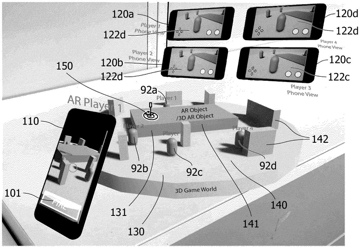
Turning now toFIGS.11and12, an example of an asymmetric digital game experience with one AR-enabled primary device (AR Player 1) and four VR-enabled devices (Player 1-4) meeting in a common multiplayer session in a 3D game world is briefly described.
FIG.11shows schematically a primary user device110capturing a real world scene130comprising a toy model131of e.g. a building, and a user-manipulable object150. The real-world scene may be set on a table in a room where a primary user operating the primary user device110may be located. The primary user device may be operated to join a multiplayer session140, here represented by a three-dimensional game world defining a virtual scene corresponding to the real world scene. The primary user device may show a primary view of the real world scene130augmented with computer-generated content to provide an AR-experience. The primary view is shown as seen from a primary view point, which may be controlled e.g. by moving the primary user device110with respect to the real world scene130, wherein the computer-generated AR-content is tracked and presented on a display screen of the primary user device110accordingly. In addition to a computer-generated virtual representation141of the toy model131, the multiplayer session140comprises further computer-generated virtual objects142that may be thematically linked to the toy model131and its virtual representation141. For example, if the toy model131is a pirate ship, the virtual scene140may be set on a deserted island surrounded by dangerous reefs, and the additional virtual objects142may include palm trees, primitive huts, and a treasure cave. Furthermore,FIG.11shows secondary user devices120a-d, which may or may not be at the same location as the real world scene and the primary user device. The secondary user devices120a-dmay be operated to join the same multiplayer session140as the primary user device110. The secondary user devices120a-dmay access the multiplayer session140through a local or remote link depending on the location and the actual implementation of the multiplayer session140as discussed elsewhere herein. The secondary user devices120a-dcan then on a display thereof show a respective secondary view122a-dof the virtual three-dimensional game world including the virtual representation141of the toy model131and any of the additional virtual objects142, according to the respective secondary view point of the secondary user device120a-d. The secondary view point may be the point of view of a playable character associated with a given secondary user device120a-d. The playable character may be controlled by the secondary user using input controls123, which may be touch sensitive input areas on a graphical user interface of the secondary user device120a-d, e.g. configured with buttons and/or a joy-stick control functionality.
In the above-mentioned pirate setting, the primary player (or a team of primary players not shown here) may play treasure hunter (or a group of treasure hunters), and the secondary players may be left-behind pirates trying to defend the treasure. User-manipulable objects may then be manipulated to modify the flow of the game e.g. changing the weather by a random spin of a color wheel, releasing wild animals, or for conjuring spirits of cursed pirates.
In another example, the toy model131may be a model of a haunted house fairground attraction, which then may be set in a virtual fairground scene equipped with additional objects142, such as further fairground attractions like a merry-go-rounds, a roller coaster, a fortune teller's tent, or an ice cream and popcorn sales cart. The fairground may be haunted by ghosts played by secondary users using secondary user devices120a-d. The ghosts may move around haunting different attractions as controlled by means of the user inputs123on the secondary user devices120a-d. The ghosts may be of different kinds, each kind being associated with a pre-determined color. A primary user (or a team of primary players not shown here), may have the task to hunt the ghosts, but may only be able to see the ghosts of one color at a time, according to a current color setting. The current color setting may be determined by means of a user-manipulable object150, such as the above-mentioned color wheel, which may be controlled by the primary user. Moving around the ghosts may also hide behind or under objects141,142in the virtual scene140. When a ghost comes into sight, the ghost hunter may catch or eliminate the ghost by aiming with the AR-enabled primary user device at the virtual representation of the secondary player92a-d, here a ghost of a given color, and pressing at the FIRE button. Generally, the real world scene may also comprise a plurality of user-manipulable objects distributed through the scene and with different functionalities and effect on the game. For example, a user-manipulable object (not shown) may have a hatch concealing a symbol or code characterizing a detectable state. By opening the hatch and detecting the revealed symbol or code with the primary user device110, a side-kick helping the ghost hunter to seek the hidden ghosts may be activated. At the secondary device a change in the current color setting may be indicated by a change in color of an element of the avatar of the primary player, and may also activate portals for the ghosts of the current color to escape into another color. In a similar manner, activating the side kick may result in a visual, audible, tactile, and/or other user-perceptible output to be produced on the secondary devices indicating the detected state (or change in state) and/or modifying thereby the flow of the multiplayer game session.
Very briefly,FIG.12merely illustrates an example of a game world including various obstacles allowing a secondary player to hide from a primary player in e.g. a hide-and-seek type of game, such as the above-mentioned specific implementation of a hide-and-seek concept in a hunter's game. The obstacles may include any of the computer-generated objects141,142in the virtual scene140.
As mentioned above, the different aspects of the present invention can be implemented in different ways including the toy system described in respect of the various embodiments of the aspects described above and in the following. Further aspects of the present invention can e.g. be implemented as corresponding methods, apparatus, and products. Each aspect, yields one or more of the benefits and advantages described in connection with at least one of the aspects described above, and each aspect having one or more preferred embodiments corresponding to the preferred embodiments described in connection with at least one of the aspects described above and in the following and/or disclosed in the dependant claims. Furthermore, it will be appreciated that embodiments described in connection with one of the aspects described herein may equally be applied to the other aspects.
In particular, a computer-implemented method is provided for generating an asymmetric multiplayer play experience, the process comprising:capturing a sequence of images of a real world scene using a primary user device, the real-world scene including at least one toy with a user-manipulable object;operating the primary user device and at least one secondary user device to join in a common multiplayer digital game session;in the multiplayer game session, providing a virtual representation corresponding to the real world scene;processing the captured images to detect at least a first predetermined state of the user-manipulable object within the real-world scene;providing information on the first predetermined state to the multiplayer session;responsive to the information on the detected predetermined state, generating and rendering computer-generated user-perceptible output associated with the detected pre-determined state at the at least one secondary user device.
Furthermore, a data processing system is provided that is configured, e.g. by suitable program code stored on the data processing system, to perform the steps of one or more of the computer-implemented methods explicitly described or implicitly disclosed herein.
Yet further, a computer program product is provided comprising program code adapted to cause, when executed on a data processing system, a data processing system to perform the steps of one or more of the computer-implemented methods explicitly described or implicitly disclosed herein.
The computer program product may be provided as a computer-readable medium, such as a CD-ROM, DVD, optical disc, memory card, flash memory, magnetic storage device, floppy disk, hard disk, etc. In other embodiments, a computer program product may be provided as a downloadable software package, an App, or the like, e.g. on a web server for download over the internet or other computer or communication network. In particular, an embodiment of a toy construction set may include toy construction elements, and installation instructions for installing a computer program product on a suitable data processing system.
In the claims enumerating several means, several of these means can be embodied by one and the same element, component or item of hardware. The mere fact that certain measures are recited in mutually different dependent claims or described in different embodiments does not indicate that a combination of these measures cannot be used to advantage.
It should be emphasized that the term “comprises/comprising” when used in this specification is taken to specify the presence of stated features, elements, steps or components but does not preclude the presence or addition of one or more other features, elements, steps, components or groups thereof.
Claims
- A method of controlling an asymmetric multiplayer game system comprising the steps of: operating a primary user device and a secondary user device in a common multiplayer game session;capturing, with the primary user device within the common multiplayer game session, a sequence of images of a real world scene including a user manipulable object having a plurality of user-selectable states;modifying, within the common multiplayer game session, a user-selected state of the user-manipulable object;detecting, with the primary user device within the common multiplayer game session, a change in the user-selected state of the user-manipulable object in the captured sequence of images;sharing, within the common multiplayer game session, information indicative of the detected change in the user-selected state;providing, within the common multiplayer game session, secondary programmed instructions responsive to the detected change in the user-selected state;and executing, within the common multiplayer game session, the secondary programmed instructions at a secondary user device.
- A method as recited in claim 1, wherein the primary user device comprises a processing unit, a user interface including a display, and an image capturing device, the primary user device being adapted to detect the change in the user-selected state of the user-manipulable object by providing the captured sequence of images to a computer vision process configured to recognize user-selected states of the user-manipulable object, comparing a currently recognized user-selected state with a stored previous user-selected state, and determining that a change has occurred if a discrepancy is observed.
- A method as recited in claim 2, wherein the computer vision process includes a feature recognition process and an object recognition process.
- A method as recited in claim 1, wherein the primary user device is configured to generate and render user-perceptible output prompting the primary user of the primary user device to manipulate the real world scene by setting a state of the user-manipulable object.
- A method as recited in claim 4, wherein the user-perceptible output includes: prompting the primary user to set the user-manipulable object to a pre-determined user-selected state;and providing guidance to point a capturing device of the primary user device towards a location of the user-manipulable object.
- A method as recited in claim 1, wherein the secondary programmed instructions include one or more of: game code;and instructions for generating user-perceptible output.
- A method as recited in claim 1, further comprising the step of grouping a plurality of primary and secondary user devices as teams in the common multiplayer game session.
- A method as recited in claim 1, wherein the primary user device and the secondary user device are selected from the group consisting of: augmented reality enabled (AR) devices;and virtual reality enabled (VR) devices.
- A method as recited in claim 1, wherein the common multiplayer game session is implemented on components selected from the group consisting of the primary user device, the secondary user device, a networked processing device, and a cloud computing environment.
- A method of controlling an asymmetric multiplayer game environment for multiplayer game session processing, the method comprising the steps of: receiving one or more primary user devices and one or more secondary user devices in a common multiplayer game session;receiving, within the common multiplayer game session, from a primary one of the user devices a sequence of images of a real world scene including a user manipulable object, the user manipulable object having a plurality of user-selectable states;detecting, within the common multiplayer game session, in the sequence of images a change in a user-selected state of the user-manipulable object;sharing, within the common multiplayer game session, information indicative of the change in the user-selected state within the common multiplayer game session;responsive to the change in the user-selected state, providing, within the common multiplayer game session, secondary programmed instructions;and causing, within the common multiplayer game session, the secondary programmed instructions to be executed at one of the one or more secondary user devices.
- A method as recited in claim 10, wherein the one or more primary user devices and the one or more secondary user devices are selected from the group consisting of: augmented reality enabled (AR) devices;and virtual reality enabled (VR) devices.
- A method as recited in claim 10, further comprising the step of grouping a plurality of primary and secondary user devices as teams in the common multiplayer game session.
- A method of controlling a multiplayer game environment for an asymmetric multiplayer game session processing, the method comprising the steps of: establishing communication between a plurality of user devices in a common multiplayer game session;receiving, within the common multiplayer game session, from a primary one of the user devices a sequence of images of a real world scene including a user manipulable object, the user manipulable object having a plurality of user-selectable states;detecting, within the common multiplayer game session, in the sequence of images a change in a user-selected state of the user-manipulable object;providing, within the common multiplayer game session, programmed instructions to the plurality of user devices based on the change in the user-selected state;and executing, within the common multiplayer game session, the secondary programmed instructions.
Disclaimer: Data collected from the USPTO and may be malformed, incomplete, and/or otherwise inaccurate.