U.S. Pat. No. 11,951,383
CONTROLLING GAME PROCESSING USING DETERMINED ROTATIONAL DIRECTION IN COMBINATION WITH DETERMINED UP/DOWN DIRECTION
AssigneeNintendo Co Ltd
Issue DateSeptember 9, 2022
Illustrative Figure
Abstract
Using output of an inertial sensor, whether an operation device is in a swing state of being swung is determined. Whether the operation device is rotated in a first direction about a predetermined axis of the inertial sensor or a second direction opposite to the first direction, is determined. Whether the operation device is swung in an upward direction or a downward direction is determined. First processing is executed in at least either a case where the operation device is rotated in the first direction about the predetermined axis or a case where the operation device is swung in the upward direction, during the swing state. Second processing is executed in at least either a case where the operation device is rotated in the second direction about the predetermined axis or a case where the operation device is swung in the downward direction, during the swing state.
Description
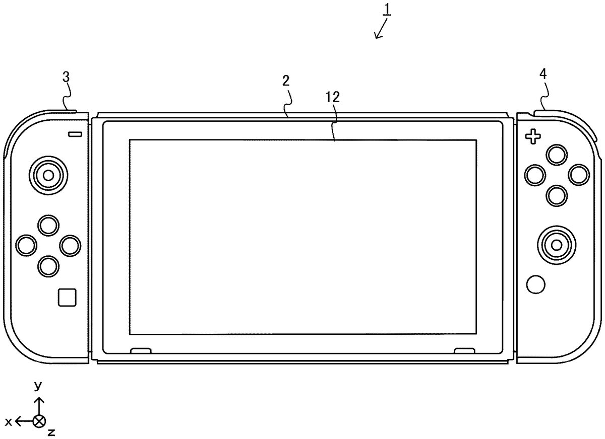
DETAILED DESCRIPTION OF NON-LIMITING EXAMPLE EMBODIMENTS Hereinafter, one exemplary embodiment will be described. A game system according to an example of the exemplary embodiment will be described below. An example of a game system1according to the exemplary embodiment includes a main body apparatus (an information processing apparatus, which functions as a game apparatus main body in the exemplary embodiment)2, a left controller3, and a right controller4. Each of the left controller3and the right controller4is attachable to and detachable from the main body apparatus2. That is, the game system1can be used as a unified apparatus obtained by attaching each of the left controller3and the right controller4to the main body apparatus2. Further, in the game system1, the main body apparatus2, the left controller3, and the right controller4can also be used as separate bodies (seeFIG.2). Hereinafter, first, the hardware configuration of the game system1according to the exemplary embodiment will be described, and then, the control of the game system1according to the exemplary embodiment will be described. FIG.1shows an example of the state where the left controller3and the right controller4are attached to the main body apparatus2. As shown inFIG.1, each of the left controller3and the right controller4is attached to and unified with the main body apparatus2. The main body apparatus2is an apparatus for performing various processes (e.g., game processing) in the game system1. The main body apparatus2includes a display12. Each of the left controller3and the right controller4is an apparatus including operation sections with which a user provides inputs. FIG.2shows an example of the state where each of the left controller3and the right controller4is detached from the main body apparatus2. As shown inFIGS.1and2, the left controller3and the right controller4are attachable to and detachable from the main body apparatus2. Hereinafter, the left controller3and the right controller4may be collectively referred to as “controller”. FIG.3is six orthogonal views ...
DETAILED DESCRIPTION OF NON-LIMITING EXAMPLE EMBODIMENTS
Hereinafter, one exemplary embodiment will be described.
A game system according to an example of the exemplary embodiment will be described below. An example of a game system1according to the exemplary embodiment includes a main body apparatus (an information processing apparatus, which functions as a game apparatus main body in the exemplary embodiment)2, a left controller3, and a right controller4. Each of the left controller3and the right controller4is attachable to and detachable from the main body apparatus2. That is, the game system1can be used as a unified apparatus obtained by attaching each of the left controller3and the right controller4to the main body apparatus2. Further, in the game system1, the main body apparatus2, the left controller3, and the right controller4can also be used as separate bodies (seeFIG.2). Hereinafter, first, the hardware configuration of the game system1according to the exemplary embodiment will be described, and then, the control of the game system1according to the exemplary embodiment will be described.
FIG.1shows an example of the state where the left controller3and the right controller4are attached to the main body apparatus2. As shown inFIG.1, each of the left controller3and the right controller4is attached to and unified with the main body apparatus2. The main body apparatus2is an apparatus for performing various processes (e.g., game processing) in the game system1. The main body apparatus2includes a display12. Each of the left controller3and the right controller4is an apparatus including operation sections with which a user provides inputs.
FIG.2shows an example of the state where each of the left controller3and the right controller4is detached from the main body apparatus2. As shown inFIGS.1and2, the left controller3and the right controller4are attachable to and detachable from the main body apparatus2. Hereinafter, the left controller3and the right controller4may be collectively referred to as “controller”.
FIG.3is six orthogonal views showing an example of the main body apparatus2. As shown inFIG.3, the main body apparatus2includes an approximately plate-shaped housing11. In the exemplary embodiment, a main surface (in other words, a surface on a front side, i.e., a surface on which the display12is provided) of the housing11has a substantially rectangular shape.
The shape and the size of the housing11are discretionary. As an example, the housing11may be of a portable size. Further, the main body apparatus2alone or the unified apparatus obtained by attaching the left controller3and the right controller4to the main body apparatus2may function as a mobile apparatus. The main body apparatus2or the unified apparatus may function as a handheld apparatus or a portable apparatus.
As shown inFIG.3, the main body apparatus2includes the display12, which is provided on the main surface of the housing11. The display12displays an image generated by the main body apparatus2. In the exemplary embodiment, the display12is a liquid crystal display device (LCD). The display12, however, may be a display device of any type.
The main body apparatus2includes a touch panel13on the screen of the display12. In the exemplary embodiment, the touch panel13is of a type capable of receiving a multi-touch input (e.g., electrical capacitance type). However, the touch panel13may be of any type, and may be, for example, of a type capable of receiving a single-touch input (e.g., resistive film type).
The main body apparatus2includes speakers (i.e., speakers88shown inFIG.6) within the housing11. As shown inFIG.3, speaker holes11aand11bare formed in the main surface of the housing11. Then, sounds outputted from the speakers88are outputted through the speaker holes11aand11b.
Further, the main body apparatus2includes a left terminal17, which is a terminal for the main body apparatus2to perform wired communication with the left controller3, and a right terminal21, which is a terminal for the main body apparatus2to perform wired communication with the right controller4.
As shown inFIG.3, the main body apparatus2includes a slot23. The slot23is provided at an upper side surface of the housing11. The slot23is so shaped as to allow a predetermined type of storage medium to be attached to the slot23. The predetermined type of storage medium is, for example, a dedicated storage medium (e.g., a dedicated memory card) for the game system1and an information processing apparatus of the same type as the game system1. The predetermined type of storage medium is used to store, for example, data (e.g., saved data of an application or the like) used by the main body apparatus2and/or a program (e.g., a program for an application or the like) executed by the main body apparatus2. Further, the main body apparatus2includes a power button28.
The main body apparatus2includes a lower terminal27. The lower terminal27is a terminal for the main body apparatus2to communicate with a cradle. In the exemplary embodiment, the lower terminal27is a USB connector (more specifically, a female connector). Further, when the unified apparatus or the main body apparatus2alone is mounted on the cradle, the game system1can display on a stationary monitor an image generated by and outputted from the main body apparatus2. Further, in the exemplary embodiment, the cradle has the function of charging the unified apparatus or the main body apparatus2alone mounted on the cradle. Further, the cradle has the function of a hub device (specifically, a USB hub).
FIG.4is six orthogonal views showing an example of the left controller3. As shown inFIG.4, the left controller3includes a housing31. In the exemplary embodiment, the housing31has a vertically long shape, i.e., is shaped to be long in an up-down direction shown inFIG.4(i.e., a z-axis direction shown inFIG.4). In the state where the left controller3is detached from the main body apparatus2, the left controller3can also be held in the orientation in which the left controller3is vertically long. The housing31has such a shape and a size that when held in the orientation in which the housing31is vertically long, the housing31can be held with one hand, particularly, the left hand. Further, the left controller3can also be held in the orientation in which the left controller3is horizontally long. When held in the orientation in which the left controller3is horizontally long, the left controller3may be held with both hands.
The left controller3includes a left analog stick (hereinafter, referred to as a “left stick”)32as an example of a direction input device. As shown inFIG.4, the left stick32is provided on a main surface of the housing31. The left stick32can be used as a direction input section with which a direction can be inputted. The user tilts the left stick32and thereby can input a direction corresponding to the direction of the tilt (and input a magnitude corresponding to the angle of the tilt). The left controller3may include a directional pad, a slide stick that allows a slide input, or the like as the direction input section, instead of the analog stick. Further, in the exemplary embodiment, it is possible to provide an input by pressing the left stick32.
The left controller3includes various operation buttons. The left controller3includes four operation buttons33to36(specifically, a right direction button33, a down direction button34, an up direction button35, and a left direction button36) on the main surface of the housing31. Further, the left controller3includes a record button37and a “—” (minus) button47. The left controller3includes a first L-button38and a ZL-button39in an upper left portion of a side surface of the housing31. Further, the left controller3includes a second L-button43and a second R-button44, on the side surface of the housing31on which the left controller3is attached to the main body apparatus2. These operation buttons are used to give instructions depending on various programs (e.g., an OS program and an application program) executed by the main body apparatus2.
Further, the left controller3includes a terminal42for the left controller3to perform wired communication with the main body apparatus2.
FIG.5is six orthogonal views showing an example of the right controller4. As shown inFIG.5, the right controller4includes a housing51. In the exemplary embodiment, the housing51has a vertically long shape, i.e., is shaped to be long in the up-down direction shown inFIG.5(i.e., the z-axis direction shown inFIG.5). In the state where the right controller4is detached from the main body apparatus2, the right controller4can also be held in the orientation in which the right controller4is vertically long. The housing51has such a shape and a size that when held in the orientation in which the housing51is vertically long, the housing51can be held with one hand, particularly the right hand. Further, the right controller4can also be held in the orientation in which the right controller4is horizontally long. When held in the orientation in which the right controller4is horizontally long, the right controller4may be held with both hands.
Similarly to the left controller3, the right controller4includes a right analog stick (hereinafter, referred to as a “right stick”)52as a direction input section. In the exemplary embodiment, the right stick52has the same configuration as that of the left stick32of the left controller3. Further, the right controller4may include a directional pad, a slide stick that allows a slide input, or the like, instead of the analog stick. Further, similarly to the left controller3, the right controller4includes four operation buttons53to56(specifically, an A-button53, a B-button54, an X-button55, and a Y-button56) on a main surface of the housing51. Further, the right controller4includes a “+” (plus) button57and a home button58. Further, the right controller4includes a first R-button60and a ZR-button61in an upper right portion of a side surface of the housing51. Further, similarly to the left controller3, the right controller4includes a second L-button65and a second R-button66.
Further, the right controller4includes a terminal64for the right controller4to perform wired communication with the main body apparatus2.
FIG.6is a block diagram showing an example of the internal configuration of the main body apparatus2. The main body apparatus2includes components81to91,97, and98shown inFIG.6in addition to the components shown inFIG.3. Some of the components81to91,97, and98may be mounted as electronic components on an electronic circuit board and housed in the housing11.
The main body apparatus2includes a processor81. The processor81is an information processing section for executing various types of information processing to be executed by the main body apparatus2. For example, the processor81may be composed only of a CPU (Central Processing Unit), or may be composed of a SoC (System-on-a-chip) having a plurality of functions such as a CPU function and a GPU (Graphics Processing Unit) function. The processor81executes an information processing program (e.g., a game program) stored in a storage section (specifically, an internal storage medium such as a flash memory84, an external storage medium attached to the slot23, or the like), thereby performing the various types of information processing.
The main body apparatus2includes the flash memory84and a DRAM (Dynamic Random Access Memory)85as examples of internal storage media built into the main body apparatus2. The flash memory84and the DRAM85are connected to the processor81. The flash memory84is a memory mainly used to store various data (or programs) to be saved in the main body apparatus2. The DRAM85is a memory used to temporarily store various data used for information processing.
The main body apparatus2includes a slot interface (hereinafter, abbreviated as “I/F”)91. The slot I/F91is connected to the processor81. The slot I/F91is connected to the slot23, and in accordance with an instruction from the processor81, reads and writes data from and to the predetermined type of storage medium (e.g., a dedicated memory card) attached to the slot23.
The processor81appropriately reads and writes data from and to the flash memory84, the DRAM85, and each of the above storage media, thereby performing the above information processing.
The main body apparatus2includes a network communication section82. The network communication section82is connected to the processor81. The network communication section82communicates (specifically, through wireless communication) with an external apparatus via a network. In the exemplary embodiment, as a first communication form, the network communication section82connects to a wireless LAN and communicates with an external apparatus, using a method compliant with the Wi-Fi standard. Further, as a second communication form, the network communication section82wirelessly communicates with another main body apparatus2of the same type, using a predetermined method for communication (e.g., communication based on a unique protocol or infrared light communication). The wireless communication in the above second communication form achieves the function of enabling so-called “local communication” in which the main body apparatus2can wirelessly communicate with another main body apparatus2placed in a closed local network area, and the plurality of main body apparatuses2directly communicate with each other to transmit and receive data.
The main body apparatus2includes a controller communication section83. The controller communication section83is connected to the processor81. The controller communication section83wirelessly communicates with the left controller3and/or the right controller4. The communication method between the main body apparatus2, and the left controller3and the right controller4, is discretionary. In the exemplary embodiment, the controller communication section83performs communication compliant with the Bluetooth (registered trademark) standard with the left controller3and with the right controller4.
The processor81is connected to the left terminal17, the right terminal21, and the lower terminal27. When performing wired communication with the left controller3, the processor81transmits data to the left controller3via the left terminal17and also receives operation data from the left controller3via the left terminal17. Further, when performing wired communication with the right controller4, the processor81transmits data to the right controller4via the right terminal21and also receives operation data from the right controller4via the right terminal21. Further, when communicating with the cradle, the processor81transmits data to the cradle via the lower terminal27. As described above, in the exemplary embodiment, the main body apparatus2can perform both wired communication and wireless communication with each of the left controller3and the right controller4. Further, when the unified apparatus obtained by attaching the left controller3and the right controller4to the main body apparatus2or the main body apparatus2alone is attached to the cradle, the main body apparatus2can output data (e.g., image data or sound data) to the stationary monitor or the like via the cradle.
Here, the main body apparatus2can communicate with a plurality of left controllers3simultaneously (in other words, in parallel). Further, the main body apparatus2can communicate with a plurality of right controllers4simultaneously (in other words, in parallel). Thus, a plurality of users can simultaneously provide inputs to the main body apparatus2, each using a set of the left controller3and the right controller4. As an example, a first user can provide an input to the main body apparatus2using a first set of the left controller3and the right controller4, and simultaneously, a second user can provide an input to the main body apparatus2using a second set of the left controller3and the right controller4.
The main body apparatus2includes a touch panel controller86, which is a circuit for controlling the touch panel13. The touch panel controller86is connected between the touch panel13and the processor81. On the basis of a signal from the touch panel13, the touch panel controller86generates data indicating the position at which a touch input has been performed, for example, and outputs the data to the processor81.
Further, the display12is connected to the processor81. The processor81displays a generated image (e.g., an image generated by executing the above information processing) and/or an externally acquired image on the display12.
The main body apparatus2includes a codec circuit87and speakers (specifically, a left speaker and a right speaker)88. The codec circuit87is connected to the speakers88and a sound input/output terminal25and also connected to the processor81. The codec circuit87is a circuit for controlling the input and output of sound data to and from the speakers88and the sound input/output terminal25.
The main body apparatus2includes a power control section97and a battery98. The power control section97is connected to the battery98and the processor81. Further, although not shown inFIG.6, the power control section97is connected to components of the main body apparatus2(specifically, components that receive power supplied from the battery98, the left terminal17, and the right terminal21). On the basis of a command from the processor81, the power control section97controls the supply of power from the battery98to the above components.
Further, the battery98is connected to the lower terminal27. When an external charging device (e.g., the cradle) is connected to the lower terminal27and power is supplied to the main body apparatus2via the lower terminal27, the battery98is charged with the supplied power.
FIG.7is a block diagram showing examples of the internal configurations of the main body apparatus2, the left controller3, and the right controller4. The details of the internal configuration of the main body apparatus2are shown inFIG.6and therefore are omitted inFIG.7.
The left controller3includes a communication control section101, which communicates with the main body apparatus2. As shown inFIG.7, the communication control section101is connected to components including the terminal42. In the exemplary embodiment, the communication control section101can communicate with the main body apparatus2through both wired communication via the terminal42and wireless communication not via the terminal42. The communication control section101controls the method for communication performed by the left controller3with the main body apparatus2. That is, when the left controller3is attached to the main body apparatus2, the communication control section101communicates with the main body apparatus2via the terminal42. Further, when the left controller3is detached from the main body apparatus2, the communication control section101wirelessly communicates with the main body apparatus2(specifically, the controller communication section83). The wireless communication between the communication control section101and the controller communication section83is performed in accordance with the Bluetooth (registered trademark) standard, for example.
Further, the left controller3includes a memory102such as a flash memory. The communication control section101includes, for example, a microcomputer (or a microprocessor) and executes firmware stored in the memory102, thereby performing various processes.
The left controller3includes buttons103(specifically, the buttons33to39,43,44, and47). Further, the left controller3includes the left stick32. Each of the buttons103and the left stick32outputs information regarding an operation performed on itself to the communication control section101repeatedly at appropriate timings.
The left controller3includes inertial sensors. Specifically, the left controller3includes an acceleration sensor104. Further, the left controller3includes an angular velocity sensor105. In the exemplary embodiment, the acceleration sensor104detects the magnitudes of accelerations along predetermined three axial (e.g., x, y, z axes shown inFIG.4) directions. The acceleration sensor104may detect an acceleration along one axial direction or accelerations along two axial directions. In the exemplary embodiment, the angular velocity sensor105detects angular velocities about predetermined three axes (e.g., the x, y, z axes shown inFIG.4). The angular velocity sensor105may detect an angular velocity about one axis or angular velocities about two axes. Each of the acceleration sensor104and the angular velocity sensor105is connected to the communication control section101. Then, the detection results of the acceleration sensor104and the angular velocity sensor105are outputted to the communication control section101repeatedly at appropriate timings.
The communication control section101acquires information regarding an input (specifically, information regarding an operation or the detection result of the sensor) from each of input sections (specifically, the buttons103, the left stick32, and the sensors104and105). The communication control section101transmits operation data including the acquired information (or information obtained by performing predetermined processing on the acquired information) to the main body apparatus2. The operation data is transmitted repeatedly, once every predetermined time. The interval at which the information regarding an input is transmitted from each of the input sections to the main body apparatus2may or may not be the same.
The above operation data is transmitted to the main body apparatus2, whereby the main body apparatus2can obtain inputs provided to the left controller3. That is, the main body apparatus2can determine operations on the buttons103and the left stick32on the basis of the operation data. Further, the main body apparatus2can calculate information regarding the motion and/or the orientation of the left controller3on the basis of the operation data (specifically, the detection results of the acceleration sensor104and the angular velocity sensor105).
The left controller3includes a power supply section108. In the exemplary embodiment, the power supply section108includes a battery and a power control circuit. Although not shown inFIG.7, the power control circuit is connected to the battery and also connected to components of the left controller3(specifically, components that receive power supplied from the battery).
As shown inFIG.7, the right controller4includes a communication control section111, which communicates with the main body apparatus2. Further, the right controller4includes a memory112, which is connected to the communication control section111. The communication control section111is connected to components including the terminal64. The communication control section111and the memory112have functions similar to those of the communication control section101and the memory102, respectively, of the left controller3. Thus, the communication control section111can communicate with the main body apparatus2through both wired communication via the terminal64and wireless communication not via the terminal64(specifically, communication compliant with the Bluetooth (registered trademark) standard). The communication control section111controls the method for communication performed by the right controller4with the main body apparatus2.
The right controller4includes input sections similar to the input sections of the left controller3. Specifically, the right controller4includes buttons113, the right stick52, and inertial sensors (an acceleration sensor114and an angular velocity sensor115). These input sections have functions similar to those of the input sections of the left controller3and operate similarly to the input sections of the left controller3.
The right controller4includes a power supply section118. The power supply section118has a function similar to that of the power supply section108of the left controller3and operates similarly to the power supply section108.
[Outline of Game Processing in Exemplary Embodiment]
Next, the outline of operation of the game processing executed by the game system1according to the exemplary embodiment will be described. As described above, in the game system1, the main body apparatus2is configured such that each of the left controller3and the right controller4is attachable thereto and detachable therefrom. In a case of playing the game with the left controller3and the right controller4attached to the main body apparatus2, a game image is outputted to the display12. In a case where the main body apparatus2alone with the left controller3and the right controller4detached therefrom is mounted on the cradle, the main body apparatus2can output a game image to a stationary monitor or the like via the cradle. In the exemplary embodiment, the case of playing the game in the latter manner will be described as an example. Specifically, the main body apparatus2alone with the left controller3and the right controller4detached therefrom is mounted on the cradle, and the main body apparatus2outputs a game image and the like to a stationary monitor or the like via the cradle. Here, it is assumed that a right-handed player plays the game with the right controller4held by the right hand. The left controller3is not used in the exemplary embodiment. However, for example, if the player is left-handed, the processing as described below may be performed using the left controller3instead of the right controller4.
[Assumed Game]
The game assumed in the exemplary embodiment is a tennis game for players to compete in a virtual three-dimensional space. In the exemplary embodiment, as an example, a case of competing against a CPU character in a singles match will be described. As a matter of course, a player-versus-player mode in which another player operates an opponent is also applicable. In a case of the player-versus-player mode, two players may perform competitive play using one game apparatus, or may perform communication competition play by connecting two game apparatuses via a network. Instead of a singles match, a doubles match may be performed.
FIG.8shows an example of a game image of the tennis game according to the exemplary embodiment. The game image shown inFIG.8is an image obtained by a virtual camera imaging a three-dimensional virtual space (virtual tennis court). In the game image (in virtual tennis court), two character objects are displayed. On the near-side court (own-side court) of the virtual tennis court, a player character object (hereinafter, referred to as player character)201which is a player's operation target is placed. On the far-side court (opponent-side court) over the net, a character object (hereinafter, referred to as opponent character)202which is an opponent is placed. Each character object holds a tennis racket object (hereinafter, simply referred to as racket) with the right hand. Besides, in the game image, a tennis ball object (hereinafter, simply referred to as ball)203which is a moving object is also displayed.
Basic specifications and operation method of the tennis game according to the exemplary embodiment will be described. First, in this tennis game, the player swings the right controller4resembling a racket, whereby the player can cause the player character201to swing the racket in a direction corresponding to the swing direction. In the exemplary embodiment, it is assumed that the right controller4is swung while held in such a way that the surface having operation buttons resembles a racket face (surface for hitting a ball), as an example. Hereinafter, a motion of the player character201swinging the racket is referred to as racket swing motion. In this tennis game, movement of the player character201is automatically controlled. That is, in accordance with the movement trajectory (movement direction) of the ball203, the player character201automatically moves in the own-side court toward such a position where the player character201can hit the ball203back (hereinafter, such movement is referred to as automatic movement). Therefore, in this game, the player only has to concentrate on an operation of swinging the right controller4in accordance with a timing when the ball203has come, without considering a movement operation.
In actual tennis, there is known a technique for imparting rotation to a tennis ball when hitting the ball back, like so-called topspin and backspin. In the processing according to the exemplary embodiment, such an element of imparting rotation to a tennis ball is introduced into an operation in the tennis game described above.
Specifically, in the exemplary embodiment, the following processing is performed. First, the twist degree of the wrist of a hand holding the right controller4is calculated. Further, whether the way of swinging the right controller4is swing-up or swing-down down is determined. Then, on the basis of these two elements, the movement of the ball203is controlled in such a way that topspin or backspin is imparted.
FIG.9toFIG.11show examples of the trajectory (hereinafter, referred to as ball trajectory) of movement of the ball203under the above movement control.FIG.9shows an example of a ball trajectory when the ball203is not imparted with rotation,FIG.10shows an example of a ball trajectory when topspin is imparted, andFIG.11shows an example of a ball trajectory when backspin is imparted.FIG.9toFIG.11all show a case where the ball203is hit toward the z-axis positive direction. As shown inFIG.10, the ball trajectory when topspin is imparted becomes such a ball trajectory that the ball203rises higher than inFIG.9and bounces farther toward the forward direction of the (z-axis) movement direction than in a case where the ball203is not imparted with rotation. On the other hand, in a case of backspin, as shown inFIG.11, the ball trajectory becomes lower than in the case where the ball203is not imparted with rotation, and the height and the distance when the ball203bounces are smaller than in the case where the ball203is not imparted with rotation.
A determination method for the above ways of swing will be described more specifically. In the exemplary embodiment, twist of a wrist is determined on the basis of the degree of rotation (rotation amount) about the z axis of the right controller4.FIG.12shows a plan view of the right controller4andFIG.13shows a back view thereof. As shown inFIG.12, using an orientation in which the surface having the right stick52faces directly upward as a reference orientation, whether the rotation is rightward or leftward is determined. In general, in a case of imparting topspin, swing is performed in such a way as to impart rotation in the forward direction with respect to the direction in which the hit-back ball moves. In this case, about the z axis, an operation of swinging with the wrist twisted so as to rotate leftward is assumed (for a right-handed player). On the other hand, in a case of backspin, in contrast to the above, swing is performed in such a way as to impart rotation in the reverse direction with respect to the direction in which the hit-back ball moves. In this case, about the z axis, an operation of swinging with the wrist twisted so as to rotate rightward is assumed. Accordingly, in the exemplary embodiment, orientation change in the right controller4about the z axis during the swing operation is observed to determine whether the rotation is performed rightward or leftward, and the result is used for determination as to an operation of imparting topspin or backspin to the ball203.
In addition, focusing on the actual way of swinging the racket when imparting topspin/backspin, in general, swing is performed in such a way as to swing up in the upward direction in the real space in a case of imparting topspin, and swing is performed in such a way as to swing down in the downward direction in the real space in a case of imparting backspin. Accordingly, in the exemplary embodiment, in addition to observation of rotation about the z axis described above, whether a swing action (swing direction) during the swing operation is a swing-up action (upward swing direction) or a swing-down action (downward swing direction) is also determined. Then, the result thereof is used for determination as to an operation for topspin/backspin. In the exemplary embodiment, the swing-up/swing-down determination is performed on the basis of the change amount of the orientation of the right controller4during the swing operation, and the details thereof will be described later.
FIG.14shows an example of orientation change in the right controller4when topspin is imparted, andFIG.15shows an example of orientation change in the right controller4when backspin is imparted.FIG.14andFIG.15both show views of the right controller4as seen from the front side (side where the first R-button60and the ZR-button61can be seen). In a case of imparting topspin, a swing action of swinging up while rotating the controller leftward about the z axis is performed. In a case of imparting backspin, a swing action of swinging up while rotating the controller rightward about the z axis is performed.
In the exemplary embodiment, as described above, on the basis of parameters corresponding to two elements that are the degree of rotation (degree of twist of wrist) about the z axis and the up/down direction of the swing action (swing up/swing down), whether an operation of imparting topspin to the ball203(hereinafter, referred to as topspin operation) or an operation of imparting backspin to the ball203(hereinafter, referred to as backspin operation) has been performed is determined. In addition, in the exemplary embodiment, in a case where the parameters do not satisfy a predetermined condition, it is determined that an operation of hitting a ball by a so-called flat shot has been performed. In this case, movement control is performed so that the ball203moves with no rotation imparted. That is, the exemplary embodiment provides a player with such operability that allows three types of shots, i.e., a topspin shot, a backspin shot, and a flat shot, to be selectively used on the basis of the above parameters. In other words, processing for moving the ball203is performed such that the ball trajectory thereof, which would be a flat shot trajectory (seeFIG.9) if a shot is made in a normal way, is imparted with a first change (seeFIG.10) if a topspin operation is performed, or is imparted with a second change (seeFIG.11) if a backspin operation is performed.
Here, in the following description, the parameter indicating the degree of rotation about the z axis is referred to as “z-axis rotation value”. In addition, the parameter indicating the up/down direction of the swing action is referred to as “up/down swing value”. Further, a ball trajectory with topspin imparted is referred to as “topspin trajectory”, a ball trajectory with backspin imparted is referred to as “backspin trajectory”, and a ball trajectory with no rotation imparted is referred to as “flat-shot trajectory”.
[Details of Tennis Game Processing in Exemplary Embodiment]
Next, with reference toFIG.16toFIG.23, the tennis game processing in the exemplary embodiment will be described in more detail.
[Used Data]
First, various data used in this tennis game processing will be described.FIG.16is a memory map showing an example of various data stored in the DRAM85of the main body apparatus2. The DRAM85of the main body apparatus2stores a game program301, character object data302, character action control data303, ball movement control data304, swing determination data305, a swing state flag306, a spin determination parameter307, operation data308, and the like.
The game program301is a program for executing the tennis game processing in the exemplary embodiment.
The character object data302is data regarding the outer appearances of the player character201and the opponent character202. The character object data302includes modeling data for a three-dimensional model of each character object, texture data thereof, and the like.
The character action control data303is data for controlling an action of each character. The character action control data303includes various data for controlling character actions, such as present position information of each character object, a movement target position in automatic movement control, motion data for reproducing various motions such as the aforementioned racket swing motion, and data indicating the present state of each character, e.g., whether or not each character is in a state of reproducing a motion.
The ball movement control data304is data for performing movement control of the ball203. The ball movement control data304includes data indicating the trajectory of a ball, the movement speed thereof, and the like.
The swing determination data305is data for determining whether or not a swing operation has been performed, and is data indicating a content relevant to the swing operation. Specifically, the swing determination data305is a buffer capable of storing acceleration data and/or angular velocity data obtained from the aforementioned inertial sensors over a predetermined period (e.g., several tens of frames). In the exemplary embodiment, using the swing determination data305, occurrence and finish of a swing operation as described above are detected and with what motion the swing operation has been performed is determined.
The swing state flag306is a flag indicating whether or not the right controller4is being swung at the present (swing state). When the flag is ON, the flag indicates that the right controller4is in a swing state at the present. The swing state flag306is initially set at OFF.
The spin determination parameter307is data used for determination as to whether or not an operation of imparting spin as described above has been performed.FIG.17shows an example of parameters included in the spin determination parameter307. The spin determination parameter307includes a total z-axis rotation value321and a total up/down swing value322. The total z-axis rotation value321is the sum (cumulative sum) of z-axis rotation values calculated every frame during the swing state. Similarly, the total up/down swing value322is the sum of up/down swing values calculated every frame during the swing state. In the exemplary embodiment, the z-axis rotation value is calculated as a value in a range of −256 to +256, as an example. Then, 0 indicates a state at the reference orientation, a positive value indicates leftward rotation, and a negative value indicates rightward rotation (namely, the magnitudes of rightward rotation and leftward rotation are each represented at 256 levels). The up/down swing value is also calculated as a value in a range of −256 to +256, as an example. Then, 0 indicates a state at the reference orientation, a positive value indicates a swing-up state and the magnitude of the motion thereof, and a negative value indicates a swing-down state and the magnitude of the motion thereof (namely, the magnitudes of the swing-up motion and the swing-down motion are each represented at 256 levels). Further, the spin determination parameter307includes a spin value323. The spin value323is a parameter calculated on the basis of the total z-axis rotation value321and the total up/down swing value322, and indicating the amount of rotation (magnitude of rotation) imparted to the ball203. The spin value323is calculated as a value in a range of −256 to +256, as an example. Then, a negative value indicates the amount of backspin rotation, a positive value indicates the amount of topspin rotation, and 0 indicates that there is no rotation (i.e., flat shot).
In this example, the z-axis rotation value and the up/down swing value are treated using a positive value and a negative value in combination with respect to 0 at the center. In another exemplary embodiment, the z-axis rotation values for indicating rightward rotation and leftward rotation may be each calculated as a positive value individually, and also the up/down swing values for indicating swing up and swing down may be each calculated as a positive value individually.
The operation data308is data obtained from the left controller3and the right controller4, and is data indicating the operation content of the user.FIG.18shows an example of the data structure of the operation data308. The operation data308includes at least digital button data331, right stick data332, left stick data333, right inertial sensor data334, and left inertial sensor data335. The digital button data331is data indicating press states of various buttons provided to the controller. The right stick data332is data indicating the content of operation to the right stick52. Specifically, the right stick data332includes two-dimensional data of x and y. The left stick data333is data indicating the content of operation to the left stick32. The right inertial sensor data334is data indicating detection results of inertial sensors such as the acceleration sensor114and the angular velocity sensor115of the right controller4. Specifically, the right inertial sensor data334includes acceleration data for three axes and angular velocity data for three axes. The left inertial sensor data335is data indicating detection results of inertial sensors such as the acceleration sensor104and the angular velocity sensor105of the left controller3.
Besides, various data necessary for the game processing are also generated as appropriate and stored in the DRAM85.
[Details of Processing Executed by Processor81]
Next, the details of the tennis game processing in the exemplary embodiment will be described. Here, operations for imparting topspin/backspin as described above and processing relevant thereto will be mainly described, while description of the details of other tennis game processes is omitted. Flowcharts shown below are merely examples of the processing procedure. Therefore, as long as the same result is obtained, the order of the processing steps may be changed. In addition, the values of variables and thresholds used in determination steps are also merely examples, and other values may be used as necessary.
FIG.19is a flowchart showing the details of the tennis game processing (for one match) according to the exemplary embodiment. The processing loop from step S1to step S14inFIG.19is repeatedly executed every frame.
When the tennis game processing (match) is started, first, in step S1, the processor81acquires the operation data308.
Next, in step S2, the processor81determines whether or not the swing state flag306is ON, to determine whether the present state is a swing state. As a result of the determination, if the present state is not a swing state (NO in step S2), in step S3, the processor81determines whether or not a swing state is started on the basis of the swing determination data305. A detection method for a swing state may be any method. In the exemplary embodiment, a swing state is determined on the basis of the acceleration in the z-axis direction. That is, the processor81determines whether or not the acceleration in the z-axis direction of the right controller4exceeds a predetermined threshold, on the basis of the swing determination data305. As a result, if the acceleration exceeds the predetermined threshold, the processor81determines that a swing state is started.
As a result of the determination, if a swing state is not started (NO in step S3), the process proceeds to step S10described later. On the other hand, if a swing state is started (YES in step S3), in step S4, the processor81sets the swing state flag306to ON. In addition, at this time, the processor81initializes the content of the spin determination parameter307.
Next, in step S5, the processor81acquires a detected value of the angular velocity about the z axis on the basis of the right inertial sensor data334, converts the acquired value to a value in a range of −256 to +256 as described above, and stores the converted value as the total z-axis rotation value321. Further, the processor81calculates the up/down swing value at this time, converts this value to a value in a range of −256 to +256 as described above, and stores the converted value as the total up/down swing value322. Then, the processor81proceeds to step S10described later.
Here, an example of a calculation method for the up/down swing value will be described. As the calculation method, any method may be used as long as the magnitude of swing in the up/down direction can be calculated. In the exemplary embodiment, the up/down swing value is calculated on the basis of the swing determination data305, by the following method.
(1) First, a cross product of a present vector indicating in which direction the z-axis direction of the right controller4is directed at the present, which is calculated from the present orientation of the controller, and a last orientation vector indicating in which direction the z-axis direction of the right controller4is directed 1 frame ago, which is calculated from the orientation of the controller 1 frame ago, is calculated, and a first normal vector is calculated on the basis of the cross product.
(2) Next, a two-dimensional vector is calculated by extracting only x-axis and y-axis components of the first normal vector.
(3) Next, a cross product of the present vector and the two-dimensional vector is calculated, and a second normal vector is calculated on the basis of the cross product.
(4) Whether the swing motion is a swing-up motion or a swing-down motion can be determined on the basis of whether the direction of the second normal vector is upward or downward. Therefore, on the basis of the second normal vector, a value indicating the magnitude of a swing-up/swing-down motion (change amount of orientation) is calculated as the up/down swing value. Here, the up/down swing value is calculated to be a value in a range of −256 to +256 as described above.
Regarding calculation of the first normal vector in the above calculation method, in the exemplary embodiment, the orientation of the controller 1 frame ago is used as the last orientation vector. In another exemplary embodiment, the orientation of the controller calculated from the right inertial sensor data334acquired at the last time instead of 1 frame ago may be used. For example, in a case where the interval at which the operation data308is transmitted from the controller to the main body apparatus2is smaller than the frame rate interval, a plurality of inertial sensor data can be acquired within 1 frame. Then, the orientation of the controller (last orientation vector) may be calculated on the basis of the last acquired data among the plurality of inertial sensor data.
Next, processing in a case where it is determined that the present state is a swing state (YES in step S2) as a result of the determination in step S2will be described. In this case, first, in step S6, the processor81calculates the z-axis rotation value on the basis of the right inertial sensor data334, and adds the z-axis rotation value to the total z-axis rotation value321. That is, processing of sequentially summing the z-axis rotation values detected every frame during the swing state is performed.
Next, in step S7, the processor81calculates the up/down swing value as described above on the basis of the swing determination data305, and adds the up/down swing value to the total up/down swing value322. That is, processing of sequentially summing the up/down swing values detected every frame during the swing state is performed.
Next, in step S8, the processor81determines whether or not the swing state is finished on the basis of the swing determination data305. As a result of the determination, if the swing state has finished (YES in step S8), in step S9, the processor81sets the swing state flag306to OFF. Then, the process proceeds to step S10described later. On the other hand, if the swing state has not finished yet (NO in step S8), the processing in step S9is skipped.
In another exemplary embodiment, the determination in step S8may be performed before step S6, or may be performed at another timing.
Next, in step S10, the processor81performs action control of the player character201on the basis of the character action control data303and the like. Specifically, the following control is performed. First, control for automatic movement as described above is performed. Further, if it is determined that a swing state is started in step S3, control for causing the player character201to start a racket swing motion is also performed. At this time, at what coordinates in the virtual space the racket and the ball203should collide with each other is calculated, and a racket swing motion is started in accordance with such a height that the racket swing motion passes the collision coordinates. In addition, if it is determined that the present state is a swing state in step S2, control for continuing reproduction of the racket swing motion that has been already started until the motion finishes, is also performed. Along with the racket swing motion, the racket also moves to come into a state in which the ball203and the racket can collide with each other. Besides, various processes for controlling the action of the player character201, such as update of data indicating the present position and the present state of the player character201, are also executed.
Next, in step S11, the processor81executes a shot-relevant process.FIG.20is a flowchart showing the details of the shot-relevant process. InFIG.20, first, in step S21, the processor81determines whether or not the ball203and the racket have collided with each other, i.e., whether or not a shot has occurred. Here, a timing when the shot occurs is when the racket swing motion of the player character201is being reproduced. As a result of the determination, if no shot has occurred (NO in step S21), the processor81ends the shot-relevant process.
On the other hand, as a result of the determination in step S21, if a shot has occurred (YES in step S21), in step S22, the processor81executes a spin value calculation process. This process is a process for calculating the spin value to be applied to the ball trajectory of the ball203to be hit back.
FIG.21is a flowchart showing the details of the spin value calculation process. InFIG.21, first, in step S31, the processor81acquires the spin determination parameter307. Next, in step S32, the processor81executes a z-axis rotation value determination process. This process is a process for determining whether or not an operation for imparting topspin or backspin has been performed on the basis of the total z-axis rotation value321over a period from the start of the swing state to the time when the shot occurs.
FIG.22is a flowchart showing the details of the z-axis rotation value determination process. InFIG.22, first, in step S41, the processor81determines whether or not the total z-axis rotation value321exceeds a first threshold. The first threshold is a condition for determining that an operation of imparting topspin has been performed. Therefore, in this determination, whether the amount of leftward rotation about the z axis exceeds the first threshold is determined. In the exemplary embodiment, the z-axis rotation value for leftward rotation is represented by a positive value, as an example. Therefore, in the positive direction, whether or not the first threshold is exceeded is determined. As a result of the determination, if the first threshold is exceeded (YES in step S41), the processor81ends the z-axis rotation value determination process.
On the other hand, if the first threshold is not exceeded (NO in step S41), next, in step S42, the processor81determines whether or not the total z-axis rotation value321exceeds a second threshold. The second threshold is a condition for determining that an operation of imparting backspin has been performed. Therefore, in this determination, whether the amount of rightward rotation about the z axis exceeds the second threshold is determined. In the exemplary embodiment, the z-axis rotation value for rightward rotation is represented by a negative value, as an example. Therefore, in the negative direction, whether or not the second threshold is exceeded is determined. As a result of the determination, if the second threshold is exceeded (YES in step S42), the processor81ends the z-axis rotation value determination process.
On the other hand, if the second threshold is not exceeded (NO in step S42), next, in step S43, the processor81sets the total z-axis rotation value321at 0. This is setting for realizing the aforementioned flat shot. That is, in the exemplary embodiment, if the twist amount of the wrist during the swing state is so small as not to exceed each of the above thresholds, the total z-axis rotation value321is set at 0, whereby the shot is regarded as a flat shot in which the ball203is not imparted with rotation. In other words, a case where the total z-axis rotation value321is not 0 can be said as a state in which a condition for imparting the ball203with an effect of topspin or backspin is satisfied. As described later, in order that the shot is finally determined to be a flat shot, it is required that both of the total z-axis rotation value321and the total up/down swing value322are 0. Thus, the z-axis rotation value determination process is ended.
Returning toFIG.21, next, in step S33, the processor81executes an up/down swing value determination process. This process is a process for determining whether or not an operation for imparting topspin or backspin has been performed on the basis of the total up/down swing value322over the period from the start of the swing state to the time when the shot occurs.
FIG.23is a flowchart showing the details of the up/down swing value determination process. InFIG.23, first, in step S51, the processor81determines whether or not the total up/down swing value322exceeds a third threshold. The third threshold is a condition for determining that an operation of imparting topspin has been performed. Therefore, in this determination, whether the swing direction of the right controller4is an upward direction (up swing) and the magnitude of the swing exceeds the third threshold, is determined. As a result of the determination, if the third threshold is exceeded (YES in step S51), the processor81ends the up/down swing value determination process.
On the other hand, if the third threshold is not exceeded (NO in step S51), next, in step S52, the processor81determines whether or not the total up/down swing value322exceeds a fourth threshold. The fourth threshold is a condition for determining that an operation of imparting backspin has been performed. Therefore, in this determination, whether the swing direction of the right controller4is a downward direction (down swing) and the magnitude of the swing exceeds the fourth threshold, is determined. As a result of the determination, if the fourth threshold is exceeded (YES in step S52), the processor81ends the up/down swing value determination process.
On the other hand, if the fourth threshold is not exceeded (NO in step S52), next, in step S53, the processor81sets the total up/down swing value322at 0. This is also setting for realizing the aforementioned flat shot, as in the case of the z-axis rotation value. That is, in the exemplary embodiment, if a motion of swinging up/swinging down during the swing state is so small as not to exceed each of the above thresholds, the total up/down swing value322is set at 0, whereby the shot is regarded as a flat shot in which the ball203is not imparted with rotation. Thus, the up/down swing value determination process is ended.
Returning toFIG.21, next, in step S34, the processor81calculates the spin value323on the basis of the total z-axis rotation value321and the total up/down swing value322. Specifically, the spin value323is calculated by the following expression.
Spin value=totalz-axis rotation value 321+(total up/down swing value 322×weight) Expression 1
By the above expression, any of the spin value323for indicating topspin, the spin value323for indicating backspin, or the spin value323indicating that no rotation is imparted, is calculated. In the above expression, the weight is used in view of game balance adjustment and the like. For example, if the total up/down swing value322is directly used without applying the weight, there is a possibility that the player feels that rotation imparted to the ball203is too strong or too weak in the player's game experience. There is also a possibility that the player feels that topspin/backspin is readily/hardly imparted when the player actually makes a motion of swinging up/swinging down. Accordingly, in the exemplary embodiment, the total up/down swing value322is adjusted using the above weight, thereby calculating the spin value323so as to provide a more appropriate experience to the player. In the exemplary embodiment, the weight is set at 0.8, as an example. That is, adjustment is performed so that the orientation change amount of the right controller4due to swinging up/swinging down decreases.
Thus, the spin value calculation process is ended.
Returning toFIG.20, next, in step S23, the processor81sets the ball movement control data304so that the spin value323calculated as described above is reflected in the trajectory of the ball203. Specifically, the processor81calculates the ball trajectory and the movement speed of the ball203hit back by the shot, on the basis of the content of the spin value323, the swing direction and the swing speed calculated from the swing determination data305, and the like. At this time, the ball trajectory of the hit-back ball203is calculated so as to be any of a topspin trajectory (when the spin value323is positive), a backspin trajectory (when the spin value323is negative), or a flat-shot trajectory (when the spin value323is 0), on the basis of the spin value323. For example, the way of the ball203bouncing and the like are set on the basis of the spin value323. Then, the processor81sets information indicating the calculated ball trajectory and movement speed, as the ball movement control data304. Thus, the shot-relevant process is ended.
Returning toFIG.19, next, in step S12, the processor81performs movement control of the ball203on the basis of the ball movement control data304. That is, the processor81moves the ball203along the ball trajectory indicated by the ball movement control data304. In the exemplary embodiment, the ball trajectory is any of the topspin trajectory, the backspin trajectory, or the flat-shot trajectory.
Next, in step S13, the processor81executes other game processes relevant to this tennis game. Specifically, the processor81performs action control of the opponent character202. At this time, also the ball203shot by the opponent character202may be set as appropriate so as to be any of a topspin trajectory, a backspin trajectory, or a flat-shot trajectory. In addition, the processor81executes various other game processes relevant to advancement of the tennis game, such as determination for whether or not to give a point, update of the score status, and management of advancement of the match. Further, the processor81takes an image of a virtual game space with the above game process reflected therein, by the virtual camera, to generate a game image. Then, the processor81outputs the game image to the stationary monitor or the like.
Next, in step S14, the processor81determines whether or not a condition for finishing the match is satisfied. If the condition for finishing the match is not satisfied (NO in step S14), the process returns to step S1, so that the process is repeated. If the condition for finishing the match is satisfied (YES in step S14), the processor81ends the tennis game processing.
Thus, the detailed description of the tennis game processing according to the exemplary embodiment is finished.
As described above, in the exemplary embodiment, in such a tennis game, two elements that are the magnitude of twist of a wrist in a swing operation of the right controller4(z-axis rotation value) and execution of a swing-up/swing-down action (up/down swing value), are used to determine whether or not an operation for imparting topspin or backspin to the ball203has been performed. In addition, in the exemplary embodiment, if either the magnitude of twist of a wrist or the magnitude of a swing-up/swing-down action exceeds a predetermined threshold, in accordance with the content thereof, an effect of topspin or backspin is imparted to the ball203. Thus, accuracy of determination for a swing operation corresponding to topspin or backspin can be improved.
In the exemplary embodiment, even when one of the total z-axis rotation value321and the total up/down swing value322is 0, if the other is not 0, the trajectory of the ball203can be set to be a topspin trajectory or a backspin trajectory. That is, if at least one of the total z-axis rotation value321and the total up/down swing value322satisfies a condition for imparting either of the above spin effects, an effect of topspin or backspin is imparted to the ball203on the basis of the spin value323. Thus, for example, it becomes possible to adapt to such a swing way (operation) as to impart spin without twisting a wrist. For example, in actual tennis, topspin rotation can be imparted also by directly swinging up the arm from the lower side to the upper side while the racket face in a vertical state is impacting on the ball. Also in a case of performing an operation without twist of a wrist as described above, in the exemplary embodiment, it is possible to impart an effect of topspin to the ball203.
Modifications
In the above exemplary embodiment, at a timing when a swing operation is finished, the content of the performed swing operation (swing direction, swing speed, presence/absence of operation for imparting spin) is determined, and a racket swing motion corresponding to the determined content is started. In another exemplary embodiment, control may be performed such that, as the swing state is started, a racket swing motion corresponding to a swing direction detected at this time is started. In this case, whether or not a shot has occurred may be determined during the racket swing motion. Then, if a shot has occurred, the content (spin value323, etc.) of a swing operation in a period from the start of the swing state to the time when the shot occurs may be calculated and the ball movement control data304may be set in accordance with the content.
Regarding calculation of the spin value323, in the exemplary embodiment, even when one of the total z-axis rotation value321and the total up/down swing value322is 0, if the other is not 0, the trajectory of the ball203can be set to be a topspin trajectory or a backspin trajectory. In this regard, in another exemplary embodiment, a state in which both of the total z-axis rotation value321and the total up/down swing value322exceed predetermined thresholds as described above may be a condition for imparting an effect of topspin or backspin to the ball203. In this case, if one of the total z-axis rotation value321and the total up/down swing value322does not satisfy the condition for imparting each spin effect, the shot may be regarded as a flat shot.
In the above exemplary embodiment, regarding a racket swing motion, the player character201is caused to make three types of motions, i.e., a motion for topspin, a motion for backspin, and a motion for flat shot. In another exemplary embodiment, one type of racket swing motion may be used (for example, only motion for flat shot). Even in this case, a topspin operation or a backspin operation during a swing operation may be reflected in the trajectory of the shot ball203.
In the above exemplary embodiment, control is performed such that, at the time when a shot occurs, the trajectory of the hit-back ball203is calculated and then the ball203is moved along the calculated trajectory. That is, on the basis of the spin value323, a trajectory that will be made when topspin or backspin is imparted is calculated at the time when a shot has occurred. In this regard, in another exemplary embodiment, control may be performed such that a motion of the ball203is simulated in real time without calculating such a trajectory (in advance). For example, control may be performed such that, on the basis of the movement speed of the ball, the movement direction thereof, and a parameter indicating rotation based on the spin value323, a motion of the ball203is simulated in the virtual space every frame.
In the above exemplary embodiment, when a swing operation has occurred, a racket swing motion is started, and when a shot has occurred, a ball trajectory with the spin value323reflected therein is determined. In other words, the spin value323is not reflected in the racket swing motion. In another exemplary embodiment, the player character may be caused to make a racket swing motion in accordance with the spin value323(i.e., the degree of twist of a wrist and the up/down swing direction). For example, at the timing when the shot has occurred, a motion to be made by the player character subsequently may be set in accordance with the spin value323. For example, in a case where the ball trajectory is set to be a topspin trajectory, the player character may be caused to make a motion of swinging up the racket subsequently to occurrence of the shot, and in a case where the ball trajectory is set to be a backspin trajectory, the player character may be caused to make a motion of swinging down the racket. In still another exemplary embodiment, at the time when it is determined that a swing operation has finished, the degree of twist of a wrist and the up/down swing direction in the performed swing operation may be calculated. Then, in accordance with the result, the player character201may be controlled to start a motion for topspin or a motion for backspin, for example.
In the above exemplary embodiment, the tennis game is shown as an example. Besides, also for various ball sport games in which a ball can be imparted with rotation, the above processing is applicable. For example, sport games such as table tennis and baseball may be employed.
Further, also for a game in which a predetermined object other than a ball can be imparted with rotation and a game that includes elements using twist of a wrist and selective swing in an up/down direction, the above processing is applicable. That is, in the above exemplary embodiment, processing of imparting an effect of topspin/backspin to the ball203is shown as an example of processing based on the total z-axis rotation value321and the total up/down swing value322. In this regard, in another exemplary embodiment, another predetermined processing may be executed instead of such processing of imparting a spin effect to the ball. For example, in a fighting game that can be played while a controller is swung, an operation like uppercut with a wrist twisted may be determined, to perform predetermined processing. Alternatively, a game in which a player character can be caused to make a motion of swinging a sword by swinging the controller resembling a sword, is also applicable. For example, in a game in which such an attack as to shoot a shock wave by swinging a sword can be performed, processing for determining whether or not such an attack can be executed (whether or not to shoot a shock wave) and setting the direction and the trajectory for the shock wave to be shot may be performed as processing based on the total z-axis rotation value321and the total up/down swing value322as described above.
In the above exemplary embodiment, the case where a series of processes for the tennis game processing is executed by a single main body apparatus2has been described. In another exemplary embodiment, the series of processes may be executed by an information processing system including a plurality of information processing apparatuses. For example, in an information processing system including a terminal-side apparatus and a server-side apparatus capable of communicating with the terminal-side apparatus via a network, a part of the series of processes may be executed by the server-side apparatus. Further, in such an information processing system including a terminal-side apparatus and a server-side apparatus capable of communicating with the terminal-side apparatus via a network, a major process of the series of processes may be executed by the server-side apparatus, and a part of the series of processes may be executed by the terminal-side apparatus. In such an information processing system, a server-side system may be composed of a plurality of information processing apparatuses, and processing to be executed on the server side may be executed by the plurality of information processing apparatuses in a shared manner. A so-called cloud gaming configuration may be adopted. For example, the main body apparatus2may send operation data indicating an operation from a user to a predetermined server, various game processes may be executed in the server, and the execution result may be distributed as a video and/or sound to the main body apparatus2by streaming.
While the exemplary embodiments have been described herein, it is to be understood that the above description is, in all aspects, merely an illustrative example, and is not intended to limit the scope thereof. It is to be understood that various modifications and variations can be made without deviating from the scope of the exemplary embodiments.
Claims
- A computer-readable non-transitory storage medium having stored therein an information processing program to be executed by a computer of an information processing apparatus, the program causing the computer to: acquire, from an operation device having an inertial sensor, operation data including at least data based on an output of the inertial sensor;determine whether or not the operation device is in a swing state in which the operation device is being swung, on the basis of the operation data;determine whether the operation device is rotated in a first direction about a predetermined axis of the inertial sensor or a second direction opposite to the first direction, on the basis of the operation data;determine whether the operation device is swung in an upward direction or a downward direction, on the basis of the operation data;execute first processing in at least a case where it is determined that the operation device is rotated in the first direction about the predetermined axis and a case where it is determined that the operation device is swung in the upward direction, during a period in which the operation device is in the swing state, on the basis of the operation data;and execute second processing in at least a case where it is determined that the operation device is rotated in the second direction about the predetermined axis and a case where it is determined that the operation device is swung in the downward direction, during a period in which the operation device is in the swing state, on the basis of the operation data.
- The computer-readable non-transitory storage medium according to claim 1, the program further causing the computer to: move a moving object in a virtual space on the basis of the first processing or the second processing;and execute game processing using the moving object.
- The computer-readable non-transitory storage medium according to claim 2, the program causing the computer to: when moving the moving object on the basis of the first processing, move the moving object with a first change applied to a trajectory of the moving object;and when moving the moving object on the basis of the second processing, move the moving object with a second change applied to a trajectory of the moving object.
- The computer-readable non-transitory storage medium according to claim 2, the program causing the computer to: execute processing of causing a character object to perform a first action with respect to the moving object, as the first processing;and execute processing of causing the character object to perform a second action with respect to the moving object, as the second processing.
- The computer-readable non-transitory storage medium according to claim 1, the program further causing the computer to: calculate an orientation of the operation device on the basis of the operation data;and determine whether the operation device is swung in the upward direction or the downward direction, on the basis of the calculated orientation of the operation device.
- The computer-readable non-transitory storage medium according to claim 5, the program further causing the computer to: calculate a rotation amount about the predetermined axis of the inertial sensor during the swing state, on the basis of the operation data;calculate an orientation change amount of the operation device during the swing state, on the basis of the operation data;and execute the first processing or the second processing on the basis of the rotation amount and the orientation change amount.
- The computer-readable non-transitory storage medium according to claim 6, the program causing the computer to: execute the first processing on the basis of a first parameter calculated by adding the rotation amount and the orientation change amount;and execute the second processing on the basis of a second parameter calculated by adding the rotation amount and the orientation change amount.
- The computer-readable non-transitory storage medium according to claim 7, the program causing the computer to: for the first processing, calculate the first parameter with the orientation change amount adjusted so as to decrease;and for the second processing, calculate the second parameter with the orientation change amount adjusted so as to decrease.
- The computer-readable non-transitory storage medium according to claim 6, the program causing the computer to: if the rotation amount in the first direction exceeds a first threshold, determine that the operation device is rotated in the first direction;and if the rotation amount in the second direction exceeds a second threshold, determine that the operation device is rotated in the second direction.
- The computer-readable non-transitory storage medium according to claim 6, the program causing the computer to: if it is determined that the operation device is swung in the upward direction and the orientation change amount exceeds a third threshold, execute the first processing;and if it is determined that the operation device is swung in the downward direction and the orientation change amount exceeds a fourth threshold, execute the second processing.
- The computer-readable non-transitory storage medium according to claim 1, the program causing the computer to: acquire operation data including acceleration data;if a magnitude of an acceleration indicated by the acceleration data included in the acquired operation data exceeds a first threshold, determine that the swing state is started;and at a termination timing after the magnitude of the acceleration has reached a peak, determine that the swing state is finished.
- The computer-readable non-transitory storage medium according to claim 1, the program further causing the computer to: execute third processing if a condition for executing the first processing and a condition for executing the second processing have not been satisfied during the swing state, on the basis of the acquired operation data.
- An information processing apparatus including a computer, the computer being configured to: acquire, from an operation device having an inertial sensor, operation data including at least data based on an output of the inertial sensor;determine whether or not the operation device is in a swing state in which the operation device is being swung, on the basis of the operation data;determine whether the operation device is rotated in a first direction about a predetermined axis of the inertial sensor or a second direction opposite to the first direction, on the basis of the operation data;determine whether the operation device is swung in an upward direction or a downward direction, on the basis of the operation data;execute first processing in at least a case where it is determined that the operation device is rotated in the first direction about the predetermined axis and a case where it is determined that the operation device is swung in the upward direction, during a period in which the operation device is in the swing state, on the basis of the operation data;and execute second processing in at least a case where it is determined that the operation device is rotated in the second direction about the predetermined axis and a case where it is determined that the operation device is swung in the downward direction, during a period in which the operation device is in the swing state, on the basis of the operation data.
- The information processing apparatus according to claim 13, the computer being further configured to: move a moving object in a virtual space on the basis of the first processing or the second processing;and execute game processing using the moving object.
- The information processing apparatus according to claim 14, the computer being configured to: when moving the moving object on the basis of the first processing, move the moving object with a first change applied to a trajectory of the moving object;and when moving the moving object on the basis of the second processing, move the moving object with a second change applied to a trajectory of the moving object.
- The information processing apparatus according to claim 14, the computer being configured to: execute processing of causing a character object to perform a first action with respect to the moving object, as the first processing;and execute processing of causing the character object to perform a second action with respect to the moving object, as the second processing.
- An information processing method that is executed by a computer, the method comprising: acquiring, from an operation device having an inertial sensor, operation data including at least data based on an output of the inertial sensor;determining whether or not the operation device is in a swing state in which the operation device is being swung, on the basis of the operation data;determining whether the operation device is rotated in a first direction about a predetermined axis of the inertial sensor or a second direction opposite to the first direction, on the basis of the operation data;determining whether the operation device is swung in an upward direction or a downward direction, on the basis of the operation data;executing first processing in at least either a case where it is determined that the operation device is rotated in the first direction about the predetermined axis or a case where it is determined that the operation device is swung in the upward direction, during a period in which the operation device is in the swing state, on the basis of the operation data;and executing second processing in at least either a case where it is determined that the operation device is rotated in the second direction about the predetermined axis or a case where it is determined that the operation device is swung in the downward direction, during a period in which the operation device is in the swing state, on the basis of the operation data.
- The information processing method according to claim 17, further comprising: moving a moving object in a virtual space on the basis of the first processing or the second processing;and executing game processing using the moving object.
- The information processing method according to claim 18, further comprising: when moving the moving object on the basis of the first processing, moving the moving object with a first change applied to a trajectory of the moving object;and when moving the moving object on the basis of the second processing, moving the moving object with a second change applied to a trajectory of the moving object.
- An information processing system comprising: an operation device having an inertial sensor;and an information processing apparatus, the operation device being configured to transmit operation data including at least inertial data based on an output of the inertial sensor, to the information processing apparatus, the information processing apparatus being configured to: acquire the operation data from the operation device;determine whether or not the operation device is in a swing state in which the operation device is being swung, on the basis of the operation data;determine whether the operation device is rotated in a first direction about a predetermined axis of the inertial sensor or a second direction opposite to the first direction, on the basis of the operation data;determine whether the operation device is swung in an upward direction or a downward direction, on the basis of the operation data;execute first processing in at least a case where it is determined that the operation device is rotated in the first direction about the predetermined axis and a case where it is determined that the operation device is swung in the upward direction, during a period in which the operation device is in the swing state, on the basis of the operation data;and execute second processing in at least a case where it is determined that the operation device is rotated in the second direction about the predetermined axis and a case where it is determined that the operation device is swung in the downward direction, during a period in which the operation device is in the swing state, on the basis of the operation data.
Disclaimer: Data collected from the USPTO and may be malformed, incomplete, and/or otherwise inaccurate.