U.S. Pat. No. 11,918,889
DEVICE, FOR EXAMPLE VIDEO GAME DEVICE, PROVIDED WITH A CONTACTLESS TRANSPONDER
AssigneeSTMICROELECTRONICS KK; STMICROELECTRONICS (ROUSSET) SAS
Issue DateMay 7, 2020
Illustrative Figure
Abstract
A device comprising at least one controller handset possessing a housing and at least one control element that is arranged so as to protrude from the housing and to be movable with respect to the housing so as to allow a user to control at least one movement of at least one object that is external to the device, and a contactless transponder having at least one antenna that is housed in the at least one control element.
Description
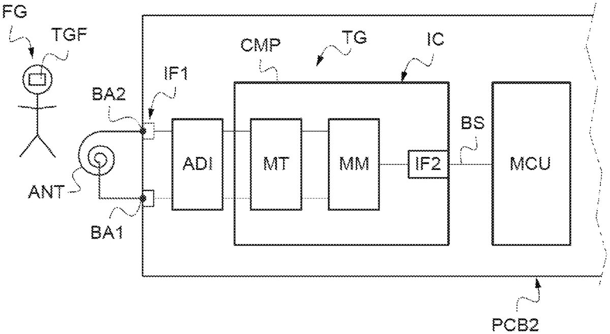
DETAILED DESCRIPTION InFIG.1, the reference TG denotes a contactless transponder. In this example, the transponder, used in reader mode, is configured to communicate with a figurine FG or an object fitted with another contactless transponder TGF, for example a tag, via its antenna ANT by using a carrier signal having a frequency of for example 13.56 MHz. The figurine or the object may be a statuette, a playing card, a packaging label, or any other object that can be fitted with a transponder The transponder TG is in this case a transponder that is capable of communicating in accordance with a contactless communication protocol that uses near-field communication (NFC) technology, for example. This transponder TG, incorporated here within a video game device, is for example intended to read characteristics of the figurine that are stored in a memory of the transponder TGF so as to allow the player to play as a character corresponding to said figurine FG. This transponder TG comprises an integrated circuit IC, for example an integrated circuit of the ST25 family marketed by STMicroelectronics. The transponder TG includes two terminals AC0and AC1that are connected, respectively, to the two terminals of the antenna ANT. The two terminals AC0and AC1in this case form a first contactless communication interface IF1of the transponder. The integrated circuit IC forms a contactless component CMP and also includes processing circuitry MT, including for example an energy recovery circuit, a microprocessor and/or a wired logic unit. The processing circuitry MT are in particular configured to process the information received from the transponder TFG of the figurine. The transponder TG also includes, as is conventional, an impedance-matching network ADI forming, with the antenna ANT1, a resonant circuit at the carrier frequency, in this case 13.56 MHz. The integrated circuit IC also includes a second communication ...
DETAILED DESCRIPTION
InFIG.1, the reference TG denotes a contactless transponder. In this example, the transponder, used in reader mode, is configured to communicate with a figurine FG or an object fitted with another contactless transponder TGF, for example a tag, via its antenna ANT by using a carrier signal having a frequency of for example 13.56 MHz. The figurine or the object may be a statuette, a playing card, a packaging label, or any other object that can be fitted with a transponder
The transponder TG is in this case a transponder that is capable of communicating in accordance with a contactless communication protocol that uses near-field communication (NFC) technology, for example.
This transponder TG, incorporated here within a video game device, is for example intended to read characteristics of the figurine that are stored in a memory of the transponder TGF so as to allow the player to play as a character corresponding to said figurine FG.
This transponder TG comprises an integrated circuit IC, for example an integrated circuit of the ST25 family marketed by STMicroelectronics.
The transponder TG includes two terminals AC0and AC1that are connected, respectively, to the two terminals of the antenna ANT.
The two terminals AC0and AC1in this case form a first contactless communication interface IF1of the transponder.
The integrated circuit IC forms a contactless component CMP and also includes processing circuitry MT, including for example an energy recovery circuit, a microprocessor and/or a wired logic unit.
The processing circuitry MT are in particular configured to process the information received from the transponder TFG of the figurine.
The transponder TG also includes, as is conventional, an impedance-matching network ADI forming, with the antenna ANT1, a resonant circuit at the carrier frequency, in this case 13.56 MHz.
The integrated circuit IC also includes a second communication interface IF2, in this case an I2C interface linked, by an I2C bus, referenced BS, to a processing unit external to the integrated circuit, referenced MCU, for example a microcontroller. As is conventional, the microcontroller MCU is the master device on the bus BS, and the communication interface IF2is a slave device.
The microcontroller MCU is used in particular to manage and to control the video game.
A memory means MM is coupled between the processing circuitry MT and the second communication interface IF2.
The transponder TG is here a dynamic transponder acting as a gateway for the transmission of information from the figurine to the microcontroller MCU.
In other applications, the transponder TG may also act as a gateway for the transmission of information from the microcontroller MCU to another contactless device.
In NFC technology, information or data are generally transmitted in the form of frames, as is the case for example for the Type A protocol of the ISO-14443 standard.
The exchanged frames contain headers, data bits and parity bits.
The processing circuitry MT are therefore configured to extract, on reception, the data from the frames received from the figurine FG so as to write them to the memory means MM.
The microcontroller MCU is then configured to read these data from the memory means MM via the second communication interface IF2.
The transponder TG and the microcontroller MCU are borne by a printed circuit board bearing the reference PCB2.
The printed circuit board PCB2is housed in a device DIS (FIG.2), here a video game device.
This device DIS here takes the form of a controller handset possessing a housing1having an upper face10from which a control element2protrudes.
FIG.3shows an overall view of the control element2.
It includes a base20and a joystick21that is articulated to and coupled to the base20so as to allow the movement of a character for example or the movement of a cursor on a screen, for example a screen of the video game device itself or a television screen for example, to be controlled. The joystick21may be referred to as a control member.
As will be seen in greater detail below, the control element2also includes a printed circuit board that is connected, by a connector23, to the printed circuit board PCB2.
As illustrated in greater detail inFIG.4, the base20of the control element includes here two lugs201and202that allow the base to be secured to the printed circuit board PCB2.
The base also includes a cavity200within which the joystick21articulates.
As illustrated in greater detail inFIG.5, the joystick21includes a shaft210having a lower end211that cooperates with the cavity200in the base for the articulation of the joystick in three dimensions. The lower end211may be referred to as a first end of the joystick21.
The joystick also includes, opposite the lower end211, a free end, which is circular in shape, possessing here a groove2120covered with a cover2130. The free end may be referred to as a second end of the joystick21.
Additionally, as will be seen in greater detail below, this groove2120will house for example the antenna ANT of the transponder TG.
Lastly, as illustrated in greater detail inFIG.6and as mentioned above, the control element2includes a printed circuit board PCB1that is connected to the printed circuit board PCB2by the connector23.
Reference is now made more particularly toFIG.7, which schematically illustrates one exemplary configuration of the antenna ANT.
As mentioned above, the antenna ANT is housed in the groove2120that is located at the free end of the joystick21.
This free end protrudes from the top of the housing1of the handset.
In the example illustrated here, the antenna ANT is circular and comprises a plurality of turns.
By way of nonlimiting indication, the diameter of the antenna is for example 1.6 cm. Its resistance at 13.56 MHz is 1 ohm and it has an induction value of about 500 nH.
Since the antenna ANT is located in the control element, it is away from the metal elements of the game device, thereby improving contactless communication while avoiding the use of ferrite sheets. Furthermore, using an element of the game device that is already present (the joystick) to house the antenna provides a cost saving.
The control element2includes here two first electrically conductive linking means212and213. These two means212and213are, for example, metal tracks leading into the shaft210of the joystick21of the control element2. The electrically conductive linking means212,213may be referred to as electrical connectors.
These two metal tracks possess two first ends214and215, respectively.
These two first ends214and215are connected, respectively, to the two terminals BA1and BA2of the antenna ANT.
The two tracks212and213further possess two second ends216and217that are located opposite the two first ends214and215.
The device then further comprises two second electrically conductive linking means24coupling the two second ends216and217to the impedance-matching circuit ADI.
In the example described here, the second linking means24includes flexible connecting means240, possessing here two flexible cables2400,2401, that are connected between the two second ends216and217and metal tracks242and243of the printed circuit board PCB1, these metal tracks242and243being connected to the interface IF1of the board PCB2and consequently to the impedance-matching circuit ADI of the transponder TG. The flexible connecting means240may be referred to as a flexible connector.
As shown more precisely inFIG.8, the two second ends216and217may be provided with female and male connectors216C and217C. The female connector216C has a first shape configured to receive a corresponding male connector with a second shape, and the male connector217C has a third shape configured to receive a corresponding female connector with a fourth shape.
As illustrated inFIG.9, the flexible connecting means240may themselves be fitted with a male and female connector2430that is intended to cooperate with the connectors216C and217C. The flexible connecting means240further include, at the other end, another connector2420that is intended to be connected to the printed circuit board PCB1so as to cooperate with the metal tracks242and243. The female connector2430has a first shape configured to receive a corresponding male connector with a second shape, and the male connector2430has a third shape configured to receive a corresponding female connector with a fourth shape.
Of course, the length of the flexible connecting means240is chosen so as to maintain an electrical connection while not hindering the movement of the joystick articulated to its base.
FIG.10is another schematic view showing the connection of the flexible connecting means240to the printed circuit board PCB1and the metal tracks242and243that route to the printed circuit board PCB1.
The disclosure is not limited to the embodiments that have been described, but encompasses all variants.
Thus, as illustrated inFIG.11, it would be possible for the flexible connecting means2400and2401, which are connected to the two second ends216and217of the first linking means, to be connected to electrically conductive securing screws250and251. These securing screws allow the base20to be secured to the control element at the site of the lugs201and202(FIG.4) and they come into contact with the metal tracks242and243so as to make an electrical connection from the antenna to the impedance-matching circuit.
Furthermore, although only one antenna has been shown, it would be possible for the handset1to include a plurality of antennas located, respectively, within a plurality of protruding elements. These antennas would then be connected in parallel and all linked to the impedance-matching circuit.
Furthermore, although the game device has been shown in this exemplary embodiment in the form of a handset, it would of course be possible for the device to include a console that is distinct from the handset including the control element.
The game device could also have a plurality of controller handsets.
The control element could also be a control button protruding from the housing of the controller handset.
The various embodiments described above can be combined to provide further embodiments.
These and other changes can be made to the embodiments in light of the above-detailed description. In general, in the following claims, the terms used should not be construed to limit the claims to the specific embodiments disclosed in the specification and the claims, but should be construed to include all possible embodiments along with the full scope of equivalents to which such claims are entitled. Accordingly, the claims are not limited by the disclosure.
Claims
- A device, comprising: a base;a joystick control member articulated to the base, the joystick control member configured to, in operation, articulate relative to the base to provide electrical inputs, and the joystick control member includes: a first end received by the base;a second end spaced apart from the first end;and a shaft extending between the first end and the second end, the shaft coupling the first end to the second end;a contactless transponder on the second end of the joystick control member, the contactless transponder including an antenna;a first conductive track having a first end coupled to the contactless transponder and a second end adjacent to the second end of the joystick control member;and a second conductive track having a first end coupled to the contactless transponder and a second end adjacent to the second end of the joystick control member.
- The device according to claim 1, wherein the base includes a cavity that receives the first end of the joystick control member.
- The device according to claim 1, wherein the second end of the joystick control member includes a groove that receives the antenna of the contactless transponder.
- The device according to claim 3, wherein a cover covers the second end of the joystick control member and the antenna of the contactless transponder.
- The device according to claim 1, further comprising: a printed circuit board including an electrically conductive track and housed in the base;an electrical connector coupled to the contactless transponder, the electrical connector extends along the shaft;and a flexible connector housed within the base, the flexible connector electrically coupled between the electrically conductive track of printed circuit board and the electrical connector.
- The device according to claim 5, wherein the electrical connector includes a first end having a first shape and the flexible connector includes a second end with a second shape, the first end having the first shape is configured to be coupled to the second end having the second shape.
- The device according to claim 1, wherein the antenna of the contactless transponder has a circular shape.
- A device, comprising: a base;a joystick control member articulated to the base, the joystick control member including a first end, a second end opposite the first end, and a shaft coupling the first end to the second end, the joystick control member configured to, in operation, articulate with respect to the base to provide electrical inputs;a contactless transponder on the second end of the joystick control member;a first conductive track having a first end coupled to the contactless transponder and a second end adjacent to the second end of the joystick control member;and a second conductive track having a first end coupled to the contactless transponder and a second end adjacent to the second end of the joystick control member.
- The device according to claim 8, wherein the second end of the first conductive track is coupled to a male connector and the second end of the second conductive track is coupled to a female connector.
- The device according to claim 8, further comprising a groove in the second end of the joystick control member that receives an antenna of the contactless transponder.
- The device according to claim 8, wherein the second end of the joystick control member is a free end of the joystick control member configured to, in operation, be freely articulated by a user to provide the electrical inputs.
- The device of claim 8, wherein the contactless transponder is configured to, in operation, scan an RFID tag.
- A device, comprising: a base;a joystick control member articulated to the base, the joystick control member including a first end, a second end opposite to the first end, and a shaft coupling the first end to the second end, the joystick control member configured to, in operation, articulate with respect to the base to provide electrical inputs;a contactless transponder on the second end of the joystick control member;a first conductive track having a first end coupled to the contactless transponder and a second end adjacent to the second end of the joystick control member;a second conductive track having a first end coupled to the contactless transponder and a second end adjacent to the second end of the joystick control member;and a cover on the second end of the joystick control member, and the cover covers an antenna of the contactless transponder.
- The device of claim 13, wherein the second end of the joystick control member is a free end of the joystick control member configured to, in operation, be freely articulated by a user to provide the electrical inputs.
- The device of claim 13, wherein: the joystick control member further includes a groove in the second end of the joystick control member;and the contactless transponder includes an antenna housed within the groove.
- The device of claim 15, wherein the antenna includes a plurality of turns.
- The device of claim 15, wherein the antenna of the contactless transponder is configured to scan an object fitted with another contactless transponder.
- The device of claim 13, further comprising: a first connector at the first end of the joystick control member and coupled to the second end of the first conductive track;and a second connector at the first end of the joystick control member and coupled to the second end of the second conductive track.
- The device of claim 18, wherein: the first connector is a female connector;and the second connector is a male connector.
- The device of claim 13, wherein the joystick control member is a joystick shaft structure.
Disclaimer: Data collected from the USPTO and may be malformed, incomplete, and/or otherwise inaccurate.