U.S. Pat. No. 11,907,412
CONTEXTUAL SPECTATOR INCLUSION IN A VIRTUAL REALITY EXPERIENCE
AssigneeInternational Business Machines Corp
Issue DateSeptember 28, 2020
Illustrative Figure
Abstract
A method of generating a virtual reality (“VR”) experience includes detecting, using external sensors, a real-world spectator that is in a spectator space that is adjacent to a user that is wearing a VR headset and experiencing a VR space. The method also includes detecting a real-world physical state of the spectator, and rendering, in response to detecting, the spectator in the VR space as an avatar that reflects the real-world physical state of the spectator.
Description
DETAILED DESCRIPTION Intertwining the experience of the adjacent spectators and the user's VR experience, such as a game or cinema, can be beneficial to all parties. Therefore, the present disclosure presents a system and method wherein sensors (e.g., external cameras) can capture nearby adjacent individuals and render them into the VR space with appropriate context to the simulation and use visual cues to reflect their emotional and physical state in an avatar. For one example, a user is playing a VR game while a spectator is in the room. The user wishes that the experience was more collaborative outside of just speaking to the spectator, and the spectator feels likewise. The VR system, using the sensors, finds the spectator and renders an avatar representing the spectator into the VR space. If the user is playing a mystery-themed game, then the spectator can be rendered as a moving/talking/reacting painting on a wall, for example. When the spectator jumps up and exclaims in excitement, the user can hear the spectator (through sound waves in the air, as normally), but the VR painting will also reflect the spectator's movement and emotions. For another example, if there are two users in separate rooms playing a competitive VR game, then the spectators for each user can be virtualized into the VR experience. More specifically, the spectators' avatars can be populated into the VR space as fans in the stands of the gaming arena, for example. The software and hardware for these capabilities can be present in the VR system. The spectators can opt in to such a VR experience, and if they do, then motion capture equipment, such as sensors and/or cameras, can detect the spectators as long as they are physically inside of an active space proximate to the user. Then, the avatars can ...
DETAILED DESCRIPTION
Intertwining the experience of the adjacent spectators and the user's VR experience, such as a game or cinema, can be beneficial to all parties. Therefore, the present disclosure presents a system and method wherein sensors (e.g., external cameras) can capture nearby adjacent individuals and render them into the VR space with appropriate context to the simulation and use visual cues to reflect their emotional and physical state in an avatar.
For one example, a user is playing a VR game while a spectator is in the room. The user wishes that the experience was more collaborative outside of just speaking to the spectator, and the spectator feels likewise. The VR system, using the sensors, finds the spectator and renders an avatar representing the spectator into the VR space. If the user is playing a mystery-themed game, then the spectator can be rendered as a moving/talking/reacting painting on a wall, for example. When the spectator jumps up and exclaims in excitement, the user can hear the spectator (through sound waves in the air, as normally), but the VR painting will also reflect the spectator's movement and emotions. For another example, if there are two users in separate rooms playing a competitive VR game, then the spectators for each user can be virtualized into the VR experience. More specifically, the spectators' avatars can be populated into the VR space as fans in the stands of the gaming arena, for example.
The software and hardware for these capabilities can be present in the VR system. The spectators can opt in to such a VR experience, and if they do, then motion capture equipment, such as sensors and/or cameras, can detect the spectators as long as they are physically inside of an active space proximate to the user. Then, the avatars can be rendered with expressions and movements (including mouth movements) that reflect the expressions and movements from their respective spectators. In addition, if a spectator leaves the active space, the system will animate the exit of their avatar in such a way that indicates that the spectator has left without being disturbing to the user. Similarly, if a spectator who has opted-in reenters the active space, the system will animate the entrance of their avatar in such a way that indicates that the spectator has rejoined the active space.
The avatars can be rendered in different locations which may correspond to or differ from the spectators' locations with respect to the user. The avatars can be predefined, for example, by each spectator, by the VR experience, or they can be generated using the context of the VR experience. For one example, the avatars can be generated using the form of animals or objects appropriate for the theme of the VR experience, such as, but not limited to, as bats in a VR experience in a cave or an abandoned home, as horse-flies in a VR experience involving horses, as painting on a wall in a building, etc.
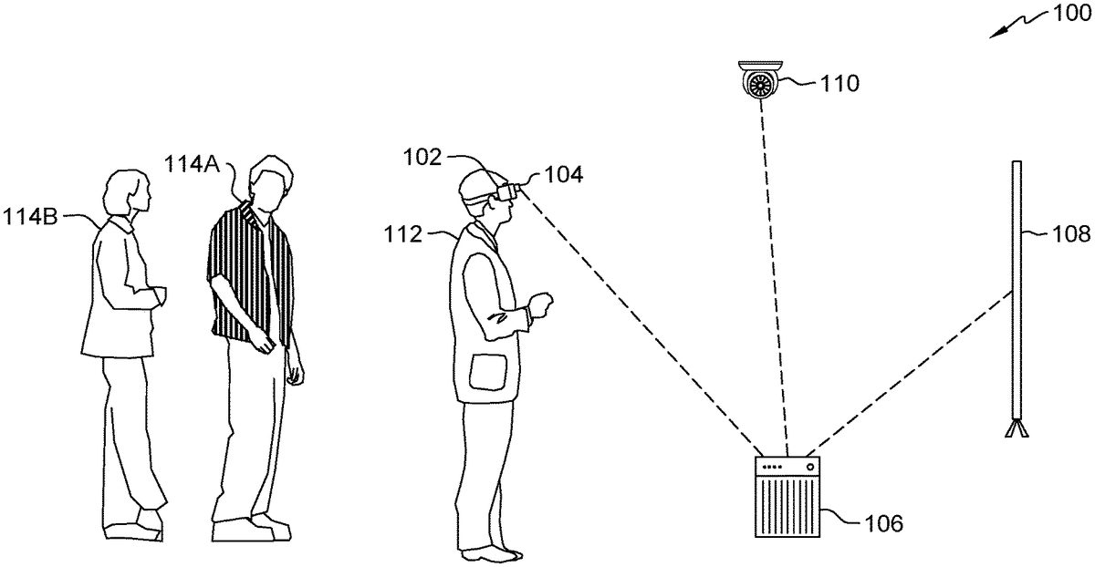
Referring now to the Figures,FIG.1shows VR system100which comprises VR headset102, headset camera104, VR controller106, display device108, and ceiling-mounted camera110. These components of VR system100are wirelessly connected together to provide a VR experience for user112who is wearing VR headset102. In addition, display device108can show various portions of the VR experience (e.g., the view that user112is seeing) to allow persons114A and114B (collectively, “people114”) to see and participate in the VR experience.
In the illustrated embodiment, cameras104and/or110monitor a spectator area, which is an area proximate to user112. For example, the spectator area can be the size of a room or a performance area, a 1 m to 5 m radius around user112, or a 1.5 m to 4 m radius around user112. Cameras104and/or110can include additional sensors, such as microphones. The information from cameras104and110can be sent to and analyzed by VR controller106. VR controller106can detect and monitor people114in the spectator area. Furthermore, VR controller106can analyze people114to determine whether they are spectators (showing interest in the VR experience) or bystanders (present but uninvolved with the VR experience).
If VR controller106determines that one or more of people114are spectators, then VR controller106can prompt them to opt-in to the VR experience. This can occur, for example, using display device108and/or cameras104and/or110. If any of people114wish to join the experience, they can acknowledge, for example, using a gesture or verbal speech. Once some or all of people114have opted-in, then they can be added to the VR space that is viewable by user112. Thereby, any of people114who want to be spectators can be involved in the VR experience instead of merely observing it.
FIG.2shows VR view200of the VR space, for example, from the inside of VR headset102as user112would see it. VR view200includes avatars214A and214B (collectively, “avatars214”), desk216, book218, pen220, ink222, painting224, and spiderweb226. Because VR view200takes place in the greater context of the real world (shown inFIG.1), references may be made to the features ofFIG.1.
In the illustrated embodiment, people114have been recognized as spectators in the spectator space and have opted-in to the VR experience. Therefore, avatar214A has been rendered in VR view200to represent person114A, and avatar214B has been rendered in VR view200to represent person114B. Because cameras104and/or110can determine the relative and/or absolute locations of people114with respect to user112(for example, using temporal parallax), avatars214are sized and positioned accordingly in the VR space. For example, because person114A is closer than person114B to user112in the real world, avatar214A appears larger than avatar214B in VR view200.
In the illustrated embodiment, avatars214have the form of bats, although there are many other forms that avatars214could take. For example, the avatar forms can be human or non-human; animal, machine, or fantasy creature; stationary (e.g., painting224) or mobile (e.g., with the ability to swim, crawl, walk, roll, and/or fly). Thereby, the avatar forms can be, for example, birds, bats, insects (e.g., flies, beetles, or spiders), drones, balloons, fairies, sprites, or ghosts.
In some embodiments, VR controller106has a predetermined set of avatar forms that can be chosen from by user112and/or the corresponding person114. In some embodiments, the VR experience (i.e., the software being run by VR controller106) will have a list of predetermined avatar forms. In some embodiments, VR controller106can suggest, restrict, or choose the available avatar forms based on the context of the VR experience. The context of the VR experience can be determined in a number of ways using, for example, a convolutional neural network (“CNN”). For example, VR controller106can use natural language processing (“NLP”) to analyze a description of the current VR experience (e.g., from the product literature of the software or from publicly available reviews on the Internet). For another example, VR controller106can classify the environment and/or ambience of the VR experience. For another example, VR controller106can analyze the objects that are near user112in the VR space. For another example, VR controller106can analyze VR view200(e.g., the lighting effects). For another example, VR controller106can analyze words, sounds, and/or music in the VR experience. During the analysis of the context of the VR experience, factors such as color themes, geography, wildlife, characters, architecture, vehicles, apparel, language, speech patterns, time period, fictional beings, and/or non-player characters (“NPCs”) can be taken into consideration. For example, because the VR experience being depicted inFIG.2is that of an abandoned home (e.g., as evidenced by spiderweb226), avatars214have the form of bats to reflect the spooky environment.
In addition to the form, in some embodiments, the appearance of avatars214can be customized to reflect the real-world physical state of their corresponding people114. The physical state of a person114can include their appearance, motions, expressions, and sounds (e.g., utterances and noises). While sometimes the reflection of people114in avatars214is identical, other times the reflection is modified. For examples related to appearances, in some embodiments, an avatar214can include a rendering of the face of its corresponding person114(although other embodiments are face-blind). In some embodiments, an avatar214can include a color and/or pattern of the apparel being worn by its corresponding person114. For example, avatar214A has black-and-white stripes on its wings to reflect the black-and-white stripes on the shirt of person114A. For examples of motions, in some embodiments, movements of the body and large gestures by people114are monitored by VR system100and reflected in the VR state of the respective avatars214. This can include relative motion between user112and people114, as well as movements in place such as jumping or arm waving. For examples of expressions, in some embodiments, subtle movements of extremities and/or static poses including facial expressions and hand gestures can be reflected in the VR state of the respective avatars214.
For examples of sounds, in some embodiments, utterances (e.g., spoken words or yelling) and noises (e.g., clapping) can be reflected in the VR states of avatars214. Because user112can hear the sounds from people114through the air in a normal manner, reflecting the sounds in the VR states of avatars214may be done in ways besides generating more sound in the VR experience. For example, the colors of avatars214can be changed depending on the types of sounds (or lack thereof) from people114. However, in an embodiment where there is a large stadium of VR fans (e.g., in a sports arena), the sounds of people114can be transformed in such a way to make it sound like there is a whole stadium of people making those sounds. Furthermore, in such embodiments, avatars214can compose the same number of VR fans as there are people114. Alternatively, more VR fans can be in the form of avatars214that reflect the physical states of people114. In addition, when significant events occur in the VR experience, the VR fans could represent the physical states of people114, essentially becoming avatars214in a more limited sense (e.g., their appearances may stay the same but their movements may reflect those of people114).
Because avatars214can reflect the physical states of people114, avatars214reflect the emotional states of people114. This can allow user112to see the reactions of people114to the VR experience such that people114are both witnessing the VR experience and adding to the VR experience. This can provide a more satisfying experience for both people114and user112and can also allow people114to give non-verbal feedback to user112. For example, if the VR experience is a tour of a proposed building designed by user112, people114(e.g., the customers) can follow the tour and engage with user112. This can allow user112to gauge the enthusiasm of people114for the design, as well as allow people114to point to places that they want the tour to go to without having to verbally explain them in detail.
FIG.3shows a flowchart of method300of generating a VR experience. During the discussion of method300, references may be made to the features ofFIGS.1and2. In the illustrated embodiment, at block302, user112initializes VR system100, and opts-in to including avatars214of spectators in the VR experience. At block304, VR system100recognizes people114in the spectator area and determines whether they are spectators or bystanders. The determination at block304can be made for each person114separately based on, for example, tracking of eye movements of each person114. More specifically, if a person114is watching display device108for a significant amount or percentage of time, then the person114is considered a spectator. On the other hand, if the person114is not looking at display device108a significant amount or percentage of the time (e.g., if they are doing another activity in the spectator area, such as reading), then the person114is considered a bystander, in some embodiments.
At block306, any people114deemed spectators (e.g., person114A and person114B) are asked to opt-in to the VR experience. If they do, then VR system100makes a note of their appearance to identify, monitor, and track them, for example, to place their avatar214in the correct location in the VR space and to make their avatar214have the proper appearance to reflect the physical state of their person114. At block308, the VR experience is started. At block310, the forms of avatars214are chosen. The determination at block310can be made by, for example, a mandate from the VR experience software, generic forms available in VR system100, analysis of the context of the VR experience, and/or choice by user112or people114. Furthermore, avatars214can be customized based on the real-world appearances of people114.
At block312, people114are monitored by VR system100, and avatars214are rendered in VR view200to reflect the real-world physical states of people114, respectively. Block312can last until the end of the VR experience. However, additional steps can occur in some situations that may occur during the VR experience. For example, if another person114enters the spectator area after block308, this person114can be detected by VR system100. Then, VR system100can execute steps (a la blocks304and306) to determine if this person114is a spectator. If so, then VR system100can ask this person114to opt-in in a manner that does not disturb user112. For example, the opt-in request can be presented on display device108but not in VR headset102or VR view200. Then this person114can use sound and/or motion to accept. Then VR system100can continue to monitor people114(including this new person114) at block312.
For another example of additional steps, during the VR experience, person114A may exit the spectator area. In such a situation, it may be jarring or distracting to user112if avatar214A were to instantaneously disappear. Therefore, an animation can be played to indicate that person114A is no longer considered a spectator. Such animations can be, for example, avatar214A flying away, going through a portal, fading away (e.g., increasing the transparency), or disappearing into a cloud of smoke. Such animations can ease the transition from avatar214A existing to being absent, although sometimes attention may want to be called to the departure of avatar214A. In that case, a more dramatic effect can be used, such as avatar214A evaporating in a burst of electricity. Similarly, when VR system100recognizes that person114A has returned to the spectator area, another animation can be played. Such entering animations can be reversals of the exiting animations, or they can be their own distinct animations. It should be noted that the exiting and entering animations can be played when any of people114cease or resume being spectators, respectively, due to whether they are paying attention to the VR experience (e.g., looking at display device108). Furthermore, the entering animation can be played after person114A opts-in to the VR experience and their avatar form is chosen and customized, which introduces avatar214A into the VR experience.
In addition, in some embodiments, avatars214are rendered depending on the activity of people114. For example, if people114are quietly watching display device108, then avatars214may be absent from VR view200. But when people114begin jumping and cheering (e.g., because of an exciting event in the VR experience), then avatars214can be rendered. Furthermore, VR controller106can record or annotate (a.k.a., tag) a recording of the VR experience in response to a dramatic and/or loud expression by people114. Such a recording or annotation can allow user112to review the most exciting portions of the VR experience, for example, to make a highlight reel. In some embodiments, audience participation can be factored into the VR experience in other ways than just avatars214. For example, dramatic and/or loud expressions by people114can boost the abilities, score, and/or experience points of user112, which further closes the gap between a player and their spectators (e.g., in an e-sport VR experience).
Referring now toFIG.4, shown is a high-level block diagram of an example computer system (i.e., computer)11that may be used in implementing one or more of the methods or modules, and any related functions or operations, described herein (e.g., using one or more processor circuits or computer processors of the computer), in accordance with embodiments of the present disclosure. For example, computer system11can be used for VR headset102, VR controller106, and display device108(shown inFIG.1). In some embodiments, the components of the computer system11may comprise one or more CPUs12, a memory subsystem14, a terminal interface22, a storage interface24, an I/O (Input/Output) device interface26, and a network interface29, all of which may be communicatively coupled, directly or indirectly, for inter-component communication via a memory bus13, an I/O bus19, and an I/O bus interface unit20.
The computer system11may contain one or more general-purpose programmable central processing units (CPUs)12A,12B,12C, and12D, herein generically referred to as the processer12. In some embodiments, the computer system11may contain multiple processors typical of a relatively large system; however, in other embodiments the computer system11may alternatively be a single CPU system. Each CPU12may execute instructions stored in the memory subsystem14and may comprise one or more levels of on-board cache.
In some embodiments, the memory subsystem14may comprise a random-access semiconductor memory, storage device, or storage medium (either volatile or non-volatile) for storing data and programs. In some embodiments, the memory subsystem14may represent the entire virtual memory of the computer system11and may also include the virtual memory of other computer systems coupled to the computer system11or connected via a network. The memory subsystem14may be conceptually a single monolithic entity, but, in some embodiments, the memory subsystem14may be a more complex arrangement, such as a hierarchy of caches and other memory devices. For example, memory may exist in multiple levels of caches, and these caches may be further divided by function, so that one cache holds instructions while another holds non-instruction data, which is used by the processor or processors. Memory may be further distributed and associated with different CPUs or sets of CPUs, as is known in any of various so-called non-uniform memory access (NUMA) computer architectures. In some embodiments, the main memory or memory subsystem14may contain elements for control and flow of memory used by the processor12. This may include a memory controller15.
Although the memory bus13is shown inFIG.4as a single bus structure providing a direct communication path among the CPUs12, the memory subsystem14, and the I/O bus interface20, the memory bus13may, in some embodiments, comprise multiple different buses or communication paths, which may be arranged in any of various forms, such as point-to-point links in hierarchical, star or web configurations, multiple hierarchical buses, parallel and redundant paths, or any other appropriate type of configuration. Furthermore, while the I/O bus interface20and the I/O bus19are shown as single respective units, the computer system11may, in some embodiments, contain multiple I/O bus interface units20, multiple I/O buses19, or both. Further, while multiple I/O interface units are shown, which separate the I/O bus19from various communications paths running to the various I/O devices, in other embodiments some or all of the I/O devices may be connected directly to one or more system I/O buses.
In some embodiments, the computer system11may be a multi-user mainframe computer system, a single-user system, or a server computer or similar device that has little or no direct user interface but receives requests from other computer systems (clients). Further, in some embodiments, the computer system11may be implemented as a desktop computer, portable computer, laptop or notebook computer, tablet computer, pocket computer, telephone, smart phone, mobile device, or any other appropriate type of electronic device.
In the illustrated embodiment, memory subsystem14further includes VR experience software30. The execution of VR experience software30enables computer system11to perform one or more of the functions described above in operating a VR experience, including detecting and monitoring people114and rendering avatars214A and214B in the VR space if appropriate (for example, blocks302-312shown inFIG.3).
It is noted thatFIG.4is intended to depict representative components of an exemplary computer system11. In some embodiments, however, individual components may have greater or lesser complexity than as represented inFIG.4, components other than or in addition to those shown inFIG.4may be present, and the number, type, and configuration of such components may vary.
The present invention may be a system, a method, and/or a computer program product at any possible technical detail level of integration. The computer program product may include a computer readable storage medium (or media) having computer readable program instructions thereon for causing a processor to carry out aspects of the present invention.
The computer readable storage medium can be a tangible device that can retain and store instructions for use by an instruction execution device. The computer readable storage medium may be, for example, but is not limited to, an electronic storage device, a magnetic storage device, an optical storage device, an electromagnetic storage device, a semiconductor storage device, or any suitable combination of the foregoing. A non-exhaustive list of more specific examples of the computer readable storage medium includes the following: a portable computer diskette, a hard disk, a random access memory (RAM), a read-only memory (ROM), an erasable programmable read-only memory (EPROM or Flash memory), a static random access memory (SRAM), a portable compact disc read-only memory (CD-ROM), a digital versatile disk (DVD), a memory stick, a floppy disk, a mechanically encoded device such as punch-cards or raised structures in a groove having instructions recorded thereon, and any suitable combination of the foregoing. A computer readable storage medium, as used herein, is not to be construed as being transitory signals per se, such as radio waves or other freely propagating electromagnetic waves, electromagnetic waves propagating through a waveguide or other transmission media (e.g., light pulses passing through a fiber-optic cable), or electrical signals transmitted through a wire.
Computer readable program instructions described herein can be downloaded to respective computing/processing devices from a computer readable storage medium or to an external computer or external storage device via a network, for example, the Internet, a local area network, a wide area network and/or a wireless network. The network may comprise copper transmission cables, optical transmission fibers, wireless transmission, routers, firewalls, switches, gateway computers and/or edge servers. A network adapter card or network interface in each computing/processing device receives computer readable program instructions from the network and forwards the computer readable program instructions for storage in a computer readable storage medium within the respective computing/processing device.
Computer readable program instructions for carrying out operations of the present invention may be assembler instructions, instruction-set-architecture (ISA) instructions, machine instructions, machine dependent instructions, microcode, firmware instructions, state-setting data, configuration data for integrated circuitry, or either source code or object code written in any combination of one or more programming languages, including an object oriented programming language such as Smalltalk, C++, or the like, and procedural programming languages, such as the “C” programming language or similar programming languages. The computer readable program instructions may execute entirely on the user's computer, partly on the user's computer, as a stand-alone software package, partly on the user's computer and partly on a remote computer or entirely on the remote computer or server. In the latter scenario, the remote computer may be connected to the user's computer through any type of network, including a local area network (LAN) or a wide area network (WAN), or the connection may be made to an external computer (for example, through the Internet using an Internet Service Provider). In some embodiments, electronic circuitry including, for example, programmable logic circuitry, field-programmable gate arrays (FPGA), or programmable logic arrays (PLA) may execute the computer readable program instructions by utilizing state information of the computer readable program instructions to personalize the electronic circuitry, in order to perform aspects of the present invention.
Aspects of the present invention are described herein with reference to flowchart illustrations and/or block diagrams of methods, apparatus (systems), and computer program products according to embodiments of the invention. It will be understood that each block of the flowchart illustrations and/or block diagrams, and combinations of blocks in the flowchart illustrations and/or block diagrams, can be implemented by computer readable program instructions.
These computer readable program instructions may be provided to a processor of a general purpose computer, special purpose computer, or other programmable data processing apparatus to produce a machine, such that the instructions, which execute via the processor of the computer or other programmable data processing apparatus, create means for implementing the functions/acts specified in the flowchart and/or block diagram block or blocks. These computer readable program instructions may also be stored in a computer readable storage medium that can direct a computer, a programmable data processing apparatus, and/or other devices to function in a particular manner, such that the computer readable storage medium having instructions stored therein comprises an article of manufacture including instructions which implement aspects of the function/act specified in the flowchart and/or block diagram block or blocks.
The computer readable program instructions may also be loaded onto a computer, other programmable data processing apparatus, or other device to cause a series of operational steps to be performed on the computer, other programmable apparatus or other device to produce a computer implemented process, such that the instructions which execute on the computer, other programmable apparatus, or other device implement the functions/acts specified in the flowchart and/or block diagram block or blocks.
The flowchart and block diagrams in the Figures illustrate the architecture, functionality, and operation of possible implementations of systems, methods, and computer program products according to various embodiments of the present invention. In this regard, each block in the flowchart or block diagrams may represent a module, segment, or portion of instructions, which comprises one or more executable instructions for implementing the specified logical function(s). In some alternative implementations, the functions noted in the blocks may occur out of the order noted in the Figures. For example, two blocks shown in succession may, in fact, be executed substantially concurrently, or the blocks may sometimes be executed in the reverse order, depending upon the functionality involved. It will also be noted that each block of the block diagrams and/or flowchart illustration, and combinations of blocks in the block diagrams and/or flowchart illustration, can be implemented by special purpose hardware-based systems that perform the specified functions or acts or carry out combinations of special purpose hardware and computer instructions.
It is to be understood that although this disclosure includes a detailed description on cloud computing, implementation of the teachings recited herein are not limited to a cloud computing environment. Rather, embodiments of the present invention are capable of being implemented in conjunction with any other type of computing environment now known or later developed.
Cloud computing is a model of service delivery for enabling convenient, on-demand network access to a shared pool of configurable computing resources (e.g., networks, network bandwidth, servers, processing, memory, storage, applications, virtual machines, and services) that can be rapidly provisioned and released with minimal management effort or interaction with a provider of the service. This cloud model may include at least five characteristics, at least three service models, and at least four deployment models.
Characteristics are as follows:
On-demand self-service: a cloud consumer can unilaterally provision computing capabilities, such as server time and network storage, as needed automatically without requiring human interaction with the service's provider.
Broad network access: capabilities are available over a network and accessed through standard mechanisms that promote use by heterogeneous thin or thick client platforms (e.g., mobile phones, laptops, and PDAs).
Resource pooling: the provider's computing resources are pooled to serve multiple consumers using a multi-tenant model, with different physical and virtual resources dynamically assigned and reassigned according to demand. There is a sense of location independence in that the consumer generally has no control or knowledge over the exact location of the provided resources but may be able to specify location at a higher level of abstraction (e.g., country, state, or datacenter).
Rapid elasticity: capabilities can be rapidly and elastically provisioned, in some cases automatically, to quickly scale out and rapidly released to quickly scale in. To the consumer, the capabilities available for provisioning often appear to be unlimited and can be purchased in any quantity at any time.
Measured service: cloud systems automatically control and optimize resource use by leveraging a metering capability at some level of abstraction appropriate to the type of service (e.g., storage, processing, bandwidth, and active user accounts). Resource usage can be monitored, controlled, and reported, providing transparency for both the provider and consumer of the utilized service.
Service Models are as follows:
Software as a Service (SaaS): the capability provided to the consumer is to use the provider's applications running on a cloud infrastructure. The applications are accessible from various client devices through a thin client interface such as a web browser (e.g., web-based e-mail). The consumer does not manage or control the underlying cloud infrastructure including network, servers, operating systems, storage, or even individual application capabilities, with the possible exception of limited user-specific application configuration settings.
Platform as a Service (PaaS): the capability provided to the consumer is to deploy onto the cloud infrastructure consumer-created or acquired applications created using programming languages and tools supported by the provider. The consumer does not manage or control the underlying cloud infrastructure including networks, servers, operating systems, or storage, but has control over the deployed applications and possibly application hosting environment configurations.
Infrastructure as a Service (IaaS): the capability provided to the consumer is to provision processing, storage, networks, and other fundamental computing resources where the consumer is able to deploy and run arbitrary software, which can include operating systems and applications. The consumer does not manage or control the underlying cloud infrastructure but has control over operating systems, storage, deployed applications, and possibly limited control of select networking components (e.g., host firewalls).
Deployment Models are as follows:
Private cloud: the cloud infrastructure is operated solely for an organization. It may be managed by the organization or a third party and may exist on-premises or off-premises.
Community cloud: the cloud infrastructure is shared by several organizations and supports a specific community that has shared concerns (e.g., mission, security requirements, policy, and compliance considerations). It may be managed by the organizations or a third party and may exist on-premises or off-premises.
Public cloud: the cloud infrastructure is made available to the general public or a large industry group and is owned by an organization selling cloud services.
Hybrid cloud: the cloud infrastructure is a composition of two or more clouds (private, community, or public) that remain unique entities but are bound together by standardized or proprietary technology that enables data and application portability (e.g., cloud bursting for load-balancing between clouds).
A cloud computing environment is service oriented with a focus on statelessness, low coupling, modularity, and semantic interoperability. At the heart of cloud computing is an infrastructure that includes a network of interconnected nodes.
Referring now toFIG.5, illustrative cloud computing environment50is depicted. As shown, cloud computing environment50includes one or more cloud computing nodes10with which local computing devices used by cloud consumers, such as, for example, personal digital assistant (PDA) or cellular telephone54A, desktop computer54B, laptop computer54C, and/or automobile computer system54N may communicate. Nodes10may communicate with one another. They may be grouped (not shown) physically or virtually, in one or more networks, such as Private, Community, Public, or Hybrid clouds as described hereinabove, or a combination thereof. This allows cloud computing environment50to offer infrastructure, platforms and/or software as services for which a cloud consumer does not need to maintain resources on a local computing device. It is understood that the types of computing devices54A-N shown inFIG.5are intended to be illustrative only and that computing nodes10and cloud computing environment50can communicate with any type of computerized device over any type of network and/or network addressable connection (e.g., using a web browser).
Referring now toFIG.6, a set of functional abstraction layers provided by cloud computing environment50(FIG.5) is shown. It should be understood in advance that the components, layers, and functions shown inFIG.6are intended to be illustrative only and embodiments of the invention are not limited thereto. s depicted, the following layers and corresponding functions are provided:
Hardware and software layer60includes hardware and software components. Examples of hardware components include: mainframes61; RISC (Reduced Instruction Set Computer) architecture-based servers62; servers63; blade servers64; storage devices65; and networks and networking components66. In some embodiments, software components include network application server software67and database software68.
Virtualization layer70provides an abstraction layer from which the following examples of virtual entities may be provided: virtual servers71; virtual storage72; virtual networks73, including virtual private networks; virtual applications and operating systems74; and virtual clients75.
In one example, management layer80may provide the functions described below. Resource provisioning81provides dynamic procurement of computing resources and other resources that are utilized to perform tasks within the cloud computing environment. Metering and Pricing82provide cost tracking as resources are utilized within the cloud computing environment, and billing or invoicing for consumption of these resources. In one example, these resources may include application software licenses. Security provides identity verification for cloud consumers and tasks, as well as protection for data and other resources. User portal83provides access to the cloud computing environment for consumers and system administrators. Service level management84provides cloud computing resource allocation and management such that required service levels are met. Service Level Agreement (SLA) planning and fulfillment85provide pre-arrangement for, and procurement of, cloud computing resources for which a future requirement is anticipated in accordance with an SLA.
Workloads layer90provides examples of functionality for which the cloud computing environment may be utilized. Examples of workloads and functions which may be provided from this layer include: mapping and navigation91; software development and lifecycle management92; virtual classroom education delivery93; data analytics processing94; transaction processing95; and VR experience operation96.
The descriptions of the various embodiments of the present invention have been presented for purposes of illustration, but are not intended to be exhaustive or limited to the embodiments disclosed. Many modifications and variations will be apparent to those of ordinary skill in the art without departing from the scope and spirit of the described embodiments. The terminology used herein was chosen to best explain the principles of the embodiments, the practical application or technical improvement over technologies found in the marketplace, or to enable others of ordinary skill in the art to understand the embodiments disclosed herein.
Claims
- A method of generating a virtual reality (“VR”) experience, the method comprising: detecting, using external sensors, a real-world spectator that is in a spectator space that is adjacent to a user that is wearing a VR headset and experiencing a VR space;detecting a real-world physical state of the spectator comprising sounds of the spectator;rendering, in response to detecting the real-world physical state of the spectator, the spectator in the VR space as an avatar that reflects the real-world physical state of the spectator;rendering a plurality of VR fans in the VR space;boosting experience points of the user based on sounds from the spectator;and transforming the sounds of the spectator to make the sounds sound like they are being made by at least some of the plurality of VR fans;wherein the real-world physical state of the spectator reveals a real-world emotional state of the spectator;wherein the avatar reflects the real-world emotional state of the spectator;and wherein at least some of the plurality of VR fans reflect the real-world movements of the spectator, facial expressions of the spectator, or gestures of the spectator.
- The method of claim 1, wherein detecting the real-world physical state of the spectator is selected from the group consisting of detecting gestures of the spectator, detecting facial expressions of the spectator, detecting utterances of the spectator, and detecting noises of the spectator.
- The method of claim 1, wherein: the real-world physical state of the spectator includes apparel worn by the spectator;and the avatar is rendered to reflect a color and/or a pattern of the apparel.
- The method of claim 1, wherein a form of the avatar is a non-human entity.
- A virtual reality (“VR”) system comprising: a VR controller including one or more processors and a computer-readable storage medium coupled to the one or more processors storing program instructions, the VR controller being configured to generate a VR experience;a VR headset communicatively connected to the VR controller that is configured to display a VR space to a user;a sensor communicatively connected to the VR controller that is configured to monitor a spectator space proximate to the user;a display communicatively connected to the VR controller that is viewable from the spectator space;and boosting experience points of the user based on sounds from the spectator;wherein the program instructions, when executed by the one or more processors, cause the one or more processors to perform operations comprising: detecting, using the sensor, a first person in the spectator space;analyzing the first person to determine whether the first person is a spectator or a bystander based on whether the first person is engaged in another activity that is unrelated to the VR system;prompting, in response to determining that the first person is a spectator because the first person is not engaged in the another activity, the first person to opt-in to the VR experience;and rendering, in response to the first person opting-in, an avatar in the VR space that represents the spectator.
- The VR system of claim 5, wherein the sensor comprises: a first plurality of cameras mounted on the VR headset;and a second plurality of cameras that are mounted off of the VR headset.
- The VR system of claim 5, wherein rendering the avatar in the VR space that represents the spectator comprises: rendering an entrance animation in the VR space involving the avatar in response to the first person opting-in.
- The VR system of claim 5, wherein rendering the avatar in the VR space that represents the spectator comprises: rendering an exit animation in the VR space involving the avatar in response to the first person leaving the spectator space.
- The VR system of claim 8, wherein rendering the avatar in the VR space that represents the spectator comprises: rendering an entrance animation in the VR space involving the avatar in response to the first person reentering the spectator space.
- The VR system of claim 5, wherein the program instructions, when executed by the one or more processors, cause the one or more processors to perform operations further comprising: determining that the first person is no longer a spectator based on eye movements of the first person;and rendering an exit animation in the VR space involving the avatar in response to determining that the first person is no longer a spectator.
- The VR system of claim 5, wherein the program instructions, when executed by the one or more processors, cause the one or more processors to perform further operations comprising: detecting, using the sensor, a second person in the spectator space;analyzing the second person to determine whether the second person is a spectator or a bystander based on whether the second person is engaged in another activity that is unrelated to the VR system;determining that the second person is a bystander in response to the second person being engaged in the another activity;and declining to prompt, in response to determining that the second person is a bystander, the second person to opt-in to the VR experience.
- A method of generating a virtual reality (“VR”) experience, the method comprising: detecting, using external sensors, a real-world spectator that is in a spectator space that is adjacent to a user that is wearing a VR headset and experiencing a VR space;analyzing the VR space to determine a VR context, wherein analyzing the VR space to determine the VR context comprises analyzing music in the VR experience;rendering, in response to analyzing, the spectator in the VR space as an avatar that reflects the VR context;detecting a real-world physical state of the spectator comprising sounds of the spectator;rendering, in response to detecting the real-world physical state of the spectator, the spectator in the VR space as an avatar that reflects the real-world physical state of the spectator;boosting experience points of the user based on sounds from the spectator;and recording a portion of the VR experience in response to a dramatic and/or loud expression by the spectator.
- The method of claim 12, wherein a form of the avatar is a non-human entity.
- The method of claim 12, wherein analyzing the VR space to determine the VR context further comprises: analyzing the VR space for color themes, geography, wildlife, characters, architecture, vehicles, apparel, language, speech patterns, time period, and/or fictional beings.
- The method of claim 12, wherein analyzing the VR space to determine the VR context comprises: analyzing a description of the VR space.
- The method of claim 12, wherein rendering the spectator in the VR space comprises: selecting an avatar from a predetermined list of avatars for the VR context.
- The method of claim 12, wherein rendering the spectator in the VR space comprises: rendering an entrance animation in the VR space involving the avatar.
- The method of claim 12, wherein rendering the spectator in the VR space comprises: rendering an exit animation in the VR space involving the avatar in response to the real-world spectator leaving the spectator space.
Disclaimer: Data collected from the USPTO and may be malformed, incomplete, and/or otherwise inaccurate.