Illustrative Figure
Abstract
A video gaming system that preferable includes computing device interacting electronically with a video game controller, the video game controller in electronic communication with the computing device. Preferably, the computing device includes an electronic video game loaded on to a processor of the computing device when the video gaming system is configured to play a video game. Input signals, generated by the video game controller in response to an input action provided by a user of the video gaming system, cause a visual or audio response by the electronic video game, which is displayed on a display associated with the computing device or delivered by way of a speaker associated with the computing device.
Description
DETAILED DESCRIPTION The present disclosure generally relates to a video gaming system, which utilizes a video game controller in electronic communication with a computing device. Preferably, the computing device includes an electronic video game loaded on to a processor of the computing device when the video gaming system is configured to play a video game. As those skilled in the art further clearly recognize that input signals, generated by the video game controller, in response to an input action provided by a user of the video gaming system, causes a visual or audio response by the electronic video game, which is displayed on a display associated with the computing device or delivered by way of a speaker associated with the computing device. Accordingly, it is inherent that an operational video gaming system operates by way of a video game software program loaded into a memory portion of the computing device that interacts with the processor of the computing device. Further, for most video gaming systems, the video game controller preferably includes a processor, which manages the functions of the video game controller and interfaces with the processor of the computing device. Turning to the drawings.FIG.1shows a power management and power pass through circuit100(“PMPP”) of a first embodiment of a video gaming system101. Said video gaming system101, includes at least, but is not limited to, a computing device102, which provides at least a first energy storage device104. The computing device102communicates with a video game controller106, said video game controller106provides at least, but is not limited to, a second energy storage device108and a processor110. Said PMPP100precludes a simultaneous bidirectional current flow between said computing device102and said video game controller106. In a preferred embodiment, the communication between the computing device102and the video game controller106is achieved via a wired connection circuit112, however as one ...
DETAILED DESCRIPTION
The present disclosure generally relates to a video gaming system, which utilizes a video game controller in electronic communication with a computing device. Preferably, the computing device includes an electronic video game loaded on to a processor of the computing device when the video gaming system is configured to play a video game. As those skilled in the art further clearly recognize that input signals, generated by the video game controller, in response to an input action provided by a user of the video gaming system, causes a visual or audio response by the electronic video game, which is displayed on a display associated with the computing device or delivered by way of a speaker associated with the computing device. Accordingly, it is inherent that an operational video gaming system operates by way of a video game software program loaded into a memory portion of the computing device that interacts with the processor of the computing device. Further, for most video gaming systems, the video game controller preferably includes a processor, which manages the functions of the video game controller and interfaces with the processor of the computing device.
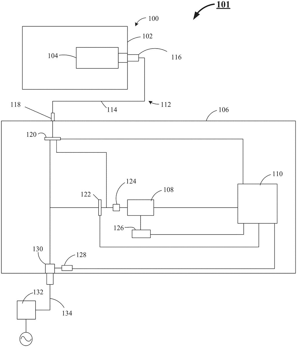
Turning to the drawings.FIG.1shows a power management and power pass through circuit100(“PMPP”) of a first embodiment of a video gaming system101. Said video gaming system101, includes at least, but is not limited to, a computing device102, which provides at least a first energy storage device104. The computing device102communicates with a video game controller106, said video game controller106provides at least, but is not limited to, a second energy storage device108and a processor110. Said PMPP100precludes a simultaneous bidirectional current flow between said computing device102and said video game controller106.
In a preferred embodiment, the communication between the computing device102and the video game controller106is achieved via a wired connection circuit112, however as one skilled in the art understands, communication between the computing device102and the video game controller106may be achieved wirelessly. The wired connection circuit112preferably includes a power and signal cable114(also referred to herein as cable114). Cable114preferably provides a connector116, which is specifically configured to interface with an interface connector118, said interface connector118provides a predetermined number of contacts including, but not limited to, a power contact and a ground contact.
As further shown byFIG.1, the video game controller106further provides at least, but not by way of a limitation: a first current flow control circuit120; a second current flow control circuit122; a unidirectional current flow circuit124; a battery charge control circuit126(battery charge control device); a voltage present detection circuit128; and an interface connector130. In a preferred embodiment, said interface connector130presents a structurally similar structure to the interface connector118. The PMPP100still further preferably includes a computing device charger132, and a charge cord134. In a preferred embodiment, during operation of the video gaming system101, the first energy storage device104is connected in parallel with the second energy storage device108of the video game controller106. The first energy storage device104and the second energy storage device108of the video game controller106are of a common voltage but are typically of different capacities.
Further in a preferred operating mode, when the computing device102is activated and no voltage is detected by the voltage present detection circuit128, the first current flow control circuit120is set to provide power from the first energy storage device104of the computing device102to the processor110by way of the unidirectional current flow circuit124and the second energy storage device108.
While the second current flow control circuit122is set to preclude power passage from the computing device charger132to the processor110, when voltage is detected by the voltage present detection circuit128, the first current flow control circuit120is set to preclude power from the first energy storage device104to the processor110. The first energy storage device104is simultaneously set to receive power from the computing device charger132for charging the first energy storage device104, which in a preferred embodiment is, but not by limitation, a battery. While the first energy storage device104is being charged, the second energy storage device108, provides power to the processor110and the second current flow control circuit122is set to preclude power passage from the computing device charger132to the second energy storage device108. However, during a charge cycle of the first energy storage device104, and when the battery charge control circuit126detects the charge level of the second energy storage device108to be at a predetermined low threshold value, for example, below a threshold value as a set value, the battery charge control circuit126signals the processor110, which in turn signals the second current flow control circuit122to change state from precluding power transfer from the computing device charger132to the second energy storage device108, to enabling power transfer from the computing device charger132to the second energy storage device108.
During the charge process of the second energy storage device108, when the battery charge control circuit126detects the charge level of the second energy storage device108to be at a predetermined high threshold, for example, above a threshold value as a set value (which may differ from and be higher than the predetermined low threshold), the battery charge control circuit126signals the processor110, which in turn signals the second current flow control circuit122to change state from enabling power transfer from the computing device charger132to the second energy storage device108to precluding power transfer from the computing device charger132to the second energy storage device108. In a preferred embodiment, the unidirectional current flow circuit124precludes passage of current from the second energy storage device108to the first energy storage device104. It is known by those skilled in the art that a specifically designed Zener Diode will fulfill this task by preventing voltage of said second energy storage device108(such as a battery or specialized capacitor) from being conducted to either said first energy storage device104or said interface connector130. As will be appreciated by those skilled in the art, at least a portion of the functions being carried out by the PMPP circuit100described hereinabove may be carried out through the use of an ASIC (application specific integrated circuit), programed to carry out the functions disclosed herein above, and interacting with processor110.
FIG.2shows a perspective view of a second embodiment of the video gaming system200. The video gaming system200preferably includes at least a computing device202supported by a stand204above a video game controller206. In a preferred embodiment the stand204includes a support portion208linked to a cradle portion210. The cradle portion210confines and secures the computing device202during a user's operation of the video gaming system200.
The video game controller206is in electronic communication with said computing device202, and includes at least, but is not limited to, a cover portion212and a base portion214. The cover portion212when secured to the base portion214forms a video game controller housing216(also referred to herein as controller housing216). The cover portion212provides a front edge218, and an aperture220offset from the front edge218.
FIG.3shows the support portion208of the stand204further preferable provides a boss222and a pocket224. In this preferred embodiment, and as additionally shown byFIG.5, the aperture220is configured to confine and promote passage of the support portion208through the cover portion212. And as shown byFIG.5, the base portion214provides a retention pocket226and a retention boss228. Boss222(ofFIG.3) interacts with retention pocket226, the interaction between boss222and retention pocket226constrains the support portion208, within the aperture220. The interaction of pocket224and retention boss228, mitigates an inadvertent removal of the support portion208from aperture220. It is noted that in this second embodiment of the video gaming system200, the stand204is removably secured to the video game controller housing216absent the use of hardware, that is the stand204is manually pushed into the aperture220to install the stand204to the video game controller housing216, and manually pulled out of the aperture220to uninstall the stand204from the video game controller housing216.
FIG.4further shows a top perspective view of the video gaming system200, in which the cover portion212, provides a plurality of input button apertures230which facilitates an interaction by the user with a plurality of input buttons232and a joystick234. Each input button232is confined by its corresponding input button aperture230, and the joystick234is confined by its corresponding input button aperture230.
As shown byFIG.7, when the computing device202is confined by the cradle portion210, and the stand204is secured by the controller housing216, the computing device202overhangs at least a portion of the cover portion212and visually obscures a number of the plurality of input buttons232and the joystick234, when the user is viewing the (mobile) video gaming system200from a top plan view vantage point as shown byFIG.8.
FIG.8further shows the computing device202has a length240, greater than its width242, and a display screen245secured to a back246, and in which the stand204(ofFIG.7) is manually removably secured to the controller housing216upon full engagement of the support portion within the aperture220(ofFIG.4).
Returning toFIG.7, the support portion208provides a hinge member248, which corresponds to, and is in contact adjacency with, a hinge member250of the cradle portion210. The corresponding hinge members (248&250) are linked one to the other by way if a hinge pin252(ofFIG.4). The hinge pin252promotes an articulation of the cradle portion210relative to the support portion208. The hinge pin252interacts with provided mechanical hardware254(ofFIG.4) such that when a desired angle between said support portion208and said cradle portion210is selected, the mechanical hardware254is engaged to maintain said desired angle between the support portion208and the cradle portion210. As further shown byFIG.8, the controller housing216provides both right-side and left-side input module portions (255&256respectively). Each of the input module portions (255&256) hosts, as shown byFIG.7, a plurality of input mechanisms including, but not limited to, input buttons232, joysticks234, and triggers258.
Returning toFIG.4, illustrated is an audio signal input/output port260arranged at a transversal portion262of said controller housing216, said audio signal input/output port260is separate and distinct from a combined power input and audio signal input/output port264(ofFIG.6) positioned on said front edge218(ofFIG.6).
Additionally,FIG.6shows a printed circuit board assembly266. The printed circuit board assembly266is housed within the controller housing216. In this preferred embodiment, the printed circuit board assembly266(ofFIG.8) provides a gaming processor268(ofFIG.8). The gaming processor268is in electrical communication with: the plurality of input buttons232(ofFIG.4) the joystick234; the audio signal input/output port260(ofFIG.4); and the power input port270(ofFIG.5). The printed circuit board assembly266further includes a power management and power pass through circuit100(ofFIG.1), said power management and power pass through circuit100communicating with said power input port270.
FIG.9shows a front view in elevation of a third embodiment of a (mobile) video gaming system300. The video gaming system300includes, but is not limited to, a computing device302. The computing device302provides at least a combined audio and data input/output port304, as well as a processor306, and a transceiver device308. The processor306is in electrical communication with each the combined audio and data input/output port304, and the transceiver device308. The computing device302further provides a display screen318, and a back cover320(ofFIG.11). The back cover320, encloses the processor306and is secured to the display screen318. The securement of back cover320to the display screen318forms an enclosed edge322(ofFIG.11) around a perimeter324(ofFIG.10) of the computing device302. The perimeter324includes at least two opposing sides326&328, respectfully, ofFIG.10.
FIG.10additionally shows that the video gaming system300, as preferably further including a bridgeless video game controller330in electronic communication with the processor306(ofFIG.9). In this preferred embodiment, the bridgeless video game controller330provides a pair of video game control modules332&334(ofFIG.9) respectfully. Each video game control module332or334is secured to a side of the two opposing sides326&328, and each video game control module (332or334) is supported by the computing device302, rather than the pair of video game control modules332&334supporting the computing device302.
The video gaming system300, which preferably includes the bridgeless electronic video game controller330supported by the computing device302, further includes and interacts with an audio headset336(ofFIGS.16&17). The bridgeless electronic video game controller330is in direct, wired electronic communication with the processor306by way of the combination audio and data input/output port304of said computing device302, and a combination audio and data input/output port305of the bridgeless electronic video game controller330.
As shown byFIG.11, the pair of video game control modules332&334of the bridgeless electronic video game controller330preferably includes at least a right-side input module portion338, a left-side input module portion340, and a tension free combination power and data communication cable342(also referred to herein as tension free cable342). The tension free cable342is disposed between the right-side and left-side input module portions338&340. The tension free cable342facilitates both data and power transfer between the right-side and left-side input module portions338&340. In some embodiments, the tension free cable342does not provide structural support for either said right-side or said left-side input module portions338&340.
As shown byFIG.10, the bridgeless video game controller330, utilizes a pair of clamp assemblies, i.e., a right-side clamp assembly344and a left-side clamp assembly346. The right-side clamp assembly344is secured to and independently interacts with the right-side input module portion338while the left-side clamp assembly346is secured to and independently interacts with the left-side input module portion340. The right-side and left-side clamp assemblies344&346, in unison, cooperatively attach and secure the bridgeless electronic video game controller330to the computing device302, wherein the computing device302provides all structural support for each the right-side input module portion338and said left-side input module portion340by way of the corresponding right-side clamp assembly344and left-side clamp assembly346.
As further shown byFIG.11, each right-side input module portion338and left-side input module portion340include at least, but are not limited to, a top enclosure (348&352) and a corresponding bottom enclosure (350&354), each top enclosure and a corresponding bottom enclosure join to form corresponding input module housing (356&358). As further shown byFIG.10, the video gaming system300, wherein the right-side and left-side input module portions338&340provide a plurality of input mechanisms including, but not limited to, buttons360, joysticks362, and triggers364.
FIG.12shows the right-side clamp assembly344, whileFIG.15shows the left-side clamp assembly346, each of which are formed from a common set of components. The common set of components include, but are not limited to, a force translation shaft366secured to the right-side input module portion338(ofFIG.10), else the left-side input module portion340(ofFIG.10), by a retention clip368as shown inFIG.10. The retention clip368provides a mounting portion370and a securement portion372as shown byFIG.14. The mounting portion370is secured to the input module housing (356or358), while securement portion372interacts with a retention grove374, which is provided by the force translation shaft366. The securement portion372precludes a vertical translation of the force translation shaft366, relative to its corresponding input module portion (338or340), while promoting rotation of the force translation shaft366relative to its corresponding input module portion (338or340).
FIG.15reveals an actuation knob376communicating with a multi sided head portion378of the force translation shaft366, and a pair of jaws (380&382) communicating with the force translation shaft366. The pair of jaws (380&382) are responsive to a rotational input force applied to the actuation knob376. The pair of jaws (380&382) facilitate attachment of each the right-side input module portion338, and the left-side input module portion340to the computing device302. A top plan view of an embodiment of the multi sided head portion378is shown byFIG.13.
FIG.15further reveals that the force translation shaft366presents a left-hand383thread on a proximal end and a corresponding right-hand thread385on an opposing distal end, such that when a clockwise rotation is applied to said force translation shaft366, said pair of jaws (380&382) advance toward one another thereby closing said pair of jaws (380&382) onto said computing device302, further when a counter-clockwise rotation is applied to said force translation shaft366, said pair of jaws (380&382) retract from one another thereby opening said pair of jaws (380&382) from said computing device302permitting removal of said corresponding video game control modules (344&346ofFIG.112) from said computing device302.
FIGS.16&17show an audio headset336includes at least, but not limited to, a right-hand speaker384and a left-hand speaker386, each right-hand and left-hand speakers (384&386) are housed within a corresponding right-hand and left-hand speaker housing (388&390). In a preferred embodiment, a head band392is disposed between and secured to each the right-hand and left-hand speaker housings (388&390).
FIG.17reveals a power and audio input communication port394provided by the right-hand speaker housing388, else provided by the left-hand speaker housing390. An audio input/output cable396is shown inFIG.16, whereby the audio input/output cable396provides a first connector398and a second connector400, the second connector400on a proximal end of the input/output cable396and the first connector398on a distal end of the input/output cable396, whereby the first connector398interacts with an input/output communication port402ofFIG.17, else the second connector400interacts with the input/output communication port402.
FIG.17further reveals a combination power and audio input port404provided by the right-hand speaker housing388, else provided by the left-hand speaker housing390; an energy storage device406housed by the right-hand speaker housing388else housed by the left-hand speaker housing390, whereby the energy storage device406interacts with the combination power and audio input port404.FIG.17additionally illustrates a charging cable408configured for connection to the combination power and audio input port404when the energy storage device406is charging.
Returning toFIG.16, shown therein is a microphone409configured for connection to: the power and audio input communication port394(ofFIG.17); an audio processor410; and a transceiver device412. The audio processor410and the transceiver device412are configured to cooperate with the corresponding processor306(ofFIG.9) and the transceiver device308(ofFIG.9) of the computing device302(ofFIG.9).
FIG.18shows a mobile video gaming system500that includes at least, but not limited to, a computing device502. The computing device502presents a fixed length504greater than its width506, said computing device502provides a first combination data/power/audio connector508. A first video game control module510provides a second combination data/power/audio connector512. The second combination data/power/audio connector512is in electronic communication with the first combination data/power/audio connector508, thereby facilitating passage of data and power and audio signals between said first video game control module510and the computing device502. The mobile video gaming system500preferably further includes a second video game control module514in electronic communication with the first video game control module510, and a non-elastic, fixed length, flexible strap (“strap”)516(ofFIG.19) disposed between and secured directly to each of the first video game control module510and the second video game control module514. In a preferred embodiment, the strap516includes two layers of webbing with a power and data conductor517, sandwiched between the two layers of webbing.
FIG.19further shows that upon securement of the strap516to each the first video game control module510and the second video game control module514, neither the strap516, nor the first video game control module510, nor the second video game controller514facilitate any adjustment to accommodate a length of a computing device different than the fixed length504of the computing device502.
Continuing withFIG.19, the first video game control module510further provides a power input port518and an audio signal port520. The power input port518facilitates transfer of power from an external charger to a battery522(ofFIG.18) of the computing device502(ofFIG.18), and the audio signal port520facilitates transfer of audio signals between an audio processor524(ofFIG.18) (such as Cmedia's CM6206 audio codec chip) of the computing device502and an external audio device (such as the audio headset336ofFIG.16).
As shown byFIG.20, the second video game control module514provides a hinged hatch526and a latch528, the hinged hatch526interacts with the latch528. The interaction of the hinged hatch526with the latch528confines and restrains the computing device502(ofFIG.18) within the first video game control module510and said second video game control module514. In a preferred embodiment, the latch528includes at least, but is not limited to, two components: a ball560, which is secured to the hinged hatch526and a receiver562, which is secured to a strap restraint member564of the second video game control module514.FIG.21shows a front view in elevation of the ball560, whileFIG.526shows a top plan view of the receiver562.
During operation, a first end of the computing device502is slid into position within the first video game control module510and the combination data/power/audio connector508of the computing device502is fully seated into the combination data/power/audio connector512of the first video game control module510, thereby facilitating passage of data, power, and audio signals between said first video game control module510and the computing device502. Ones the first end of the computing device502is correctly seated within the first video game control module510, the second of the computing device502is lowered into position in contact adjacency with the strap restraint member564and the hinged hatch is manually rotated such that the ball560engages the receiver562. The full engagement of the ball560with the receiver562locks and secures the computing device502between the first and second video game control modules (510&514) until the latch528is released by the user.
It is to be understood that even though numerous characteristics and configurations of various embodiments of the present invention have been set forth in the foregoing description, together with details of the structure and function of various embodiments of the invention, this detailed description is illustrative only, and changes may be made in detail, especially in matters of structure and arrangements of parts within the principles of the present invention to the full extent indicated by the broad general meaning of the terms in which the appended claims are expressed. For example, the particular elements may vary depending on the particular computing device without departing from the spirit and scope of the present invention.
Claims
- A mobile video gaming system comprising: a computing device, said computing device presents a fixed length greater than its width, said computing device provides a first combination data/power/audio connector;a first video game control module provides a second combination data/power/audio connector, said second combination data/power/audio connector in electronic communication with said first combination data/power/audio connector, thereby facilitating passage of data and power and audio signals between said first video game control module and said computing device;a second video game control module in electronic communication with said first video game control module;and a non-elastic, fixed length, flexible strap (“strap”) disposed between and secured directly to each said first video game control module and said second video game control module, wherein the strap comprises two layers of webbing with the second combination data/power/audio connector sandwiched between the two layers of webbing.
- The mobile video gaming system of claim 1, in which upon securement of said strap to each said first video game control module and said second video game control module, neither said strap, nor said first video game control module, nor said second video game module facilitate any adjustment to accommodate a length of a computing device different than said fixed length of said computing device.
- The mobile video gaming system of claim 2, in which said first video game control module further provides a power input port and an audio signal port, said power input port facilitates transfer of power from an external charger to a battery of said computing device, and said audio signal port facilitates transfer of audio signals between an audio processor of said computing device and an external audio device, said second video game control module provides a hinged hatch and a latch, said hinged hatch interacts with said latch to confine and restrain said computing device within said first video game control module and said second video game module.
Disclaimer: Data collected from the USPTO and may be malformed, incomplete, and/or otherwise inaccurate.