U.S. Pat. No. 11,813,528
AR ENHANCED GAMEPLAY WITH A PERSONAL MOBILITY SYSTEM
AssigneeSnap Inc
Issue DateNovember 1, 2021
Illustrative Figure
Abstract
AR-enhanced gameplay includes a map of a course including a plurality of virtual objects, the map corresponding to a location in the real world and defining a track along which participants can ride on personal mobility systems such as scooters. Virtual objects are displayed in the fields of view of participants' augmented reality devices in a positions corresponding to positions in the real world on the course. Proximity of a participant or their personal mobility system with the position of a virtual object in the real world is detected, and in response to the detection of proximity, a performance characteristic of the participant's personal mobility system is modified.
Description
DETAILED DESCRIPTION The description that follows describes systems, methods, techniques, instruction sequences, and computing machine program products that illustrate examples of the present subject matter. In the following description, for purposes of explanation, numerous specific details are set forth in order to provide an understanding of various examples of the present subject matter. It will be evident, however, to those skilled in the art, that examples of the present subject matter may be practiced without some or other of these specific details. Examples merely typify possible variations. Unless explicitly stated otherwise, structures (e.g., structural components, such as modules) are optional and may be combined or subdivided, and operations (e.g., in a procedure, algorithm, or other function) may vary in sequence or be combined or subdivided. Integration of AR wearable devices with PM systems can improve the user experience and mitigate safety risks by lessening the cognitive burden placed on the user. AR wearable devices can not only centralize and display telemetry data and navigation information into the user's field of view but can detect physical obstacles or interact with virtual objects to modulate the performance of the PM system. The AR wearable device can detect and highlight obstacles, traffic control devices, and hazards to warn the user to their presence. The AR wearable device can also use sensors contained within the PM system to further inform or modify the information being perceived by the user and the performance characteristics of the PM system. In some examples, participants can ride on a course in the real world that has a number of virtual objects located in it, and that can affect the performance of a particular participant's PM system when that participant's PM system intersects with or comes within a certain distance of the virtual object's location in the real world. ...
DETAILED DESCRIPTION
The description that follows describes systems, methods, techniques, instruction sequences, and computing machine program products that illustrate examples of the present subject matter. In the following description, for purposes of explanation, numerous specific details are set forth in order to provide an understanding of various examples of the present subject matter. It will be evident, however, to those skilled in the art, that examples of the present subject matter may be practiced without some or other of these specific details. Examples merely typify possible variations. Unless explicitly stated otherwise, structures (e.g., structural components, such as modules) are optional and may be combined or subdivided, and operations (e.g., in a procedure, algorithm, or other function) may vary in sequence or be combined or subdivided.
Integration of AR wearable devices with PM systems can improve the user experience and mitigate safety risks by lessening the cognitive burden placed on the user. AR wearable devices can not only centralize and display telemetry data and navigation information into the user's field of view but can detect physical obstacles or interact with virtual objects to modulate the performance of the PM system. The AR wearable device can detect and highlight obstacles, traffic control devices, and hazards to warn the user to their presence. The AR wearable device can also use sensors contained within the PM system to further inform or modify the information being perceived by the user and the performance characteristics of the PM system.
In some examples, participants can ride on a course in the real world that has a number of virtual objects located in it, and that can affect the performance of a particular participant's PM system when that participant's PM system intersects with or comes within a certain distance of the virtual object's location in the real world. The virtual objects are displayed to participants on their AR wearable devices as if they were present at their specified locations. Intersection with or proximity to a virtual object can boost the performance of the corresponding PM system (in the case of a “power up”), can reduce the performance of the corresponding PM system (in the case of a “power down”) or can provide other effects or consequences. Participants can thus compete against each other, gaining real-world advantages or being disadvantaged based on interaction with virtual objects at locations in the real world.
PM systems, such as powered scooters and e-bikes, typically include a power source (such as a battery), a propulsion source (such as a motor or engine), user controls, an independent braking system, and a management system. Some PM systems may also include radio communications systems (such as cellular, Wi-Fi®, and Bluetooth® transponders) and location systems (e.g., GPS). PM systems described herein may further include sensing technologies such as cameras, sonar sensors, radar sensors, laser sensors, lidar sensors, hear rate sensors, and inertial measurement units (“IMUs,” such as accelerometers, gyroscopes, and magnetometers).
Some PM systems include a braking system that may be connected to the management system and is intended to safely stop the PM system during emergencies, in addition to braking during normal operation. The braking system may also be part of a regenerative braking system involving the propulsion source, the management system, and the power source.
Typical operation of a PM system involves transmitting inputs effected by the user on the user controls to the management system; the management system will then control the delivery of power from the power source to the propulsion source to achieve the desired action by the user.
On the other hand, AR wearable devices, such as AR spectacles or AR glasses, include a transparent or semi-transparent display that enables a user to see through the transparent or semi-transparent display to view the surrounding environment. Additional information or objects (e.g., virtual objects such as 3D renderings, images, video, text, and so forth) are shown on the display and appear as a part of, and/or overlaid upon, the surrounding environment to provide an augmented reality experience for the user. The display may for example include a waveguide that receives a light beam from a projector but any appropriate display for presenting augmented or virtual content to the wearer may be used. Like PM systems, AR wearable devices may also include radio communications systems (such as cellular, Wi-Fi®, and Bluetooth® transponders) and location systems (e.g., GPS), camera, and MU sensors.
As referred to herein, the phrases “augmented reality experience” includes or refers to various image processing operations corresponding to an image modification, filter, media overlay, transformation, and the like, as described further herein. In some examples, these image processing operations provide an interactive experience of a real-world environment, where objects, surfaces, backgrounds, lighting etc. in the real world are enhanced by computer-generated perceptual information. In this context an “augmented reality effect” comprises the collection of data, parameters, and other assets needed to apply a selected augmented reality experience to an image or a video feed. In some examples, augmented reality effects are provided by Snap, Inc. under the registered trademark LENSES.
The rendering of the virtual objects by the AR wearable head-worn device systems may be based on a position of the AR wearable device relative to a physical object or relative to a fixed frame of reference (external to the AR wearable device) so that the virtual object correctly appears in the display. As an example, the AR wearable device may render a virtual object associated with a physical object such that the virtual object may be perceived by the user as appearing to be aligned with the physical object. In another example, graphics (e.g., graphical elements containing information, instructions, and guides) appear to be attached to or overlaying a physical object of interest. To achieve this, the AR wearable device detects the physical object and tracks a pose of the AR wearable device relative to a position of the physical object. A pose identifies a position and orientation of the AR wearable device relative to a frame of reference or relative to another object.
User interaction with the AR wearable device may in some cases be provided by voice commands, by input to an associated device such as a smartphone, by gestures detected by the AR wearable device's cameras, or by a touchpad provided on the AR wearable device, which may be used to provide x-y touch and tap input to the AR wearable device.
In a PM system and AR wearable device integration, the PM system and the AR wearable device are in communication with each other. Each, individually, or through each other, the PM system and the AR wearable device may also be in communication with other devices (such as mobile phones) or with networks containing other devices (such as servers). The PM system may provide the AR wearable device with telemetry information such as speed, acceleration, position of the controls, user position and pose, and battery level. The PM system may also provide information from a camera and other sensors. The AR wearable device, in turn, may provide performance related commands (e.g., limiting or modulating top speed, acceleration, braking power) or non-performance related commands (e.g., turning lights on and off, honking). The AR wearable device may also provide the PM system with telemetry gathered solely by the AR wearable device (e.g., speed calculated by the GI'S, position and pose of the user). Similarly, the commands provided by the AR wearable device may be informed by the telemetry and sensor data received from the PM system. Still further, commands provided by the AR wearable device may only informed by information gathered by the AR wearable device.
In some examples, an augmented reality effect includes augmented reality content configured to modify or transform image data presented within a graphic user interface (“GUI”) of the AR wearable device in some way. For example, complex additions or transformations to the appearance of the environment in the AR wearable device's field of view may be performed using AR effect data, such as highlighting, animating, or transforming traffic control signals, roads, buildings, and vehicles; adding enhancements to landmarks in a scene being viewed on an AR wearable device; or many numerous other such transformations. This includes both real-time modifications that modify an image as it is captured using a camera associated with the AR wearable device or some other device (e.g., a PM system) in communication with the AR wearable device, which is then displayed by the AR wearable device with the AR effect modifications, as well as modifications to stored content, such as video clips in a gallery that may be modified using AR effects. Similarly, real-time video capture may be used with an AR effect to show to a user of an AR wearable device how video images currently being captured by sensors of a device would modify the captured data. Such data may simply be displayed on the screen and not stored in memory, the content captured by the device sensors may be recorded and stored in memory with or without the AR effect modifications (or both), or the content captured by the device sensors may be transmitted, with the AR effect modification, over the network to a server or another device.
AR effects and associated systems and modules for modifying content using AR effects may thus involve detection of objects (e.g., faces, hands, bodies, cats, dogs, surfaces, objects, etc.), tracking of such objects as they leave, enter, and move around the field of view in video frames, and the modification or transformation of such objects as they are tracked. In various examples, different methods for achieving such transformations may be used. Some examples involve generating a 3D mesh model of the object or objects and using transformations and animated textures of the model within the video to achieve the transformation. In other examples, tracking of points on an object is used to place an image or texture, which may be two dimensional or three dimensional, at the tracked position. In still further examples, neural network analysis of video frames is used to place images, models, or textures in content (e.g., images or frames of video). AR effect data thus may include both the images, models, and textures used to create transformations in content, as well as additional modeling and analysis information needed to achieve such transformations with object detection, tracking, and placement.
In some examples, provided is a method of providing interactive personal mobility systems, performed by one or more processors. The method includes receiving a map of a course including a plurality of virtual objects, the map corresponding to a location in the real world and defining a track along which first and second participants can ride on respective first and second personal mobility systems, displaying a first virtual object on a first augmented reality wearable device corresponding to the first participant, the first virtual object being located in a position in a field of view of the first augmented reality device corresponding to a position in the real world on the course, displaying the first virtual object on a second augmented reality wearable device corresponding to the second participant, the first virtual object being located in a position in a field of view of the second augmented reality device corresponding to the position in the real world on the course, detecting proximity of the first personal mobility system or of the first participant with the position of the first virtual object in the real world, and in response to the detection of proximity, modifying a performance characteristic of the first personal mobility system.
The modification of the performance characteristic may include an alteration of a maximum speed or maximum power of the first personal mobility system, or a score value for the first participant may be incremented or decremented. In response to the detection of proximity, the virtual object may be removed from the map of the course for the second participant.
The method may also further include determining the position of the first and second participants on the course, and displaying first and second status information on the first and second augmented reality wearable devices respectively, based on the positions of the first and second participants on the course. The first and second status information may include elapsed times and leaderboard information.
The position in the real world may be in a location in a frame of reference in an environment in which the personal mobility system is located.
The method may also further include, in response to the detection of proximity, transferring the first virtual object from the location in the frame of reference in the environment to a location in a frame of reference fixed to at least part of the first personal mobility system, and delaying modifying the performance characteristic of the first personal mobility system until an intersection of the first participant with the location in the frame of reference fixed to at least part of the first personal mobility system is detected.
Also provided is a computing apparatus for enabling interactive personal mobility systems comprising a processor; and a memory storing instructions that, when executed by the processor, configure the apparatus to perform the methods described above.
Also provided is a non-transitory computer-readable storage medium, the computer-readable storage medium including instructions that when executed by a computer, cause the computer to perform methods described above:
Other technical features may be readily apparent to one skilled in the art from the following figures, descriptions, and claims.
FIG.1is perspective view of an AR wearable device (e.g., glasses100), in accordance with some examples. The glasses100can include a frame102made from any suitable material such as plastic or metal, including any suitable shape memory alloy. In one or more examples, the frame102includes a front piece104including a first or left optical element holder114(e.g., a display or lens holder) and a second or right optical element holder120connected by a bridge110. The front piece104additionally includes a left end portion112and a right end portion118. A first or left optical element116and a second or right optical element122can be provided within respective left optical element holder114and right optical element holder120, Each of the left optical element116and the right optical element122can be a lens, a display, a display assembly, or a combination of the foregoing. Any of the display assemblies disclosed herein can be provided in the glasses100.
The frame102additionally includes a left temple piece106(i.e., a left arm) and a right temple piece108(i.e., a right arm) coupled to the respective left end portion112and right end portion118of the front piece104by any suitable means such as a hinge (not shown), so as to be coupled to the front piece104, or rigidly or fixably secured to the front piece104so as to be integral with the front piece104. In one or more implementations, each of the left temple piece106and the right temple piece108includes a first arm portion124that is coupled to the respective left end portion112and right end portion118of the front piece104and any suitable second arm portion126for coupling to the ear of the user. In one example, the front piece104can be formed from a single piece of material, so as to have a unitary or integral construction. In one example, such as illustrated inFIG.1, the entire frame102can be formed from a single piece of material so as to have a unitary or integral construction.
The glasses100can include a computing device, such as a computer128, which can be of any suitable type so as to be carried by the frame102and, in one or more examples, of a suitable size and shape, so as to be at least partially disposed in one of the left temple piece106and the right temple piece108. In one or more examples, as illustrated inFIG.1, the computer128is sized and shaped similar to the size and shape of the right temple piece108(or the left temple piece106) and is thus disposed almost entirely if not entirely within the structure and confines of such right temple piece108. In one or more examples, the computer128is disposed in both of the right temple piece108and the left temple piece106. The computer128can include one or more processors with memory, wireless communication circuitry, sensors and associated circuitry, and a power source. As discussed below, the computer128comprises low-power circuitry, high-speed circuitry, and a display processor. Various other examples may include these elements in different configurations or integrated together in different ways. Additional details of aspects of computer128may be implemented as illustrated by the glasses100discussed below.
The computer128additionally includes a battery130or other suitable portable power supply. In one example, the battery130is disposed in one of the left temple pieces106and the right temple piece108or multiple batteries130located in each temple piece. In the glasses100shown inFIG.1, the battery130is shown as being disposed in left temple piece106and electrically coupled to the computer128through electrical conductors disposed within the front piece104. The glasses100can include a connector or port (not shown) suitable for charging the battery130accessible from the outside of frame102. The glasses100can further include a wireless receiver, transmitter, or transceiver (not shown) or a combination of such devices, inertial measurement sensors, and other sensors disposed within the front piece104, the left temple piece106, and right temple piece108.
In one or more implementations, the glasses100include one or more cameras132. Although two cameras are depicted, other examples contemplate the use of a single or additional (i.e., more than two) cameras132. In one or more examples, the glasses100include any number of sensors or peripheral devices in addition to the camera132. For example, the glasses100may include sonar sensors, radar sensors, laser sensors, lidar sensors, and inertial measurement units (such as accelerometers, gyroscopes, and magnetometers).
The front piece104is provided with an outward facing, forward-facing front or outer surface134that faces forward or away from the user when the glasses100are mounted on the face of the user, and an opposite inward-facing, rearward-facing or rear or inner surface136that faces the face of the user when the glasses100are mounted on the face of the user. Such sensors can include inwardly facing video sensors or digital imaging modules such as a that can be mounted on or provided within the inner surface136of the front piece104or elsewhere on the frame102so as to be facing the user, and outward-facing video sensors or digital imaging modules such as the camera132that can be mounted on or provided with the outer surface134of the front piece104or elsewhere on the frame102so as to be facing away from the user. Such sensors, peripheral devices or peripherals can additionally include biometric sensors, location sensors (e.g., GPS), or any other such sensors.
In one or more implementations, the glasses100include input sensors such as touchpads or buttons (not shown). The touchpads may be mounted to or integrated with one or both of the left temple piece106and right temple piece108. The touchpads are generally vertically arranged, approximately parallel to a user's temple in one example. As used herein, generally vertically aligned means that the touchpad is at least more vertical than horizontal, although preferably more vertical than that. Additional user input may be provided by one or more buttons. The one or more touchpads and buttons provide a means whereby the glasses100can receive input from a user of the glasses100. The glasses100may include microphones to receive verbal commands from the user and monitor other sounds. Similarly, the glasses100may include speakers to provide auditory feedback to the user or allow the user to play music.
FIG.2illustrates the glasses100from the perspective of a wearer. For clarity, a number of elements shown inFIG.1have been omitted. As described inFIG.1, the glasses100shown inFIG.2include left optical element116and right optical element122secured within each of the left optical element holder114and the right optical element holder120, respectively.
The glasses100include a right forward optical assembly202comprising a right projector204and a right near eye display206, and a left forward optical assembly208comprising a left projector210and a left near eye display212.
In one example, the near eye displays are waveguides. The waveguides include reflective or diffractive structures (e.g., gratings and/or optical elements such as mirrors, lenses, or prisms). Right projected light214emitted by the right projector204encounters the diffractive structures of the waveguide of the right near eye display206, which directs the light towards the right eye of a user to provide an image on or in the right optical element122that overlays the view of the real world seen by the user. Similarly, left projected light216emitted by the left projector210encounters the diffractive structures of the waveguide of the left near eye display212, which directs the light towards the left eye of a user to provide an image on or in the left optical element116that overlays the view of the real world seen by the user.
It will be appreciated however that other display technologies or configurations may be provided that can display an image to a user in a forward field of view. For example, instead of a right projector204or a left projector210and a waveguide, an LCD, LED or other display panel or surface may be provided instead.
In use, a wearer of the glasses100will be presented with information, content, AR effects, virtual objects and various user interfaces on the near eye displays. As described in more detail below, the user can then interact with the glasses100using a touchpad and/or the buttons (not shown), by gestures within the field of view of the cameras, as well as by providing voice inputs or touch inputs on an associated device, for example client device404illustrated inFIG.15.
FIG.3is a side view of a personal mobility system (e.g., a scooter300), in accordance with some examples. The scooter300comprises a main body302with at least two wheels (i.e., front wheel306and rear wheel308) mounted to the main body302. The main body302provides a platform for at least a single user to stand on (or sit on with a seat secured to the main body302). The scooter300further includes a steering column304coupled to at least one of the wheels (i.e., front wheel306). In some examples, each of the front wheel306and rear wheel308comprises a wheel hub, spokes, a wheel rim and tire. The steering column304is rotatable coupled to the main body302to permit steering of the front wheel306.
The steering column304further comprising handlebars310extending at a substantially perpendicular orientation from the steering column304with the handlebars310set at a height for a user to steer the scooter300while riding. The handlebars310may include a left handle312and a right handle314. The left handle312includes an acceleration control316and a brake control318operably connected to the brake of at least one of the front wheel306and the rear wheel308. As will be discussed in further detail below, each of the acceleration control316and brake control318is operably connected to a management system324.
The scooter300also includes a power source320, a propulsion source322, a management system324, and forward-looking sensors326.
The power source320and the propulsion source322are each independently operably connected to the management system324. The acceleration control316and the brake control318are also each independently operably connected to the management system324, although in some cases the brake control318may only be physically coupled to a manual brake system. In operation the user provides inputs through the acceleration control316and the brake control318to the management system324for starting, maintaining, changing and ceasing movement of the scooter300. Additionally, regenerative braking may be provided via the acceleration control316. As will be further discussed below, the user may also provide inputs through at least one of the glasses100and a client device404. The management system324directs the flow of energy from the power source320to the propulsion source322.
The propulsion source322further comprises a motor, a power linkage to the management system324, and mechanical linkage to at least one of the front wheel306and the rear wheel308so that the propulsion source322can drive at least one of the wheels. For the sake of clarity, the motor may directly drive the wheels or indirectly drive the wheels via a chain/sprocket/drive shaft/transmission/or other indirect drive means. In some implementations, the brake and propulsion source may be disposed within the hub of at least one of the front wheel306and the rear wheel308. In the implementation illustrated inFIG.3, the propulsion source322is located in the front wheel306. The brake can include front and rear drum or disk brakes operably connected to the brake control318. Other types of brakes such as cantilever, and V-brakes may also be used.
The power source320may be disposed within the main body302and may be charged by the management system324, which in turn receives power from an outside power source through a connector328. In some implementations, the power source320is removable, allowing a user to swap power sources320and to charge each power source320away from the scooter300.
Additionally, the management system324is operatively connected to the forward-looking sensors326and the visual feedback element332. The forward-looking sensors326are disposed within the sensor housing330and mounted to the steering column304so that the forward-looking sensors326have an unobstructed view in the direction of travel of the scooter300. The forward-looking sensors326may include sensing technologies such as cameras, sonar sensors, radar sensors, laser sensors, and lidar sensors; as well as safety components such as lights or horns. The visual feedback element332faces the user and provides the user with information (e.g., power source status, speed, location, and other data received from the management system324). The visual feedback element332may also include a communications module (such as Bluetooth transducer, antennas) operably connected to the management system324. Additional elements of the scooter300will be discussed in further detail below with respect to the networked devices1502. In some implementations, elements of the management system324are integrated into the networked device1502.
FIG.4is a network diagram illustrating a network environment400suitable for operating an AR wearable device (such as glasses100) and a personal mobility system (such as a scooter300), according to some examples. The network environment400includes glasses100, a scooter300, a client device404, and a server410, communicatively coupled to each other directly or via a network408. The glasses100, scooter300, client device404, and the server410may each be implemented in a computer system, in whole or in part, as described below with respect toFIG.17. The server410may be part of a network-based system. For example, the network-based system may be or include a cloud-based server system that provides additional information, such geographical location information or virtual content (e.g., three-dimensional models of virtual objects) to the glasses100, the scooter300, and the client device404.
The client device404may be a smartphone, tablet, phablet, laptop computer, access point, or any other such device capable of connecting with the glasses100and the scooter300using both a low-power wireless connection and a high-speed wireless connection. The client device404is connected to the server410and the network408. The network408may include any combination of wired and wireless connections. The server410may be one or more computing devices as part of a service or network computing system. The client device404and any elements of the server410and network408may be implemented using details of the software architecture1602or the machine1700described inFIG.16andFIG.17.
A user402operates the glasses100and the scooter300. The user402may be a human user (e.g., a human being), a machine user (e.g., a computer configured by a software program to interact with the glasses100and the scooter300), or any suitable combination thereof (e.g., a human assisted by a machine or a machine supervised by a human). The user402is not part of the network environment400but is associated with the glasses100, scooter300, and the client device404.
Although the AR wearable device inFIG.4is represented as glasses100, the AR wearable device may be a computing device with a display such as a smartphone, a tablet computer, or other wearable computing device. The computing device may be hand-held or may be removably mounted to a head of the user402. In one example, the display is a screen that displays what is captured with a camera of the computing device. In another example, the display of the device may be transparent, such as one or both of the left optical element116and the right optical element122of glasses100.
The user402interacts with an application running on the glasses100or the client device404or a combination thereof. The application may include an AR application configured to provide the user402with an experience associated with a physical object406, such as a two-dimensional physical object (e.g., a picture), a three-dimensional physical object (e.g., a statue, a car, a person), a specific location (e.g., a landmark), or any references (e.g., perceived corners of walls or furniture) in the real-world physical environment412.
The AR application can also provide the user402with an experience associated with operation of the scooter300in addition to presenting information provided by the scooter300. For example, the user402may point a camera132of the glasses100, which captures an image or video feed of a physical object406(e.g., a stop sign, a traffic light, a pothole). The contents of the image or video feed are tracked and recognized in the glasses100using a local context recognition dataset module of the AR application of the glasses100. The local context recognition dataset module may include a library of virtual objects or machine-learning models associated with real-world physical objects or references. The AR application then generates additional information related to the image or video feed (e.g., a three-dimensional model, a visual effect, an overlay of textual or symbolic information) and presents this additional information in a display of the glasses100in response to identifying features in the image or video teed. If the contents of the video feed or image are not recognized locally at the glasses100, the glasses100may download additional information (e.g., the three-dimensional or machine learning model), from a database of the server410over the network408or may provide the image or video feed to an associated device (e.g., the client device404or server system1508) for processing.
In one example, the server410is used to detect and identify the physical object406based on sensor data (e.g., image and depth data, location) from the glasses100or the scooter300and to determine a position or pose of at least one of the glasses100, the scooter300, and the physical object406based on the sensor data. The server410can also retrieve or generate a virtual object414based on the pose and position of the glasses100, the scooter300, the physical object406, and, in some implementations, of the client device404. The server410or the client device404communicates the virtual objects414to the glasses100, which can then display the virtual objects414to the user402at an appropriate time. Alternatively, the data comprising the virtual objects could be stored in local memory in the client device404, glasses100. The object recognition, tracking, virtual object generation and AR rendering can be performed on either the glasses100, the scooter300, the client device404, the server410, or a combination thereof.
Any of the machines, databases, or devices shown inFIG.4may be implemented in a general-purpose computer modified (e.g., configured or programmed) by software to be a special-purpose computer to perform one or more of the functions described herein for that machine, database, or device. For example, a computer system able to implement any one or more of the methodologies described herein is discussed below with respect toFIG.16FIG.17. As used herein, a “database” is a data storage resource and may store data structured as a text file, a table, a spreadsheet, a relational database (e.g., an object-relational database), a triple store, a hierarchical data store, or any suitable combination thereof. Moreover, any two or more of the machines, databases, or devices illustrated inFIG.4may be combined into a single machine, and the functions described herein for any single machine, database, or device may be subdivided among multiple machines, databases, or devices.
The network408may be any network that enables communication between or among machines (e.g., server410), databases, and devices (e.g., glasses100). Accordingly, the network408may be a wired network, a wireless network (e.g., a mobile or cellular network), or any suitable combination thereof. The network408may include one or more portions that constitute a private network, a public network (e.g., the Internet), or any suitable combination thereof.
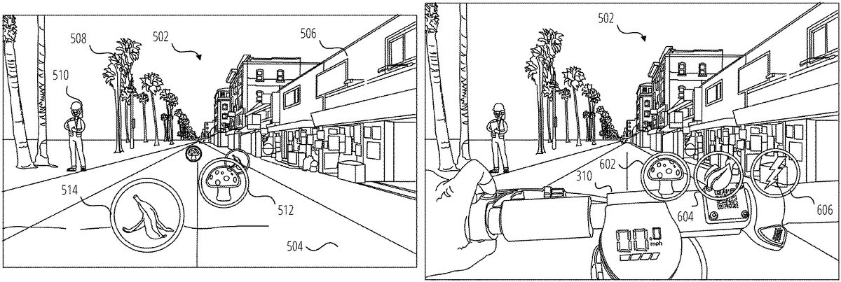
FIG.5is a view of an outdoor environment502that has been enhanced with AR elements that are displayed on the displays1516of the glasses100according to one example. In this example, a user is riding a scooter300along a street or pathway504in the environment502, which includes buildings506, trees508, people510and so forth. The pose of the glasses100relative to the environment502has been determined and is continually updated using known AR localization and tracking techniques, including for example by a visual processing technique such as Simultaneous Localization and Mapping (SLAM). The pose of the glasses100can be refined and the particular identity and characteristics of the environment can be further determined by comparing SLAM data with existing point cloud models for the environment502, stored in on a server410or downloaded to the glasses100, client device404or scooter300. Additionally, the location of the glasses100, scooter300or client device404can be determined from (IPS coordinates, or by these devices sharing location information with each other.
The pose of the glasses100permits virtual objects to be displayed to the user in the frame of reference of the environment. That is, a virtual object such as a power up512(illustrated as a mushroom) and a power down514(illustrated as a banana) can be displayed by the glasses100in a fixed position on the pathway504. As the user turns their head or approaches one of the virtual objects, its apparent position on the pathway504is maintained, with appropriate scaling as the user approaches or recedes from the virtual object. The positions of the virtual objects414can be predefined for a particular location (for example along a popular trail) or can be positioned intermittently by the AR application. In one example, the positions and identities of the virtual objects414are defined in a map of the environment that is stored on the client device404or on the server410and, which is or accessed by the AR application based on the pose and location of the glasses100. Similarly, the data defining individual virtual objects414including their appearance and performance-altering characteristics are stored in a database hosted on the server410or locally on the client device404.
Since the position of the user in the environment502is known (being the position of the scooter300, glasses100or client device404), and the positions of the virtual objects414in the environment502are known, the user can interact with the virtual objects by riding over or through them as perceived by the user. The effect of such an interaction will depend on the nature of the virtual object. For example, when the scooter300passes over (the location of) a power up512, the power of the scooter300that is available for use can be increased, or the maximum speed of the scooter can be increased, typically for a certain amount of time. Similarly, when the scooter300passes over a power down514, the power of the scooter300that is available for use can be decreased, or the maximum speed of the scooter can be decreased, typically for a certain amount of time or it can be brought completely to a halt. In this way, interaction with a virtual object can affect the behavior or characteristics of real devices such as the scooter300. It will of course be appreciated that the scooter300itself does not actually ride over the virtual object414, but rather the position of the scooter300at the perceived location of the virtual object414is detected by the glasses100, the client device404or the scooter300.
In another example, interaction with virtual object such as the power up512as shown inFIG.5, can result in the virtual object414being acquired by the user for use at a later time, in which case the virtual object may be transferred to and positioned in a frame of reference of the glasses100or the scooter300as described in more detail below with reference toFIG.6. In such a case, further interaction with the virtual object by the user is required to trigger the change in behavior or characteristics of the scooter300as discussed above. The user can thus acquire a power up512or other virtual object and choose to use it at a time of their choosing.
FIG.6is a view of the handlebars310of scooter300in an outdoor environment502, in which the scooter300has been enhanced with AR elements according to one example. In this case, virtual objects such as power up602, eco mode604and sport mode606are displayed to the user, by the glasses100, in the frame of reference of the scooter300. In this example, the virtual objects are shown as floating just above the handlebars310of the scooter300. As the user402turns their head or gets closer to or further from one of the virtual objects, its position on the handlebars310is maintained, with appropriate scaling as the user approaches or recedes from the virtual object.
The virtual objects illustrated inFIG.6may be persistent in the frame of reference of the scooter300, for example the eco mode604and sport mode606virtual objects may represent features or adjustments to the operation of the scooter that are available at all times during operation of the scooter300. In this way, the available control features of the scooter can be extended beyond those that are available using the physical controls on the scooter.
The virtual objects414illustrated inFIG.6may also appear and disappear during operation of the scooter, for example they may appear as they become available for use and may then disappear after use. In one case, when a scooter rides over a power up512as shown inFIG.5, it will disappear from the pathway504and appear as the power up602in the frame of reference of the scooter300as shown inFIG.6. This can occur when the performance-modifying effect of the power up512does not occur immediately when the scooter300arrives at the position in the real world corresponding to the location of the power up512but is rather delayed until such time as the user decides to activate it as discussed below. The power up512has effectively been acquired rather than activated by passage of the scooter300.
To facilitate positioning of the virtual objects414inFIG.6. The handlebars310are detected by the glasses100or the client device404within the field of view of the cameras132of the glasses100using object detection techniques applied to a video feed from the cameras132. Using 3D reconstruction techniques, the relative position and orientation between the glasses100and the handlebars310can be determined by the glasses100or the client device404, permitting the correct placement of the virtual objects above the handlebars310as the relative position between the handlebars310and the glasses100change due to user or handlebar movement.
In another example, the relative position and orientation of the scooter300and the glasses100can be determined by comparing their individual poses in a common local or global frame of reference. In such a case it will be necessary for the scooter300to provide data relating to an angle through which the handlebars are turned in order to fix the virtual objects to the handlebars310in the user's field of view. Alternatively, the virtual objects could be fixed with reference to the main body302or steering column304, to float in a fixed orientation above the handlebars310or (other portion of a personal mobility system) regardless of the orientation of the handlebars310.
In use of the example shown inFIG.6, the intersection of a user's hand or finger(s) with one of the virtual objects (power up512, eco mode604, sport mode606) is detected in the video feed from one or both of the cameras132using gesture detection or other visual object intersection techniques. In response to such detection, an instruction is provided by the glasses100or the client device404to modify the behavior of the scooter300appropriately based on the particular virtual object with which the user has interacted.
FIG.7is a view of an outdoor environment702that has been enhanced with AR elements that are displayed on the displays1516of the glasses100according to one example. As before, a user is riding a scooter300through the outdoor environment702. The pose of the glasses100relative to the environment702has been determined and is continually updated using known AR localization and tracking techniques, including for example by a visual processing technique such as Simultaneous Localization and Mapping (SLAM). The pose of the glasses100can be refined and the particular identity and characteristics of the environment can be further determined by comparing SLAM data with existing point cloud models for the environment702, stored in on a server410or downloaded to the glasses100, client device404or scooter300. Additionally, the location of the glasses100, scooter300or client device404can be determined from GPS coordinates, or by these devices sharing location information with each other.
In this example, the environment702includes a walking path704, a bicycle path706a street710and a traffic cone712located on the bicycle path706to indicate a hazard in the bicycle path706. Personal mobility systems are not permitted on the walking path704but only on the bicycle path706in this example. To assist the user with navigating the environment, one or more virtual objects414are placed in the user's field of view as displayed by the glasses100. In this example, a colored AR overlay708is positioned over the bicycle path706to highlight the path that the user is permitted to take, thereby facilitating correct riding etiquette. Alternatively, forbidden areas (such as the walking path704) or more hazardous areas (such as a street710with cars) can be provided with an overlay instead of or in addition to the AR overlay708on the706. Different colors or effects may be used to distinguish the correct path or area that can be traversed by the scooter300from forbidden or hazardous areas.
As with the examples discussed above, interaction with the AR overlay708by proximity of the scooter300to the location in the environment of the AR overlay708can affect the behavior and character of the scooter. In the case of the AR overlay708, positioning of the scooter on the bicycle path706(that is on the AR overlay708as perceived by the user) can enable operation at the full capability of the scooter300, while departing from the bicycle path706(or from the AR overlay708as perceived by the user) can result in reduced functioning of the scooter300. Additional effects may also be provided to prompt the user to use the correct path, for example by changing the color or other effects (for example flashing or pulsing) of the AR overlay708as displayed by the glasses100when the scooter leaves the bicycle path706. Alternatively, if overlays or other virtual objects414are provided on the walking path704or the street710, positioning of the scooter300on the overlay or intersecting with the virtual object can trigger reduced functioning of the scooter300, which is unchanged when the scooter300is positioned on the bicycle path706.
The AR application running on either the glasses100or client device404may also scan for relevant physical objects or features in the environment702using known object detection and recognition techniques. For example inFIG.7, the traffic cone712, which is an indicator that a hazard may be present in the bicycle path706, can be detected by the glasses100or client device404. A virtual object414can then be displayed by the glasses100to highlight the traffic cone. For example, a pulsing or flashing high-contrast AR overlay can be placed on or around the traffic cone712in the scene as viewed by the user through the glasses100.
Any physical object406that is a hazard, identifies a hazard, or provides other relevant information to a rider of a personal mobility system can be highlight in this manner, including crosswalks, signage, caution tape, and so forth.
In addition to emphasizing the physical object, the behavior of the personal mobility system can be altered in response to proximity with the hazard. For example, the brakes could be applied or the maximum speed or power could be reduced as before as the user402approaches the hazard.
FIG.8is a view of an outdoor environment802that has been enhanced with AR elements that are displayed on the displays1516of the glasses100according to another example. As before, a user is riding a scooter300through the outdoor environment802. Also as before, the environment802includes a walking path704, a bicycle path706and a street710. As for environment702discussed with reference toFIG.7, AR overlay708has been provided to highlight the bicycle path706.
In this example, the AR application running on either the glasses100or client device404has detected an otherwise unmarked hazard (a pothole804) in the environment702using known object detection and recognition techniques. In one example, the object detection and recognition is performed using a context or location-specific model for potential obstacles or objects that is loaded into the memory of the glasses100or client device404. This reduces the data processing burden since the glasses100or client device404need only search for potential obstacles or warning signs that may be present in that context or at that location. For example, the context-specific ML model will not include road signs if the user402is riding on a mountain bike trail.
In the example ofFIG.8, in response to detecting the pothole804, a virtual traffic cone806is displayed by the glasses100at the perceived location of the pothole804in the field of view of the glasses100. Various effects can be applied. For example, a pulsing or flashing high-contrast AR overlay can be placed on or around the virtual traffic cone806in the scene as viewed by the user through the glasses100.
Any physical object406that is a hazard, identifies a hazard, or provides other relevant information to a rider of a personal mobility system can be highlight in this manner, including crosswalks, signage, potholes, sinkholes, trenches, ditches and so forth. Other virtual signage, such as a sign with “DANGER AHEAD,” can be placed over or in front of a physical hazard such as the pothole804in the field of view of the glasses100, in addition to or instead of the virtual traffic cone806.
In addition to emphasizing the physical object, the behavior of the personal mobility system can be altered in response to proximity with the pothole804. For example, the brakes could be applied or the maximum speed or power could be reduced as before.
FIG.9is a view of an outdoor environment902that has been enhanced with AR elements that are displayed on the displays1516of the glasses100according to another example. As before, a user is riding a scooter300through the outdoor environment902. In this case, the user is riding collaboratively or competitively with a friend906on another scooter908. The user and the friend are riding along a pathway904on a shared virtual race course that has been defined along the pathway904.
The AR elements shown on the user's display include items that are unique to the user as well as items that are common to those displayed on a corresponding AR device (such as glasses100) worn by the friend906. In the illustrated embodiment, a power down910and a virtual finish line914are or can be seen by both the user and the friend906(depending on where they are looking, that is where their glasses100are pointing), with appropriate adjustments to size, location and orientation in the field of view of the glasses100of both the friend906and the user. That is, these objects are, from the perspective of both participants, located in the same physical location in the real world but in different locations in the frame of reference of their respective glasses100. Additional virtual objects or AR elements can be displayed as shared, including for example indicators of the race course surface (such as an AR overlay708as shown inFIG.7) or track borders or directional arrows shown to illustrate the course to the user and the friend906.
The AR elements shown on the user's display that are unique to the user may for example include status information912, which may be fixed at the top left of the field of view of the glasses100, and AR effects such as a virtual plume916that appears to be emanating from the rear of the friend's scooter908. The virtual plume916may vary in color or appearance to distinguish between different participants. The status information912may be included in each participant's display, appropriately modified for that participant. As shown, the status information912can include an elapsed time and the user's position (2nd Place) in the race, lap time, finish time and position (once the virtual finish line914is crossed), points accrued, a race and season leader board, information about other participants such as ranking, username, riding level, and so forth.
In use, the course is accessed by the participants in a shared session in which they can, for example, race against each other. The session can be scheduled and created using a messaging or social media application running on participants' client devices404or glasses100. Shared sessions can be by invitation or advertised as available based on proximity of the user's friends (as represented by the proximity of their respective client devices404or glasses100) to the start point. Virtual objects414such as power ups512and power downs514are available to the participants for interaction as discussed above, and intersection or proximity to a virtual object414will similarly affect each user's scooter as discussed above, to provide a boost or handicap or other effect depending on the virtual object. Virtual objects414can include start/stop designators, navigational cues, real-world object warnings, a virtual value object (e.g., coins or upgrades that increase or decrease a score), or performance modifying objects, and so forth.
Virtual objects414can be persistent (that is, they remain available to other participants even when one participant has used or acquired a virtual object) or they can vanish from the course for other participants once one participant has acquired or used it. Additionally, virtual objects414could respawn after a certain amount of time, or for each lap of the course, depending on their properties. Furthermore, some virtual objects414can be acquired for later use as described with reference toFIG.6. Users can ride through previously created tracks on their own or with other users at the same time. Metrics (e.g., scores or lap times) are then shared between participants within the multiplayer environment and they are ranked accordingly. In an example, when two users are competing in the same course at the same time, the AR device can display information about other players (e.g., ranking, username, riding level). In this example, standard localization methods (e.g., GPS) or the localization/detection methods described in can be used to generate and display information about other riders during competition.
FIG.10illustrates a user interface1002for an environment building mode according to one example. The user interface1002includes a map1004with roads1006or other geographical features and a menu1008. The user interface1002is displayed on the display of a computing device such as client device404, glasses100, a tablet or laptop computer and so forth. The menu1008includes options for creating a new course, saving a course that is being or has been created, an undo feature to reverse the last editing action and a share feature. Additional editing features may be provided.
The map1004may be displayed based on the proximity of the computing device or may be a location that has been found or specified by the user by searching for or entering a specific location. The user interface1002permits a user to creates a virtual track or course, fixed relative to the real world, and including virtual objects as discussed above. This course can then be ridden by one or more users in a competitive or recreational or collaborative gameplay mode as discussed above.
FIG.11illustrates the user interface ofFIG.10in which a course has or is being created. The user interface1102shows a course1104with a starting line1106and a finish lines1108. In one example, a user first creates the course (e.g., a continuous path or a series of waypoints) by physically riding through the desired course while wearing the glasses100. In this example, the user interface1102in response to receiving a “New” input provides an option to “Record New Course.” In response to receiving selection of this option by the user, the glasses100or client device404captures a sequence of location information corresponding to the position of the glasses100, client device404or scooter300until a “Stop Recording” input is received from the user. The course is then defined with the starting line1106being when the “Record New Course” input was received and with the finish line1108being when the “Stop Recording” input is received and the track of the course being defined by the sequence of captured location information.
In addition to recording the basic path taken by the scooter while capturing the location information, the glasses100may perform object recognition or 3D reconstruction to detect relevant boundaries for defining the course, for example the edges of a path or a road on which scooter is riding. The course can then be defined by such boundaries rather than just by the track of the scooter. Similarly, the recorded track can be compared by one of the computing devices in the system (such as client device404or server410and so forth) with the boundaries of known routes (paths, roads and so forth) along the recorded path. The boundaries of the course can then be set by the relevant computing device as the boundary of the corresponding route.
In another example, the course is created in response to user inputs on the user interface1102. For example, in response to receiving a “New” input in the user interface1002, sequential touch inputs could be received on a display with a touchpad (such as on client device404) to define the starting line1106, turns and finish line1108. Various editing options could be provided, for example to move a turning point by pressing, holding and dragging it, by receiving “Undo” commands, and so forth.
Also illustrated in user interface1102is a “+ Item” menu option1110, which can be used to add virtual objects or other information to the course1104.
FIG.12illustrates the user interface ofFIG.10in which virtual objects414are being placed on a course that is being or has been defined as described with reference toFIG.11. The user interface1202is displayed in response to receiving selection of the “±Item” menu option1110shown inFIG.11. As can be seen, the user interface1202includes a number of available virtual objects1206, which can be dragged and dropped from the menu1210onto the course1104, which is illustrated inFIG.12by course boundaries1204. Placed virtual objects1208are shown in the user interface1202, which can be moved by drag inputs or deleted in response to a long press on a placed available virtual object1206followed by selection or confirmation of a delete option. In response to receiving an input on “Done” menu option1212, the display will revert to user interface1102.
When the course1104has been finalized, upon receipt of a Save or Share input, the corresponding action is taken. In one example, the course may be shared via a message composed in a chat interface of a messaging application and sent to one or more of a user's connections or friends. The Share message may include an invitation to ride the course, as well as time, date and location information and an RSVP option.
FIG.13is a flowchart1300showing operation of the network environment400, according to one example. In this example, two or more participants are going to compete against each other on a course that has been defined as described with reference toFIG.10toFIG.12andFIG.14.
The operations illustrated inFIG.13will typically execute on a combination of client device404and glasses100, although the operations may execute exclusively in glasses100or in a combination of the glasses100and one or all of client device404, scooter300and server410. In the case of a collaborative or competitive session as contemplated, the operations inFIG.13will execute on each user's devices. Various implementations are of course possible. In one example, the operations are performed jointly between the glasses100, which provides a video feed for processing from at least one of its cameras132and positional information from its IMU and GPS receiver to an AR application running on the client device404, which processes the video feed, performs any required 3D reconstruction and tracking, and generates and transmits AR effects, including virtual objects414, to the glasses100for display to the user402. For the purposes of clarity, flowchart1300is discussed herein with reference to such an example.
Prior to the commencement of the flowchart1300, localization and tracking of the glasses100has commenced and is ongoing for all participants. The pose of the glasses100and their location in the environment502is thus known to the glasses100and the AR application running on the corresponding client device404. Additionally, if required, the locations and poses of related devices such as the scooter300or client device404are determined and communicated as needed between the glasses100, scooter300and client device404for a particular participant.
A map of the environment, including the location of the virtual objects414and the course1104, has been downloaded or is available for download to the participants' client devices from server410. In the case of detection of hazards (including identifiers of hazards), such as inFIG.7orFIG.8, each client device404has been and continues to perform object detection and recognition techniques to identify and locate hazards within the field of view of the glasses100. Once a hazard has been identified, a corresponding virtual object414is placed in a map of the environment or in a corresponding location in a frame of reference of the glasses100.
The method starts at operation1302with the initiation of a joint session involving all of the participants. The joint session may be initiated in response to an invitation transmitted by one of the participants from their client device404to their friends or connections, or may be in response to a prompt that is triggered upon the detection of the proximity between the client devices404or glasses100of users402who are friends or connections to each other and are either at or near enough to the location of the start course1104to be able to join in a reasonable time.
The method continues at operation1304with a determination of and comparison between the locations and poses of the devices (scooter300, glasses100or client device404) for the participants in the joint session. The purpose of this comparison is three-fold. Firstly, to locate each participant on the course, secondly, (in subsequent iterations of the method) to determine the relative positions of the participants on the leaderboard, and thirdly, to identify the relative positions of the scooters300and their riders to permit AR effects to be applied to scooters300or participants within the field of view of a particular participant. The location of any of the devices (glasses100, scooter300or client device404) can be used as a proxy for the location of its user for many purposes in the method, since they will essentially be collocated with the particular user402at all relevant times.
At operation1306, the status information912and AR effects (such as virtual plume916) are applied, updated and displayed by the glasses100for each participant. In some cases AR effects are applied based on the relative poses between scooters300as determined by measurements from position components1708(GPS receivers, inertial measurement units and so forth) and in some cases by object recognition performed by the glasses100or client device404to identify participants or scooters in the field of view of a particular pair of glasses100.
The method continues at operation1308with a comparison between the location and field of view of the glasses100of each participant and the locations of any nearby virtual objects414. The purpose of this comparison is two-fold. Firstly, to display any visible virtual objects414in the displays of the glasses100, fixed to an appropriate frame of reference (e.g., a global real world frame of reference as shown inFIG.7or to a local frame of references such as the scooter300as shown inFIG.6) and to determine any intersection of or proximity between a user402and a virtual object414fixed in the real world frame of reference, such as power down514or power up512.
In operation1324any visible virtual objects414(such as power down910, power up512, a starting line1106and so forth) are rendered by the glasses100using conventional AR techniques. In some instances, nearby virtual objects in the line of sight of the glasses100may, not be visible due to an intervening virtual object or physical object as determined by a 3D model of the environment, for example based on an existing 3D point cloud model of the area or 3D reconstruction techniques performed by the glasses100or client device404on the video feed from the cameras132. From operation1324the method returns to operation1304and this loop continues repetitively to ensure that any movement by the user (as reflected by movement of one or more of the glasses100, scooter300and client device404) and the appearances of new or current virtual objects414in the field of view of the user402are correctly displayed to the user402by the glasses100, that status information912is updated for each participant, and that any AR effects are correctly rendered.
The display of virtual objects in operation1324includes the display over the environment802of the boundaries1204of the course, an AR overlay708indicating the course or off-limits areas, a virtual starting line, virtual finish line914and any directional indicators such as arrows displayed on or over the pathway904to indicate turns and course direction. Individual scoring, position and timing information will also be displayed by the glasses100to each user402, such as status information912as described with reference to operation1306. In response to user input initiating the race, received from the organizer of the joint session, the status information912may provide a visual or audible countdown to race start to the participants via the glasses100. Upon commencement of the race, the loop in the flowchart between operation1324and operation1304continues with appropriate updates as the race progresses.
From operation1308, the method also proceeds to operation1310where it is determined whether the location of a user402(or a part of the user402) is proximate to a virtual object414during the race. This can be as a result of the glasses100, scooter300or client device404arriving at the location in the real world of the virtual object414or by visually detecting intersection of a hand or other body part of the user402with the virtual object414. How close the user402and the virtual object414need to be to satisfy this test will depend on the particular virtual object and the associated implementation. For a power up512or a power down514, the proximity will be sufficiently close as to make the user402and the virtual object414essentially collocated. For a virtual object that will trigger a warning or a change in performance characteristics such as a virtual traffic cone, or arrival on or departure from AR overlay708, the proximity may be appropriately greater so as to provide sufficient warning before the scooter actually arrives at the hazard or departs from an authorized path. Sufficient proximity to satisfy the test for a particular virtual object can be considered to be intersection with the virtual object.
If no intersection is detected in operation1310, the method returns to operation1304and continues from there. If intersection is detected in operation1310, the virtual object414is updated if appropriate at operation1312. For example, a power up512or power down514may disappear from its apparent location and thus be unavailable for re-use by the user402or other riders or it may be persistent and available for re-use as discussed above. The disappearance may be temporary or until the course is restarted. On the other hand, an object such as a virtual traffic cone or an AR overlay708is likely to be persistent.
The method then proceeds to operation1314where the parameters associated with the virtual object414are processed to determine the appropriate actions to be taken by the glasses100or client device404for the participant who has interacted with the virtual object414. The actions taken in response to intersection with the virtual object414will depend on the particular characteristics of the virtual object414. The parameters associated with the virtual object will define whether there are any sounds or visuals associated with intersection with the virtual object414, the nature and extent of the associated change in the available or current performance characteristics of the scooter300(or other personal mobility system), the duration of the change in the performance characteristics (permanently, for a certain amount of time, for as long as the scooter300is sufficiently proximate to the location of the virtual object414and so forth), and the timing of the change (immediate, delayed, delayed until activated by the user402, delayed until another condition is met, and so forth.) Additionally, if the virtual object414has an associated score value (increase or decrease), the user's score is adjusted accordingly and the status information912updated. In the case of a race, crossing the virtual finish line914will end the race (and the flowchart1300) and the status information912will show a final time, score and race position as appropriate.
For virtual objects414that are associated with an immediate change in the performance, the method proceeds at operation1316, where an instruction or signal is transmitted to the scooter300from the client device404or the glasses100to alter the performance characteristics of the scooter300according to the characteristics of the virtual object414. The method then returns to operation1304and proceeds from there.
For virtual objects414that are associated with a delayed or selectable change in performance, the method proceeds at operation1318, where the virtual object is transferred to a new location, typically in a local frame of reference of the glasses100or scooter300as described above with reference toFIG.6for example, where an input can be received from a user402to activate the performance altering characteristics corresponding to the virtual object414at a time of the user's choosing. The user has thus effectively acquired the virtual object414.
Upon receipt of selection of the virtual object in operation1320(for example as discussed above with reference toFIG.6), an instruction or signal is transmitted to the scooter300from the client device404or the glasses100in operation1322to alter the performance characteristics of the scooter300according to the characteristics of the virtual object414. The method then returns to operation1304and proceeds from there.
Once commenced, the operations of flowchart1300will continue for each participant with the display of information and virtual objects414continuing as discussed above with reference toFIG.5toFIG.9continuing until the participant crosses the finish line1108as determined by one or more of their client device404, glasses100or scooter300comparing its location to the location of the finish line.
As the participants cross the finish line, the status information912is updated for each participant, to show their finishing position, finishing time, score, and any related or derived information, such as an event or season leaderboard. Additional AR effects, such as streamers or fireworks could also be provided. Each participant is then able to share their results, screen shots, video recordings, and so forth, via a messaging application1608or social media application within which the method runs or is associated.
FIG.14is a flowchart1400showing course generation, according to one example. The operations illustrated inFIG.13will typically execute on a combination of client device404and glasses100, although the operations may execute exclusively in client device404or in a combination of the client device404and one or all of glasses100, scooter300and server410. For clarity, the flowchart is described in this example as executing on a client device404.
The flowchart1400commences with receipt by the client device404of an input to generate a course at operation1402. This may for example be the selection of a dedicated application on the client device, or the selection of the course generation feature from within a messaging or social media or other application. In response to this selection, various options for course generation will be displayed in a user interface on the client device, including options for manual or automatic course generation.
In response to receiving a manual course generation input at operation1404, the client device404displays the user interfaces1002ofFIG.10with a map1004that is initially based on the location of the client device404, but which can be panned to a new location, or the location can be altered in response to search input provided by the user. At operation1408, the client device404(via the relevant application) receives course creation input as discussed above with reference toFIG.10andFIG.11to create the course. Course editing input is then received in operation1410to edit, modify or add features as discussed above with reference toFIG.11andFIG.12.
In response to receiving a “record course” input at operation1404, the client device404displays a user interface with a “Start Recording” prompt. A user interface for course recording is likely to be displayed on the glasses100instead of or in addition to on the client device404for more convenient user input while riding the course.
At operation1406, the glasses100or client device404(via the relevant application) receives user input to begin recording the course, for example by a tap input on a touchpad of the glasses100or by voice input. The glasses100or client device404then captures the initial location of the glasses100, client device404or scooter300in operation1412. Location information is provided by relevant hardware in the relevant device, including for example position components1708and motion components1706(seeFIG.17), such as a GPS receiver. The initial location is marked as the location of the start of the course. The user402then proceeds to ride the intended course and a “Stop Recording” prompt is displayed, again likely on the glasses100instead of or in addition to the client device404.
If a “Stop Recording” input is not received at operation1414, the glasses or client device continues to capture the location of the glasses100, client device404or scooter300until a “Stop Recording” input is received. The location at which this input is received is then marked as the finish line of the course, and the course is generated by the client device in operation1416from the sequence of locations captured by the glasses100or client device404during recording. The user interface1102ofFIG.11is then displayed and course editing input is then received in operation1418to edit, modify or add features as discussed above with reference toFIG.11andFIG.12.
After the completion of any course editing in operation1410or operation1418, the client device404receives input in operation1420to save, share or delete the course, and takes the corresponding action in response to received input.
FIG.15is a block diagram1500illustrating a networked device1502including details of the glasses100and the scooter300, in accordance with some examples.
The networked device1502(e.g., glasses100, scooter300, client device404) is communicatively coupled to at least one second networked device1504and a server system1508. The distinction between the networked device1502and the second networked device1504is made only for purpose of differentiating between two distinct devices. It should be understood that the description made herein with respect to the networked device1502describes in equal measure the second networked device1504.
The networked device1502is capable of communicatively coupling with the second networked device1504using both a low-power wireless connection1510and a high-speed wireless connection11512. The second networked device1504is connected to the server system1508via the network1506. The network1506may include any combination of wired and wireless connections. The server system1508may be one or more computing devices as part of a service or network computing system. The second networked device1504and any elements of the server system1508and network1506may be implemented using details of the software architecture1602or the machine1700described inFIG.16andFIG.17.
The networked device1502may include a data processor1514, displays1516, one or more cameras1518, input/output elements1520, and additional sensors1522. The input/output elements1520may include microphones, audio speakers, biometric sensors, or additional display elements (e.g., Visual feedback element332) integrated with the data processor1511. In some implementations, input/output elements1520such as speakers, horns, haptic generators, displays and head lights/signal/telltale lights all are used to cue the user of a networked device1502of safety issues, warn the rider visually, aurally, or haptic notice of a safety issue. Examples of input/output elements1520are discussed further with respect toFIG.16andFIG.17. For example, the input/output elements1520may include any of I/O components1702including output components1704, motion components1706, and so forth. Examples of the displays1516are discussed inFIG.1andFIG.2. In the particular examples described herein, the displays1516include a display for each one of a user's left and right eyes.
Sensors1522may include optical sensors (e.g., photoresistors, lidar, infrared), radio frequency sensors (e.g., radar), mechanical wave sensors (e.g., sonar, pressure), and inertial sensors (e.g., accelerometers, gyroscopes, magnetometers). The networked device1502may use some or all of the foregoing in order to detect physical objects or determine a position or pose of the networked device1502. For example, inertial sensors may provide information on the roll, yaw, and pitch of the networked device1502. The networked device1502may use this information to detect and notify the user of accidents or other impacts, detect uphill travel to increase power to a propulsion source (e.g., propulsion source322), or detect downhill travel to establish system braking or power recovery to keep the networked device1502(or the second networked device1504) from exceeding safe speeds and accelerations. Integration with accelerometer/speedometer data also provides significant data for the networked device1502to detect, intervene if necessary, and transmit instructions to drive propulsion (e.g., by the management system324to the propulsion source322) and braking performance.
The data processor1514includes an image processor1524(e.g., a video processor), a GPU & display driver1526, a tracking module1528, low-power circuitry1530, and high-speed circuitry1532. The components of the data processor1514are interconnected by a bus1534.
The data processor1514also includes an interface1536. The interface1536refers to any source of a user command that is provided to the data processor1514. In one or more examples, the interface1536is a physical button that, when depressed, sends a user input signal from the interface1536to a low-power processor1538. A depression of such button followed by an immediate release may be processed by the low-power processor1538as a request to capture a single image, or vice versa. A depression of such a button for a first period of time may be processed by the low-power processor1538as a request to capture video data while the button is depressed, and to cease video capture when the button is released, with the video captured while the button was depressed stored as a single video file. Alternatively, depression of a button for an extended period of time may capture a still image. In other examples, the interface1536may be any mechanical switch or physical interface capable of accepting user inputs associated with a request for data from the cameras1518. In other examples, the interface1536may have a software component, or may be associated with a command received wirelessly from another source, such as from the client device404.
The image processor1524includes circuitry to receive signals from the cameras1518and process those signals from the cameras1518into a format suitable for storage in the memory1544or for transmission to the client device404. In one or more examples, the image processor1524(e.g., video processor) comprises a microprocessor integrated circuit (IC) customized for processing sensor data from the cameras1518, along with volatile memory used by the microprocessor in operation.
The low-power circuitry1530includes the low-power processor1538and the low-power wireless circuitry1540. These elements of the low-power circuitry1530may be implemented as separate elements or may be implemented on a single IC as part of a system on a single chip. The low-power processor1538includes logic for managing the other elements of the networked device1502. As described above, for example, the low-power processor1538may accept user input signals from the interface1536. The low-power processor1538may also be configured to receive input signals or instruction communications from the client device404via the low-power wireless connection1510. The low-power wireless circuitry1540includes circuit elements for implementing a low-power wireless communication system. Bluetooth™ Smart, also known as Bluetooth™ low energy, is one standard implementation of a low power wireless communication system that may be used to implement the low-power wireless circuitry1540. In other examples, other low power communication systems may be used.
The high-speed circuitry1532includes a high-speed processor1542, a memory1544, and a high-speed wireless circuitry1546. The high-speed processor1542may be any processor capable of managing high-speed communications and operation of any general computing system needed for the data processor1514. The high-speed processor1542includes processing resources needed for managing high-speed data transfers on the high-speed wireless connection1512using the high-speed wireless circuitry1546. In certain examples, the high-speed processor1542executes an operating system such as a LINUX operating system or other such operating system such as the operating system1604ofFIG.16. In addition to any other responsibilities, the high-speed processor1542executing a software architecture for the data processor1514is used to manage data transfers with the high-speed wireless circuitry1546. In certain examples, the high-speed wireless circuitry1546is configured to implement Institute of Electrical and Electronic Engineers (WEE) 802.11 communication standards, also referred to herein as Wi-Fi. In other examples, other high-speed communications standards may be implemented by the high-speed wireless circuitry1546.
The memory1544includes any storage device capable of storing camera data generated by the cameras1518and the image processor1524. While the memory1544is shown as integrated with the high-speed circuitry1532, in other examples, the memory1544may be an independent standalone element of the data processor1514. In certain such examples, electrical routing lines may provide a connection through a chip that includes the high-speed processor1542from image processor1524or the low-power processor1538to the memory1544. In other examples, the high-speed processor1542may manage addressing of the memory1544such that the low-power processor1538will boot the high-speed processor1542any time that a read or write operation involving the memory1544is needed.
The tracking module1528estimates a pose of the networked device1502. For example, the tracking module1528uses image data and corresponding inertial data from the cameras1518and the position components1708, as well as GPS data, to track a location and determine a pose of the networked device1502relative to a frame of reference (e.g., real-world environment). The tracking module1528continually gathers and uses updated sensor data describing movements of the networked device1502to determine updated three-dimensional poses of the networked device1502that indicate changes in the relative position and orientation relative to physical objects in the real-world environment.
In the glasses100implementation of the networked device1502, the tracking module1528permits visual placement of virtual objects relative to physical objects by the networked device1502within the field of view of the user via the displays1516. The GPU & display driver1526may use the pose of the networked device1502or the second networked device1504to generate frames of virtual content or other content to be presented on the displays1516when the networked device1502is functioning in a traditional augmented reality mode. In this mode, the GPU & display driver1526generates updated frames of virtual content based on updated three-dimensional poses of the networked device1502and/or the second networked device1504, which reflect changes in the position and orientation of the user in relation to physical objects in the user's real-world environment.
One or more functions or operations described herein may also be performed in an application resident on the networked device1502, on the second networked device1504, or a server system1508. For example, one or more functions or operations described herein may be performed by one of the applications1606such as messaging application1608.
FIG.16is a block diagram1600illustrating a software architecture1602, which can be installed on any one or more of the devices described herein. The software architecture1602is supported by hardware such as a machine1610that includes processors1612, memory1614, and I/O components1616. In this example, the software architecture1602can be conceptualized as a stack of layers, where each layer provides a particular functionality. The software architecture1602includes layers such as an operating system1604, libraries1618, frameworks1620, and applications1606. Operationally, the applications1606invoke API calls1622through the software stack and receive messages1624in response to the API calls1622.
The operating system1604manages hardware resources and provides common services. The operating system1604includes, for example, a kernel1626, services1628, and drivers1630. The kernel1626acts as an abstraction layer between the hardware and the other software layers. For example, the kernel1626provides memory management, processor management (e.g., scheduling), component management, networking, and security settings, among other functionalities. The services1628can provide other common services for the other software layers. The drivers1630are responsible for controlling or interfacing with the underlying hardware. For instance, the drivers1630can include display drivers, camera drivers, BLUETOOTH® or BLUETOOTH® Low Energy drivers, flash memory drivers, serial communication drivers (e.g., Universal Serial Bus (USB) drivers), WI-FI® drivers, audio drivers, power management drivers, and so forth.
The libraries1618provide a low-level common infrastructure used by the applications1606. The libraries1618can include system libraries1632(e.g., C standard library) that provide functions such as memory allocation functions, string manipulation functions, mathematic functions, and the like. In addition, the libraries1618can include API libraries1634such as media libraries (e.g., libraries to support presentation and manipulation of various media formats such as Moving Picture Experts Group-4 (MPEG4), Advanced Video Coding (H.264 or AVC), Moving Picture Experts Group Layer-3 (MP3), Advanced Audio Coding (AAC), Adaptive Multi-Rate (AMR) audio codec, Joint Photographic Experts Group (JPEG or JPG), or Portable Network Graphics (PNG)), graphics libraries (e.g., an OpenGL framework used to render in two dimensions (2D) and three dimensions (3D) in a graphic content on a display), database libraries (e.g., SQLite to provide various relational database functions), web libraries (e.g., WebKit to provide web browsing functionality), and the like. The libraries1618can also include a wide variety of other libraries1636to provide many other APIs to the applications1606.
The frameworks1620provide a high-level common infrastructure that is used by the applications1606. For example, the frameworks1620provide various graphical user interface (GUI) functions, high-level resource management, and high-level location services. The frameworks1620can provide a broad spectrum of other APIs that can be used by the applications1606, some of which may be specific to a particular operating system or platform.
In an example, the applications1606may include a home application1638, a contacts application1640, a browser application1642, a book reader application1644, a location application1646, a media application1648, a messaging application1608, a game application1650, and a broad assortment of other applications such as third-party applications1652. The applications1606are programs that execute functions defined in the programs. Various programming languages can be employed to create one or more of the applications1606, structured in a variety of manners, such as object-oriented programming languages (e.g., Objective-C, Java, or C++) or procedural programming languages (e.g., C or assembly, language). In a specific example, the third-party applications1652(e.g., applications developed using the ANDROID™ or IOS™ software development kit (SDK) by an entity other than the vendor of the particular platform) may be mobile software running on a mobile operating system such as IOS™ ANDROID™, WINDOWS® Phone, or another mobile operating system. In this example, the third-party applications1652can invoke the API calls1622provided by the operating system1604to facilitate functionality described herein.
FIG.17is a diagrammatic representation of a machine1700within which instructions1710(e.g., software, a program, an application, an applet, an app, or other executable code) for causing the machine1700to perform any one or more of the methodologies discussed herein may be executed. For example, the instructions1710may cause the machine1700to execute any one or more of the methods described herein. The instructions1710transform the general, non-programmed machine1700into a particular machine1700programmed to carry out the described and illustrated functions in the manner described. The machine1700may operate as a standalone device or may be coupled (e.g., networked) to other machines. In a networked deployment, the machine1700may operate in the capacity of a server machine or a client machine in a server-client network environment, or as a peer machine in a peer-to-peer (or distributed) network environment. The machine1700may comprise, but not be limited to, a server computer, a client computer, a personal computer (PC), a tablet computer, a laptop computer, a netbook, a set-top box (SIB), a PDA, an entertainment media system, a cellular telephone, a smart phone, a mobile device, a AR wearable device (e.g., a smart watch), a smart home device (e.g., a smart appliance), other smart devices, a web appliance, a network router, a network switch, a network bridge, or any machine capable of executing the instructions1710, sequentially or otherwise, that specify actions to be taken by the machine1700. Further, while only a single machine1700is illustrated, the term “machine” shall also be taken to include a collection of machines that individually or jointly execute the instructions1710to perform any one or more of the methodologies discussed herein.
The machine1700may include processors1712, memory1714, and I/O components1702, which may be configured to communicate with each other via a bus1716. In an example, the processors1712(e.g., a Central Processing Unit (CPU), a Reduced Instruction Set Computing (RISC) processor, a Complex Instruction Set Computing (CISC) processor, a Graphics Processing Unit (GPU), a Digital Signal Processor (DSP), an ASIC, a Radio-Frequency Integrated Circuit (RFIC), another processor, or any suitable combination thereof) may include, for example, a processor1718and a processor1720that execute the instructions1710. The term “processor” is intended to include multi-core processors that may comprise two or more independent processors (sometimes referred to as “cores”) that may execute instructions contemporaneously. AlthoughFIG.17shows multiple processors1712, the machine1700may include a single processor with a single core, a single processor with multiple cores (e.g., a multi-core processor), multiple processors with a single core, multiple processors with multiples cores, or any combination thereof.
The memory1714includes a main memory1722, a static memory1724, and a storage unit1726, both accessible to the processors1712via the bus1716. The main memory1714, the static memory1724, and storage unit1726store the instructions1710embodying any one or more of the methodologies or functions described herein. The instructions1710may also reside, completely or partially, within the main memory1722, within the static memory1724, within machine-readable medium1728within the storage unit1726, within at least one of the processors1712(e.g., within the processor's cache memory), or any suitable combination thereof, during execution thereof by the networked device1502.
The I/O components1702may include a wide variety of components to receive input, provide output, produce output, transmit information, exchange information, capture measurements, and so on. The specific I/O components1702that are included in a particular machine will depend on the type of machine. For example, portable machines such as mobile phones may include a touch input device or other such input mechanisms, while a headless server machine will likely not include such a touch input device. It will be appreciated that the I/O components1702may include many other components that are not shown inFIG.17. In various examples, the I/O components1702may include output components1704and input components1730. The output components1704may include visual components (e.g., a display such as a plasma display panel (PDP), a light emitting diode (LED) display, a liquid crystal display (LCD), a projector, or a cathode ray tube (CRT)), acoustic components (e.g., speakers), haptic components (e.g., a vibratory motor, resistance mechanisms), other signal generators, and so forth. The input components1730may include alphanumeric input components (e.g., a keyboard, a touch screen configured to receive alphanumeric input, a photo-optical keyboard, or other alphanumeric input components), point-based input components (e.g., a mouse, a touchpad, a trackball, a joystick, a motion sensor, or another pointing instrument), tactile input components (e.g., a physical button, a touch screen that provides location and/or force of touches or touch gestures, or other tactile input components), audio input components (e.g., a microphone), and the like.
In further examples, the I/O components1702may include biometric components1732, motion components1706, environmental components1734, or position components1708, among a wide array of other components. For example, the biometric components1732include components to detect expressions (e.g., hand expressions, facial expressions, vocal expressions, body gestures, or eye tracking), measure bio-signals (e.g., blood pressure, heart rate, body temperature, perspiration, or brain waves), identify a person (e.g., voice identification, retinal identification, facial identification, fingerprint identification, or electroencephalogram-based identification), and the like. The motion components1706include acceleration sensor components (e.g., accelerometer), gravitation sensor components, rotation sensor components (e.g., gyroscope), and so forth. The environmental components1734include, for example, illumination sensor components (e.g., photometer), temperature sensor components (e.g., one or more thermometers that detect ambient temperature), humidity, sensor components, pressure sensor components (e.g., barometer), acoustic sensor components (e.g., one or more microphones that detect background noise), proximity sensor components (e.g., infrared sensors that detect nearby objects), gas sensors (e.g., gas detection sensors to detection concentrations of hazardous gases for safety or to measure pollutants in the atmosphere), or other components that may provide indications, measurements, or signals corresponding to a surrounding physical environment. The position components1708include location sensor components (e.g., a GPS receiver component), altitude sensor components (e.g., altimeters or barometers that detect air pressure from which altitude may be derived), orientation sensor components (e.g., magnetometers), and the like.
Communication may be implemented using a wide variety of technologies. The I/O components1702further include communication components1736operable to couple the networked device1502to a network1738or devices1740via a coupling1742and a coupling1744, respectively. For example, the communication components1736may include a network interface component or another suitable device to interface with the network1738. In further examples, the communication components1736may include wired communication components, wireless communication components, cellular communication components, Near Field Communication (NFC) components, Bluetooth® components (e.g., Bluetooth® Low Energy), Wi-Fi® components, and other communication components to provide communication via other modalities. The devices1740may be another machine or any of a wide variety of peripheral devices (e.g., a peripheral device coupled via a USB).
Moreover, the communication components1736may detect identifiers or include components operable to detect identifiers. For example, the communication components1736may include Radio Frequency Identification (RFID) tag reader components, NFC smart tag detection components, optical reader components (e.g., an optical sensor to detect one-dimensional bar codes such as Universal Product Code (UPC) bar code, multi-dimensional bar codes such as Quick Response (QR) code, Aztec code, Data Matrix, Dataglyph, MaxiCode, PDF417, Ultra Code, UCC RSS-2D bar code, and other optical codes), or acoustic detection components (e.g., microphones to identify tagged audio signals). In addition, a variety of information may be derived via the communication components1736, such as location via Internet Protocol (IP) geolocation, location via Wi-Fi® signal triangulation, location via detecting an NFC beacon signal that may indicate a particular location, and so forth.
The various memories (e.g., memory1714, main memory1722, static memory1724, and/or memory of the processors1712) and/or storage unit1726may store one or more sets of instructions and data structures (e.g., software) embodying or used by any one or more of the methodologies or functions described herein. These instructions (e.g., the instructions1710), when executed by processors1712, cause various operations to implement the disclosed examples.
The instructions1710may be transmitted or received over the network1738, using a transmission medium, via a network interface device (e.g., a network interface component included in the communication components1736) and using any one of a number of well-known transfer protocols (e.g., hypertext transfer protocol (HTTP)). Similarly, the instructions1710may be transmitted or received using a transmission medium via the coupling1744(e.g., a peer-to-peer coupling) to the devices1740.
A “carrier signal” refers to any intangible medium that is capable of storing, encoding, or carrying instructions for execution by the machine, and includes digital or analog communications signals or other intangible media to facilitate communication of such instructions. Instructions may be transmitted or received over a network using a transmission medium via a network interface device.
A “client device” refers to any machine that interfaces to a communications network to obtain resources from one or more server systems or other client devices. A client device may be, but is not limited to, a mobile phone, desktop computer, laptop, portable digital assistants (PDAs), smartphones, tablets, ultrabooks, netbooks, laptops, multi-processor systems, microprocessor-based or programmable consumer electronics, game consoles, set-top boxes, or any other communication device that a user may use to access a network.
A “communication network” refers to one or more portions of a network that may be an ad hoc network, an intranet, an extranet, a virtual private network (VPN), a local area network (LAN), a wireless LAN (WLAN), a wide area network (WAN), a wireless WAN (WWAN), a metropolitan area network (MAN), the Internet, a portion of the Internet, a portion of the Public Switched. Telephone Network (PSTN), a plain old telephone service (POTS) network, a cellular telephone network, a wireless network, a Wi-Fi® network, another type of network, or a combination of two or more such networks. For example, a network or a portion of a network may include a wireless or cellular network and the coupling may be a Code Division Multiple Access (CDMA) connection, a Global System for Mobile communications (GSM) connection, or other types of cellular or wireless coupling. In this example, the coupling may implement any of a variety of types of data transfer technology, such as Single Carrier Radio Transmission Technology (1×RTT), Evolution-Data Optimized (ENDO) technology, General Packet Radio Service (GPRS) technology, Enhanced. Data rates for GSM Evolution (EDGE) technology, third Generation Partnership Project (3GPP) including 3G, fourth generation wireless (4G) networks, Universal Mobile Telecommunications System (UMTS), High Speed Packet Access (HSPA), Worldwide Interoperability for Microwave Access (WiMAX), Long Term Evolution (LIE) standard, others defined by various standard-setting organizations, other long-range protocols, or other data transfer technology.
A “component” refers to a device, physical entity, or logic having boundaries defined by function or subroutine calls, branch points, APIs, or other technologies that provide for the partitioning or modularization of particular processing or control functions. Components may be combined via their interfaces with other components to carry out a machine process. A component may be a packaged functional hardware unit designed for use with other components and a part of a program that usually performs a particular function of related functions. Components may constitute either software components (e.g., code embodied on a machine-readable medium) or hardware components. A “hardware component” is a tangible unit capable of performing certain operations and may be configured or arranged in a certain physical manner. In various examples, one or more computer systems (e.g., a standalone computer system, a client computer system, or a server computer system) or one or more hardware components of a computer system (e.g., a processor or a group of processors) may be configured by software (e.g., an application or application portion) as a hardware component that operates to perform certain operations as described herein. A hardware component may also be implemented mechanically, electronically, or any suitable combination thereof. For example, a hardware component may include dedicated circuitry or logic that is permanently configured to perform certain operations. A hardware component may be a special-purpose processor, such as a field-programmable gate array (FPGA) or an application specific integrated circuit (ASIC). A hardware component may also include programmable logic or circuitry that is temporarily configured by software to perform certain operations. For example, a hardware component may include software executed by a general-purpose processor or other programmable processor. Once configured by such software, hardware components become specific machines (or specific components of a machine) uniquely tailored to perform the configured functions and are no longer general-purpose processors. It will be appreciated that the decision to implement a hardware component mechanically, in dedicated and permanently configured circuitry, or in temporarily configured circuitry (e.g., configured by software), may be driven by cost and time considerations. Accordingly, the phrase “hardware componenent” (or “hardware-implemented component”) should be understood to encompass a tangible entity, be that an entity that is physically constructed, permanently configured (e.g., hardwired), or temporarily configured (e.g., programmed) to operate in a certain manner or to perform certain operations described herein. Considering examples in which hardware components are temporarily configured (e.g., programmed), each of the hardware components need not be configured or instantiated at any one instance in time. For example, where a hardware component comprises a general-purpose processor configured by software to become a special-purpose processor, the general-purpose processor may be configured as respectively different special-purpose processors (e.g., comprising different hardware components) at different times. Software accordingly configures a particular processor or processors, for example, to constitute a particular hardware component at one instance of time and to constitute a different hardware component at a different instance of time. Hardware components can provide information to, and receive information from, other hardware components. Accordingly, the described hardware components may be regarded as being communicatively coupled. Where multiple hardware components exist contemporaneously, communications may be achieved through signal transmission (e.g., over appropriate circuits and buses) between or among two or more of the hardware components in examples in which multiple hardware components are configured or instantiated at different times, communications between such hardware components may be achieved, for example, through the storage and retrieval of information in memory structures to which the multiple hardware components have access. For example, one hardware component may perform an operation and store the output of that operation in a memory device to which it is communicatively coupled. A further hardware component may then, at a later time, access the memory device to retrieve and process the stored output. Hardware components may also initiate communications with input or output devices, and can operate on a resource (e.g., a collection of information). The various operations of example methods described herein may be performed, at least partially, by one or more processors that are temporarily configured (e.g., by software) or permanently configured to perform the relevant operations. Whether temporarily or permanently configured, such processors may constitute processor-implemented components that operate to perform one or more operations or functions described herein. As used herein, “processor-implemented component” refers to a hardware component implemented using one or more processors. Similarly, the methods described herein may be at least partially processor-implemented, with a particular processor or processors being an example of hardware. For example, at least some of the operations of a method may be performed by one or more processors or processor-implemented components. Moreover, the one or more processors may also operate to support performance of the relevant operations in a “cloud computing” environment or as a “software as a service” (SaaS). For example, at least some of the operations may be performed by a group of computers (as examples of machines including processors), with these operations being accessible via a network (e.g., the Internet) and via one or more appropriate interfaces (e.g., an API). The performance of certain of the operations may, be distributed among the processors, not only residing within a single machine, but deployed across a number of machines. In some examples, the processors or processor-implemented components may be located in a single geographic location (e.g., within a home environment, an office environment, or a server farm). In other examples, the processors or processor-implemented components may be distributed across a number of geographic locations.
A “computer-readable medium” refers to both machine-storage media and transmission media. Thus, the terms include both storage devices/media and carrier waves/modulated data signals. The terms “machine-readable medium,” “computer-readable medium” and “device-readable medium” mean the same thing and may be used interchangeably in this disclosure.
An “ephemeral message” refers to a message that is accessible for a time-limited duration. An ephemeral message may be a text, an image, a video, and the like. The access time for the ephemeral message may be set by the message sender. Alternatively, the access time may be a default setting, or a setting specified by the recipient. Regardless of the setting technique, the message is transitory.
A “machine-storage medium” refers to a single or multiple storage devices and/or media (e.g., a centralized or distributed database, and/or associated caches and servers) that store executable instructions, routines and/or data. The term shall accordingly be taken to include, but not be limited to, solid-state memories, and optical and magnetic media, including memory internal or external to processors. Specific examples of machine-storage media, computer-storage media and/or device-storage media include non-volatile memory, including by way of example semiconductor memory devices, e.g., erasable programmable read-only memory (EPROM), electrically erasable programmable read-only memory (EEPROM), FPGA, and flash memory devices; magnetic disks such as internal hard disks and removable disks; magneto-optical disks; and CD-ROM and DVD-ROM disks. The terms “machine-storage medium,” “device-storage medium,” “computer-storage medium” mean the same thing and may be used interchangeably in this disclosure. The terms “machine-storage media,” “computer-storage media.” and “device-storage media” specifically exclude carrier waves, modulated data signals, and other such media, at least some of which are covered under the term “signal medium.”
A “processor” refers to any circuit or virtual circuit (a physical circuit emulated by logic executing on an actual processor) that manipulates data values according to control signals (e.g., “commands”, “op codes”, “machine code”, and so forth) and which produces corresponding output signals that are applied to operate a machine. A processor may, for example, be a Central Processing Unit (CPU), a Reduced Instruction Set Computing (RISC) processor, a Complex Instruction Set Computing (CISC) processor, a Graphics Processing Unit (GPU), a Digital Signal Processor (DSP), an Application Specific Integrated Circuit (ASIC), a Radio-Frequency Integrated Circuit (R FIC) or any combination thereof. A processor may further be a multi-core processor having two or more independent processors (sometimes referred to as “cores”) that may execute instructions contemporaneously.
A “signal medium” refers to any intangible medium that is capable of storing, encoding, or carrying the instructions for execution by a machine and includes digital or analog communications signals or other intangible media to facilitate communication of software or data. The term “signal medium” shall be taken to include any form of a modulated data signal, carrier wave, and so forth. The term “modulated data signal” means a signal that has one or more of its characteristics set or changed in such a matter as to encode information in the signal. The terms “transmission medium” and “signal medium” mean the same thing and may be used interchangeably in this disclosure.
Changes and modifications may be made to the disclosed examples without departing from the scope of the present disclosure. These and other changes or modifications are intended to be included within the scope of the present disclosure, as expressed in the following claims.
Claims
- A method of providing interactive personal mobility systems, performed by one or more processors, comprising: receiving a map of a course including a plurality of virtual objects, the map corresponding to a location in the real world and defining a track along which first and second participants can ride on respective first and second personal mobility systems;displaying a first virtual object on a wearable first augmented reality device corresponding to the first participant, the first virtual object being located in a position in a field of view of the first augmented reality device corresponding to position in the real world on the course;displaying the first virtual object on a wearable second augmented reality device corresponding to the second participant, the first virtual object being located in a position in a field of view of the second augmented reality device corresponding to the position in the real world on the course;detecting proximity of the first personal mobility system or of the first participant with the position of the first virtual object in the real world;in response to the detection of proximity, transferring the first virtual object from the position in the real world to a location fixed to a steering element of the first personal mobility system on which the first participant is riding;detecting an intersection of the first participant with the location fixed to the steering element of the first personal mobility system;and based on detecting the intersection, modifying a performance characteristic of the first personal mobility system.
- The method of claim 1 wherein modification of the performance characteristic comprises an alteration of a maximum speed or maximum power of the first personal mobility system.
- The method of claim 1 wherein, in response to the detection of proximity, a score value for the first participant is incremented or decremented.
- The method of claim 1 wherein, in response to the detection of proximity, the virtual object is removed from the map of the course for the second participant.
- The method of claim 1 further comprising: determining the position of the first and second participants on the course;and displaying first and second status information on the first and second augmented reality wearable devices respectively, based on the positions of the first and second participants on the course.
- The method of claim 5 wherein the first and second status information comprises elapsed times and leaderboard information.
- The method of claim 1 wherein the position in the real world is in a location in a frame of reference in an environment in which the first personal mobility system is located.
- The method of claim 1 wherein the steering element of the first personal mobility system is a handlebar of the first personal mobility system.
- A computing apparatus for enabling interactive personal mobility systems comprising: at least one processor;and a memory storing instructions that, when executed by the at least one processor, configure the apparatus to perform operations comprising: receiving a map of a course including a plurality of virtual objects, the map corresponding to a location in the real world and defining a track along which first and second participants can ride on respective first and second personal mobility systems;displaying a first virtual object on a wearable first augmented reality device corresponding to the first participant, the first virtual object being located in a position in a field of view of the first augmented reality device corresponding to a position in the real world on the course;displaying the first virtual object on a wearable second augmented reality device corresponding to the second participant, the first virtual object being located in a position in a field of view of the second augmented reality device corresponding to the position in the real world on the course;detecting proximity of the first personal mobility system or of the first participant with the position of the first virtual object in the real world;in response to the detection of proximity, transferring the first virtual object from the position in the real world to a location fixed to a steering element of the first personal mobility system on which the first participant is riding;detecting an intersection of the first participant with the location fixed to the steering element of the first personal mobility system;and based on detecting the intersection, modifying a performance characteristic of the first personal mobility system.
- The computing apparatus of claim 9 wherein modification of the performance characteristic comprises an alteration of a maximum speed or maximum power of the first personal mobility system.
- The computing apparatus of claim 9 wherein, in response to the detection of proximity, a score value for the first participant is incremented or decremented.
- The computing apparatus of claim 9 wherein, in response to the detection of proximity, the virtual object is removed from the map of the course for the second participant.
- The computing apparatus of claim 9 wherein the operations further comprise: determining the position of the first and second participants on the course;and displaying first and second status information on the first and second augmented reality wearable devices respectively, based on the positions of the first and second participants on the course.
- The computing apparatus of claim 13 wherein the first and second status information comprises elapsed times and leaderboard information.
- The computing apparatus of claim 9 wherein the position in the real world is in a location in a frame of reference in an environment in which the first personal mobility system is located.
- The computing apparatus of claim 9 wherein the steering element of the first personal mobility system is a handlebar of the first personal mobility system.
- A non-transitory computer-readable storage medium, the computer-readable storage medium including instructions that when executed by a computer, cause the computer to perform operations comprising: receiving a map of a course including a plurality of virtual objects, the map corresponding to a location in the real world and defining a track along which first and second participants can ride on respective first and second personal mobility systems;displaying a first virtual object on a wearable first augmented reality device corresponding to the first participant, the first virtual object being located in a position in a field of view of the first augmented reality device corresponding to a position in the real world on the course;displaying the first virtual object on a wearable second augmented reality device corresponding to the second participant, the first virtual object being located in a position in a field of view of the second augmented reality device corresponding to the position in the real world on the course;detecting proximity of the first personal mobility system or of the first participant with the position of the first virtual object in the real world;in response to the detection of proximity, transferring the first virtual object from the position in the real world to a location fixed to a steering element of the first personal mobility system on which the first participant is riding;detecting an intersection of the first participant with the location fixed to the steering element of the first personal mobility system;and based on detecting the intersection, modifying a performance characteristic of the first personal mobility system.
- The computer-readable storage medium of claim 17 wherein modification of the performance characteristic comprises an alteration of a maximum speed or maximum power of the first personal mobility system.
- The computer-readable storage medium of claim 17 wherein the operations further comprise: determining the position of the first and second participants on the course;and displaying first and second status information on the first and second augmented reality wearable devices respectively, based on the positions of the first and second participants on the course.
- The computer-readable storage medium of claim 17 wherein the steering element of the first personal mobility system is a handlebar of the first personal mobility system.
Disclaimer: Data collected from the USPTO and may be malformed, incomplete, and/or otherwise inaccurate.