U.S. Pat. No. 11,806,612
A video game controller with triggers
AssigneeSHENZHEN BESTODO TECH CO., LTD.
Issue DateJuly 27, 2020
Illustrative Figure
Abstract
A trigger button and a video game controller with triggers are provided in the invention, which relates to the technical field of video game controller. A trigger button is provided, which includes a mounting base and a pressing cap. The mounting base is connected to a casing of a video game controller, and the pressing cap is detachably connected to the mounting base. Through the rotational connection of the pressing cap and the mounting base, the connection of the pressing cap and the mounting base is achieved while increasing the flexibility of the connection between the pressing cap and the mounting base.
Description
DETAILED DESCRIPTION OF THE EMBODIMENTS It should be noted that, in the case of no conflicts, the embodiments and features in the embodiments of the invention can be combined mutually. In the description of the invention, it should be understood that, the front side is the side where the trigger button is disposed on the video game controller; the side facing upward when the player is playing the game is the upper side; the left side of the human hand is the left side; the lower side is opposite to the upper side; the left side is opposite to the right side, and the front side is opposite to the back side; orientations or position relationships indicated by terms “up”, “down”, “front”, “back”, “left”, “right”, and the like are orientations or position relationships shown in the accompanying drawings, and these terms are merely used to facilitate description of the present invention and simplify the description, but not to indicate or imply that the mentioned apparatus or element must have a specific orientation and must be constructed and operated in a specific orientation. Therefore, these terms cannot be understood as a limitation to the present invention. In addition, features limited to “first”, “second”, etc. do not constitute a limitation on a specific number. In the invention, unless otherwise stated, the meaning of ‘a plurality of’ is two or more. In the description of the invention, it should be noted that, unless clear regulation and limitation otherwise, terms “mounting”, “connected” and “connection” should be understood broadly, for example, may be fixed connection and also may be detachable connection or rotatable connection; may be mechanical connection; and may be direct connection, also may be indirection connection through an intermediary, and also may be communication of interiors of two components. The ordinary artisans concerned ...
DETAILED DESCRIPTION OF THE EMBODIMENTS
It should be noted that, in the case of no conflicts, the embodiments and features in the embodiments of the invention can be combined mutually.
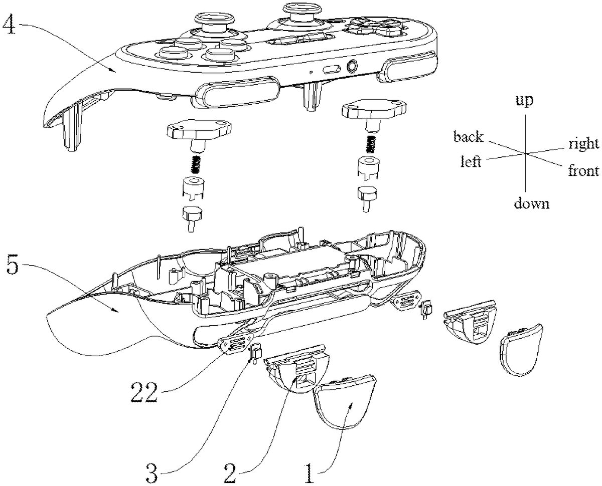
In the description of the invention, it should be understood that, the front side is the side where the trigger button is disposed on the video game controller; the side facing upward when the player is playing the game is the upper side; the left side of the human hand is the left side; the lower side is opposite to the upper side; the left side is opposite to the right side, and the front side is opposite to the back side; orientations or position relationships indicated by terms “up”, “down”, “front”, “back”, “left”, “right”, and the like are orientations or position relationships shown in the accompanying drawings, and these terms are merely used to facilitate description of the present invention and simplify the description, but not to indicate or imply that the mentioned apparatus or element must have a specific orientation and must be constructed and operated in a specific orientation. Therefore, these terms cannot be understood as a limitation to the present invention. In addition, features limited to “first”, “second”, etc. do not constitute a limitation on a specific number. In the invention, unless otherwise stated, the meaning of ‘a plurality of’ is two or more.
In the description of the invention, it should be noted that, unless clear regulation and limitation otherwise, terms “mounting”, “connected” and “connection” should be understood broadly, for example, may be fixed connection and also may be detachable connection or rotatable connection; may be mechanical connection; and may be direct connection, also may be indirection connection through an intermediary, and also may be communication of interiors of two components. The ordinary artisans concerned may understand the specific meaning of terms in this invention according to specific circumstance. The invention is described in detail with reference to drawings and with combination of embodiments.
This embodiment provides a trigger button, as shown inFIGS.1and2, including a mounting base2and a pressing cap1. The mounting base2is connected to a casing of a video game controller, and the pressing cap1is detachably connected to the mounting base2.
The traditional trigger button is an integral structure, which is fixedly connected or rotationally connected to the video game controller. For different players, they have different requirements for the angle of the pressing portion of the trigger button, but the installation and replacement of the traditional trigger button requires the video game controller to be disassembled. In this invention, the trigger button is divided into two parts, including the mounting base2located underneath and the conventional pressing cap1which provides a pressing portion. In this embodiment, the mounting base2is similar to the traditional mounting base, and it may be fixedly or rotationally connected to the casing of the video game controller; and the pressing cap1is detachably connected to the mounting base2. The detachable connection here may include any method such as snap connection, screw connection or magnetic attraction. Thus, the pressing cap1is located above the mounting base2and located on the outside of the video game controller. For different pressing caps, different pressing angles may be set; the pressing cap may be designed in different shapes to meet the pressing habits of different players.
The advantage of this setting is that: through the detachable connection between the pressing cap1and the mounting base2, there is no need to disassemble the video game controller when the player needs to replace the pressing cap, and the pressing cap1is directly removed to replace the different pressing caps.
As shown inFIGS.2and3, the mounting base2and the pressing cap1are respectively provided with a shaft21and a shaft connecting portion11that are matched with each other, and the shaft21is rotatably connected to the shaft connecting portion11.
Through the insertion of the shaft21into the shaft connection portion11, the rotatable connection between the pressing cap1and the mounting base2is realized. It should be noted that, in one embodiment, the shaft21is disposed on the pressing cap1, and the shaft connection portion11is disposed on the mounting base2; in another embodiment, the shaft21is disposed on the mounting base2, and the shaft connection portion11is disposed on the pressing cap1. Certainly, in other embodiments, the shaft connecting portion11may be disposed on the pressing cap1and the mounting base2at the same time, and the shaft is simultaneously inserted into a shaft mounting portion on the pressing cap1and the mounting base2.
The advantage of this design is that: through the rotational connection of the pressing cap1and the mounting base2, the connection of the pressing cap1and the mounting base2is achieved while increasing the flexibility of the connection between the pressing cap1and the mounting base2.
As shown inFIGS.2to6, the trigger button further includes a supporting base3connected to the mounting base2, and the pressing cap1is provided with a supporting pillar12matching with the supporting base3, so that the supporting base3contacts the supporting pillar12when the pressing cap1is pressed.
As mentioned in the foregoing embodiment, different-shaped pressing caps may be provided, and different angles may be adjusted by replacing different pressing caps. The supporting base3is disposed in the mounting base2, and the supporting pillar12is disposed on the pressing cap1, so that the supporting base3contacts the supporting pillar12when the pressing cap1is pressed. For different trigger buttons, the supporting pillar12may be set to different heights, so as to realize the adjustment of different angles of the pressing cap.
As shown inFIGS.4and5, the supporting base3is slidably connected to the mounting base2, and the supporting base3and/or the supporting pillar12at least includes two supporting surfaces with different supporting heights. It should be noted that the supporting surfaces with different supporting heights mean that the supporting heights of different supporting surfaces are different, so that the pressing angle of the trigger button is different.
It should be noted that there are many cases: the supporting surface of the supporting base3may be set to a shape with a different supporting height, similar to a stepped shape; the supporting surface of the supporting pillar12may also be set in a shape with different supporting heights, similar to a stepped shape; and also, the above two may be set to a stepped shape simultaneously. Through the slidable connection of the supporting base3and the mounting base2, switching between different supporting heights is realized. The advantage for simultaneously designing the supporting surface of the supporting base3and the supporting surface of the supporting pillar12with a stepped shape is that: more combinations of supporting height adjustments may be achieved by switching the supporting surfaces of different supporting bases3and supporting pillars12, so that the angle of the trigger button may be switched without disassembling the pressing cap.
As shown inFIGS.2and3, the supporting base3and the mounting base2are respectively provided with a latch31and a chute23, the latch31is plugged and mated with the chute23, and the latch31is slidably connected to the chute23.
It should be noted that, in one embodiment, a latch31is disposed on the supporting base3, and a chute23is disposed on the mounting base2; in another embodiment, a chute23is disposed on the supporting base3, and a latch31is disposed on the mounting base2. As shown inFIGS.2and3, the mounting base2includes a mounting plate22, and the mounting plate22may be fixedly connected to the body of the mounting base or integrally formed therewith. The mounting plate22is provided with the chute23, and a chute31is inserted into the chute23and may slide along the chute23. Through the sliding of the latch31in the chute23, different supporting heights of the supporting base3are adjusted to adjust the angle of the trigger button.
As shown inFIGS.5and6, a toggle switch32is disposed on the supporting base3, the mounting base2is opened with an escape hole25, the toggle switch32is exposed outside the escape hole25, and the toggle switch32is adapted to adjust a position of the latch31in the chute23.
In other words, the supporting base3is disposed inside the mounting base2. In order to facilitate adjustment, the toggle switch32is arranged such that the toggle switch32is exposed from the mounting base2. By pushing the toggle switch32, the position of the supporting base3in the mounting base2may be adjusted, or the position of the supporting base in the chute23may be adjusted. At a corresponding position of the toggle switch32, an escape hole for evading the toggle switch32is opened, wherein the escape hole is a strip-shaped hole, and the longitudinal direction of the strip-shaped hole is parallel to the chute23.
As shown inFIG.1, a video game controller with triggers is provided in this embodiment, including one of the above trigger buttons. The beneficial effects of the video game controller are the same as the trigger buttons described above, and will not be repeated here.
As shown inFIGS.7to12, the video game controller further includes a telescopic assembly6disposed inside the casing of the video game controller. The telescopic assembly6includes at least two supporting portions along a telescopic direction, and a supporting leg24is disposed on the mounting base2, so that the supporting portion contacts the supporting leg24when the pressing cap1is pressed to a limit position. The limit position here refers to the position at the maximum displacement that may be moved by pressing the pressing cap1.
As shown inFIG.1, the trigger button is disposed at a front end of the video game controller, the telescopic direction of the telescopic assembly6is arranged up and down, and the telescopic assembly6includes at least two supporting portions along the telescopic direction. Through the provision of the supporting leg24on the mounting base2, limitation may be exerted on the supporting leg24in different supporting portions, thereby adjusting the pressing stroke of the pressing cap. Through different pressing strokes, the requirements of different players may be met. In other words, through the provision of different supporting portions, the adjustment for different angles of the pressing cap may be realized at the limit position.
As shown inFIGS.10to12, the telescopic assembly6includes a guide member61, a pressing push rod62, a rotation member63, a compression spring64and a fixed base65. The guide member61is fixedly connected to the casing of the video game controller, and the compression spring64is located between the rotation member63and the fixed base65. The guide member61is annular, and an inner wall of the guide member61is provided with a guide groove612. The guide member61is provided circumferentially with at least two abutting portions611, and the rotation member63is provided with abutting members632matching the abutting portions611. The compression spring pushes the abutting portions611into contact with the abutting members632, and the pressing push rod62is slidably connected with the guide member61. When the pressing push rod62is pressed, the pressing push rod62pushes the rotation member63to move linearly. When the pressing push rod62moves to a set position, the rotation member63rotates under the action of the compression spring.
It should be noted that, in this embodiment, as shown inFIG.1, the video game controller includes an upper casing4and a lower casing5. The telescopic assembly6adopts the working principle of a telescopic ballpoint pen. When the ballpoint pen is pressed, the pen head extends; and when the ballpoint pen is pressed again, the pen head retracts. As shown inFIGS.10to12, in this embodiment, the guide member61is mounted on the lower casing5, and an inner wall of the guide member is provided with a guide groove612; the pressing push rod62also has a cylindrical surface matching the inner wall of the guide member, and the circumferential surface of the pressing push rod62is provided with a guide protrusion621. The guide protrusion621is slidably connected to the guide groove612, and the cross-sectional projection of the abutting portion611is a right triangle, or the abutting portion611has a right-angled tooth shape, and the contact surface between the abutting portion611and the abutting member632is an arc-shaped surface or an inclined surface. The guide groove612is located between adjacent abutting portions611. When the pressing push rod62pushes the rotation member63to make a linear movement, and when the rotation member63reaches the uppermost end of the abutting portion611(i.e., the set position), the rotation member63moves along the contact surface of the abutting portion to the adjacent abutting portion611under the action of the compression spring64, thereby achieving the rotation of the rotation member63. The height of the position where the abutting portion611contacts the abutting member632is different, and the height of the rotation member63is adjusted by different heights. The height of the position where the abutting portion611contacts the abutting member632has at least two different heights. The fixed base65is mounted on the upper casing4, a lower end of the fixed base65is provided with a spring receiving groove652(in the figure, the spring receiving groove652is shown as penetrating through the fixed base65, but in reality, it may be partially penetrated through the fixed base65), and the compressing spring is received in the spring receiving groove652, so that a limitation is exerted on the compressing spring. It should be noted that an initial length of the compression spring is greater than a depth of the spring receiving groove. The pressing portion of the pressing push rod62is located on a lower side of the lower casing5.
As shown inFIGS.10to12, a cylindrical groove631is disposed on an upper end of the rotation member63, the second cylindrical surface651is disposed on the fixed base65, and the second cylindrical surface651is inserted into the cylindrical groove631, so that the compression spring is located between the spring receiving groove652and the cylindrical groove631.FIG.7is a view showing a state of un-pressing the trigger button,FIG.8is a view showing a state where the trigger button is pressed to a limit position, and theFIG.9is a view showing another state where the trigger button is pressed to a limit position. The supporting portion includes a first cylindrical surface633and a second cylindrical surface651; the first cylindrical surface633is disposed on the rotation member63, and the second cylindrical surface651is disposed on the fixed base65; axial directions of the first cylindrical surface633and the second cylindrical surface651are the same as the telescopic direction of the telescopic assembly6.
As shown inFIG.7, a rotation shaft26is disposed on the mounting base2, and the trigger button is connected to the upper casing through the rotation shaft. When the trigger button is pressed, the trigger button rotates around the rotation shaft26; and when the trigger button is released, the trigger button is restored to the initial position automatically. As shown inFIG.8, when the trigger button is pressed, the supporting portion is the first cylindrical surface633; and when the trigger button is at the limit position, the supporting leg24contacts the first cylindrical surface633, which is equivalent to the first cylindrical surface633limiting a first button stroke of the trigger button. As shown inFIG.9, the pressing push rod is pressed to switch the button strokes of the trigger button. At this time, when the trigger button is pressed, the supporting portion is the second cylindrical surface651; and when the trigger button is at the limit position, the supporting leg24contacts the second cylindrical surface651, which is equivalent to the second cylindrical surface651limiting a second button stroke of the trigger button.
Optionally, the diameters of the first cylindrical surface633and the second cylindrical surface651are different. Through setting different diameters, different positions of the supporting leg24are defined.
The advantage of the setting is that: the players may choose the appropriate button-stroke and angle of the pressing cap according to their own needs, so that the same video game controller may meet the requirements of different players without repeatedly changing the trigger button for the same product. The working principle similar to the ballpoint pen is used to adjust the button-stroke of the trigger button, and the first cylindrical surface633and the second cylindrical surface651are used as the supporting portions, which is convenient for adjustment.
It should be noted that the supporting portion may also have other shapes, such as polygonal surfaces or arc-shaped surfaces, etc., and is not necessarily limited to cylindrical surfaces. In this embodiment, the pressing signal is triggered by the contact between the supporting leg24and the supporting portion.
The above are only preferred embodiments of this invention and are not intended to limit this invention. Any modification, equivalent replacement, improvement, etc. made by any person skilled in the art within the spirit and principle of this invention should also be included in the scope of this invention.
Claims
- A trigger button, comprising: a mounting base and a pressing cap, the mounting base being connected to a casing of a video game controller, the pressing cap being detachably connected to the mounting base;wherein the trigger button further comprises a supporting base connected to the mounting base, a supporting pillar matching with the supporting base is disposed on the pressing cap, and the supporting base contacts the supporting pillar when the pressing cap is pressed;wherein the supporting base is slidably connected to the mounting base, and the supporting base and/or the supporting pillar at least comprises two supporting surfaces with different supporting heights;wherein the supporting base and the mounting base are respectively provided with a latch and a chute, the latch is plugged and mated with the chute, and the latch is slidably connected to the chute.
- The trigger button according to claim 1, wherein the mounting base and the pressing cap are respectively provided with a shaft and a shaft connecting portion that are matched with each other, and the shaft is rotatably connected to the shaft connecting portion.
- The trigger button according to claim 1, wherein a toggle switch is disposed on the supporting base, the mounting base is opened with an escape hole, the toggle switch is exposed outside the escape hole, and the toggle switch is adapted to adjust a position of the latch in the chute.
- A video game controller with triggers, comprising: a trigger button, comprising: a mounting base and a pressing cap, the mounting base being connected to a casing of the video game controller, the pressing cap being detachably connected to the mounting base;a telescopic assembly disposed within the casing of the video game controller, the telescopic assembly comprises at least two supporting portions along a telescopic direction, the mounting base is provided with a supporting leg, and the supporting portions are adapted to support the supporting leg;wherein the telescopic assembly comprises a guide member, a pressing push rod, a rotation member, a compression spring and a fixed base;the guide member is fixedly connected to the casing of the video game controller, and the compression spring is located between the rotation member and the fixed base;the guide member is annular, and a guide groove is disposed on an inner wall of the guide member;at least two abutting portions are circumferentially disposed on the guide member, and abutting members matching the abutting portions are disposed on the rotation member;the compression spring pushes the abutting portions into contact with the abutting members, and the pressing push rod is slidably connected with the guide member;when the pressing push rod is pressed, the pressing push rod pushes the rotation member to move linearly;when the pressing push rod moves to a set position, the rotation member rotates under the action of the compression spring.
- The video game controller with triggers according to claim 4, wherein the supporting portion comprises a first cylindrical surface and a second cylindrical surface;the first cylindrical surface is disposed on the rotation member, and the second cylindrical surface is disposed on the fixed base;axial directions of the first cylindrical surface and the second cylindrical surface are the same as the telescopic direction of the telescopic assembly.
Disclaimer: Data collected from the USPTO and may be malformed, incomplete, and/or otherwise inaccurate.