U.S. Pat. No. 11,779,835
VIDEO GAME CONTROLLER
AssigneeHUBEI ZUANMA INTELLIGENT CONTROL TECHNOLOGY CO., LTD
Issue DateOctober 12, 2022
Illustrative Figure
Abstract
A video game controller includes a first controller outer housing and a second controller outer housing. The first controller outer housing and the second controller outer housing are detachably connected. A first controller inner housing, a second controller inner housing, a battery, and a wireless charging board are disposed in the first controller outer housing and the second controller outer housing. A control board is disposed in the second controller outer housing, and the control board is electrically connected to the wireless charging board. A lighting assembly is disposed on the control board, and the lighting assembly is configured to emit light for the video game controller. The first controller outer housing and the second controller outer housing are made of a transparent material, and the first controller inner housing and the second controller inner housing are in semi-transparent structures.
Description
DETAILED DESCRIPTION In order to make the objectives, technical solutions, and advantages of the present disclosure clearer, the following further describes the present disclosure in detail with reference to the accompanying drawings and embodiments. It should be understood that the specific embodiments described herein are merely used to explain the present disclosure and are not intended to limit the present disclosure. In the description of the present disclosure, it should be noted that, unless specified or limited otherwise, the terms “disposed”, “connected with”, and “connected to” should be understood in a broad sense, for example, may be a fixed connection, a detachable connection, or an integral connection; may be a mechanical connection, or may be an electrical connection, may be a direct connection, may also be indirectly connected by means of an intermediate medium, or may be a communication between two elements, may be a wireless connection, or may be a wired connection. For a person of ordinary skill in the art, the specific meanings of the above terms in the present disclosure may be understood in detail. In the description of the present disclosure, it should be noted that the orientations or positional relationships indicated by the terms “center”, “upper”, “lower”, “left”, “right”, “vertical”, “horizontal”, “inner”, “outer”, etc. are based on the orientation or positional relationship shown in the drawings, and are merely intended to facilitate describing the present disclosure and simplifying the description, rather than indicating or implying that the indicated apparatus or element must have a specific orientation, be constructed and operated in a specific orientation, and therefore cannot be understood as a limitation to the present disclosure. In addition, the terms “first”, “second”, and “third” are used for descriptive purposes only and are not to be construed as indicating or implying relative importance. In addition, the ...
DETAILED DESCRIPTION
In order to make the objectives, technical solutions, and advantages of the present disclosure clearer, the following further describes the present disclosure in detail with reference to the accompanying drawings and embodiments. It should be understood that the specific embodiments described herein are merely used to explain the present disclosure and are not intended to limit the present disclosure.
In the description of the present disclosure, it should be noted that, unless specified or limited otherwise, the terms “disposed”, “connected with”, and “connected to” should be understood in a broad sense, for example, may be a fixed connection, a detachable connection, or an integral connection; may be a mechanical connection, or may be an electrical connection, may be a direct connection, may also be indirectly connected by means of an intermediate medium, or may be a communication between two elements, may be a wireless connection, or may be a wired connection. For a person of ordinary skill in the art, the specific meanings of the above terms in the present disclosure may be understood in detail.
In the description of the present disclosure, it should be noted that the orientations or positional relationships indicated by the terms “center”, “upper”, “lower”, “left”, “right”, “vertical”, “horizontal”, “inner”, “outer”, etc. are based on the orientation or positional relationship shown in the drawings, and are merely intended to facilitate describing the present disclosure and simplifying the description, rather than indicating or implying that the indicated apparatus or element must have a specific orientation, be constructed and operated in a specific orientation, and therefore cannot be understood as a limitation to the present disclosure. In addition, the terms “first”, “second”, and “third” are used for descriptive purposes only and are not to be construed as indicating or implying relative importance.
In addition, the technical features involved in the different embodiments of the present disclosure described below can be combined with each other as long as they do not conflict with each other.
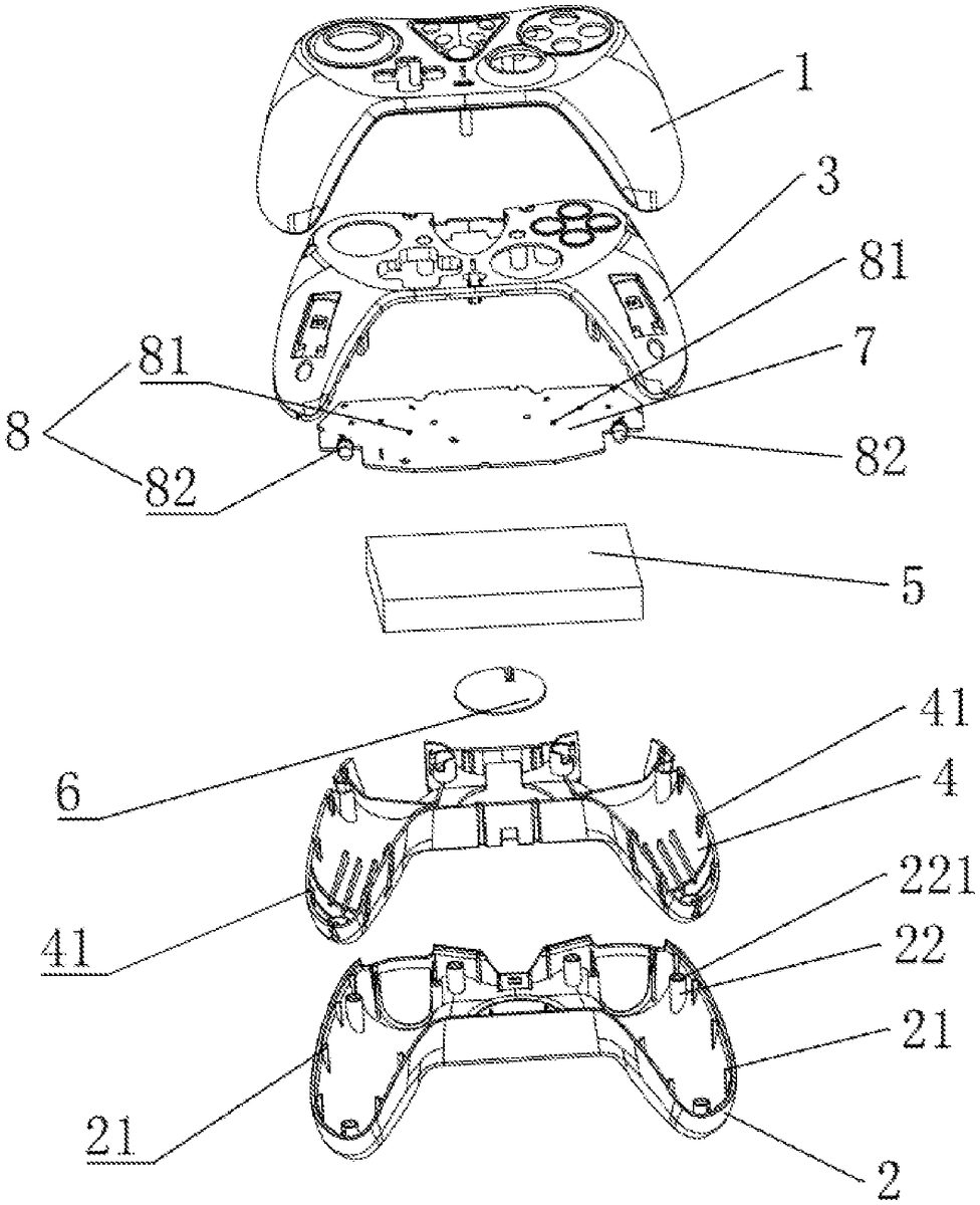
The present disclosure provides a video game controller, as shown inFIGS.1-4, including a first controller outer housing1and a second controller outer housing2. The first controller outer housing1and the second controller outer housing2are detachably connected. A first controller inner housing3, a second controller inner housing4, a battery5, and a wireless charging board6are disposed in the first controller outer housing1and the second controller outer housing2. The wireless charging board6is configured to wirelessly charge the battery5. A control board7is disposed in the second controller outer housing4, and the control board7is electrically connected to the wireless charging board6. A lighting assembly8is disposed on the control board7, and the lighting assembly8is configured to emit light for the video game controller. The first controller outer housing1and the second controller outer housing2are made of a transparent material, and the first controller inner housing3and the second controller inner housing4are in semi-transparent structures.
It should be noted that the wireless charging board6is configured to wirelessly charge, which is convenient for wirelessly charging the video game controller. The lighting assembly8is configured to emit light, which is convenient for lighting display of the video game controller. Thereby, the present disclosure provides the video game controller having a wireless charging function and a light-emitting function, which increases functionality of the video game controller and further improves experience feeling of users.
As shown inFIGS.1-2, the lighting assembly8includes first lighting lamps81and second lighting lamps82, and the first lighting lamps81and the second lighting lamps82are respectively and electrically connected to the control board7.
As shown inFIGS.1-2, a lighting assembly8of a video game controller of the present disclosure includes eight first lighting lamps81, four of the eight first lighting lamps81are distributed at a first end of the control board7, and another four of the eight first light lamps81are distributed at a second end of the control board7. In the embodiment, the eight first lighting lamps81are SMD LEDs.
As shown inFIGS.1-2, a lighting assembly8of a video game controller of the present disclosure includes two second lighting lamps82, and the two second lighting lamps82are respectively distributed at two opposite ends of the control board7. In the embodiment, the two second lighting lamps82are LED bulbs.
As shown inFIGS.1-2, first positioning columns11are disposed in the first controller outer housing11, first positioning grooves31are defined on the first controller inner housing3, where the first positioning grooves31are matched with the first positioning columns11for inserting. Second positioning blocks21are disposed in the second controller outer housing2, second positioning grooves41are defined on the second controller inner housing4, where the second positioning grooves41are matched with the second positioning blocks21for positioning.
It should be noted that the video game controller of the present disclosure provides multiple first positioning columns11, multiple first positioning grooves31, multiple second positioning blocks21, and multiple second positioning grooves41. The first positioning columns11are matched with the first positioning grooves31for inserting, so that the first controller inner housing3is tightly disposed in the first controller outer housing1. The second positioning blocks21are matched with the second positioning groove41for positioning, so that the second controller inner housing4is tightly disposed in the second controller outer housing2. Thereby, the inner housings and the outer housings of the video game controller of the present disclosure are tightly assembled.
As shown inFIGS.1-2, second positioning columns22are disposed in the second controller outer housing2, and the second positioning columns22are matched with the first positioning columns11for inserting. Positioning lug bosses221are disposed in the second positioning columns22, and the positioning lug bosses221abut against the first positioning columns11. It should be noted that the first positioning columns11are matched with the second positioning columns22for inserting, which is convenient for assemble the video game controller, and the positioning lug bosses221are configured to limit, when the first positioning columns11abut against the positioning pug bosses221, the first positioning columns11are inserted in place.
As shown inFIGS.1-2, first positioning holes111, having inner screw threads, are defined in the first positioning columns11. Second positioning holes222are defined in the second positioning columns22, and the second positioning holes222are matched with the first positioning holes111. The first controller outer housing1and the second controller outer housing2are connected through screws. It should be noted that the video game controller of the present disclosure provides the multiple first positioning columns11and the multiple second positioning columns22. The screws penetrate through the second positioning holes222to be in threaded connection with the first positioning holes111, which is convenient for disassembling the video game controller.
As shown inFIGS.1-2, several control buttons9are connected to the control board7, and the several control buttons9are configured to control game programs. In the embodiment, the control buttons9include a direction button, a function button, a selection button, and a menu button.
As shown inFIGS.1-2, concave grooves23are defined on the second controller outer housing2. It should be noted that the concave grooves23are configured to place fingers of the users inside, which is convenient for holding and further improves experience feeling of users.
Working principle of the present disclosure is as follows.
The wireless charging board6of the present disclosure is configured to wirelessly charge, which is convenient for wirelessly charging the video game controller. The lighting assembly8of the present disclosure is configured to emit light, which is convenient for lighting display of the video game controller. Thereby, the present disclosure provides the video game controller having a wireless charging function and a light-emitting function, which increases functionality of the video game controller and further improves the experience feeling of the users.
Apparently, the above embodiments are merely examples for clearly illustrating the embodiments, and are not intended to limit the embodiments. For the person of ordinary skill in the art, other different forms of changes or variations can be made on the basis of the above description. It is not necessary for all implementations to be exhaustive here. The obvious changes or variations derived therefrom are still within the scope of protection of the present disclosure.
Claims
- A video game controller, comprising: a first controller outer housing;and a second controller outer housing;wherein the first controller outer housing and the second controller outer housing are detachably connected;a first controller inner housing, a second controller inner housing, a battery, and a wireless charging board are disposed in the first controller outer housing and the second controller outer housing;the wireless charging board is configured to wirelessly charge the battery;a control board is disposed in the second controller outer housing, and the control board is electrically connected to the wireless charging board;a lighting assembly is disposed on the control board, and the lighting assembly is configured to emit light for the video game controller;the first controller outer housing and the second controller outer housing are made of a transparent material, and the first controller inner housing and the second controller inner housing are in semi-transparent structures;wherein first positioning columns are disposed in the first controller outer housing, first positioning grooves are defined on the first controller inner housing, where the first positioning grooves are matched with the first positioning columns for inserting;second positioning blocks are disposed in a bottom edge of the second controller outer housing, second positioning grooves are defined on a bottom edge of the second controller inner housing, where the second positioning grooves are matched with the second positioning blocks for positioning;wherein concave grooves are defined on the second controller outer housing to place fingers of the users inside for conveniently holding the second controller outer housing.
- The video game controller according to claim 1, wherein the lighting assembly comprises first lighting lamps and second lighting lamps, and the first lighting lamps and the second lighting lamps are respectively and electrically connected to the control board.
- The video game controller according to claim 2, wherein the lighting assembly comprises eight first lighting lamps, four of the eight first lighting lamps are distributed at a first end of the control board, and another four of the eight first light lamps are distributed at a second end of the control board.
- The video game controller according to claim 2, wherein the lighting assembly comprises two second lighting lamps, and the two second lighting lamps are respectively distributed at two opposite ends of the control board.
- The video game controller according to claim 1, wherein the first positioning grooves are defined on a side wall of the first controller inner housing, and the first positioning grooves are matched with the second positioning blocks for positioning.
- The video game controller according to claim 1, wherein second positioning columns are disposed in the second controller outer housing, and the second positioning columns are matched with the first positioning columns for inserting;positioning lug bosses are disposed in the second positioning columns, and the positioning lug bosses abut against the first positioning columns.
- The video game controller according to claim 6, wherein first positioning holes, having inner screw threads, are defined in the first positioning columns;second positioning holes are defined in the second positioning columns, and the second positioning holes are matched with the first positioning holes;the first controller outer housing and the second controller outer housing are connected through screws.
- The video game controller according to claim 1, wherein several control buttons are connected to the control board, and the several control buttons are configured to control game programs.
Disclaimer: Data collected from the USPTO and may be malformed, incomplete, and/or otherwise inaccurate.