U.S. Pat. No. 11,772,001
GAME PROCESSING PROGRAM, GAME PROCESSING METHOD, AND GAME PROCESSING DEVICE
AssigneeGREE Holdings Inc
Issue DateApril 6, 2021
Illustrative Figure
Abstract
A game processing device changes a movement direction of a moving object from a first direction, which is a movement direction of the moving object, to a second direction based on an operation direction of the controller if an operation of the controller in a direction that is different from the first direction is detected.
Description
DETAILED DESCRIPTION OF THE PREFERRED EMBODIMENTS First Embodiment A first embodiment of a game processing program, a game processing method, and a game processing device will now be described. In the present embodiment, the game processing device executes the game processing program in a state in which each player wears a head-mounted display (HMD) on the head, thereby presenting the player with a game in which a controller is used for input operations. In the present embodiment, a case in which two players simultaneously play the game will be described. [Overview of System] The systems of an HMD10, controllers20, and a game processing device30will now be described with reference toFIG.1. First, the HMD10that is connected to the game processing device30will be described. The HMD10includes an HMD controller11, a sensor12, and an input/output interface (I/F)13. The HMD controller11outputs various information to the game processing device30via the input/output I/F13and receives various information that is input from the game processing device30. The sensor12is a sensor that detects motion of the head of a player including the position and orientation of the head of the player. The sensor12includes, for example, at least one of a gyro sensor, an acceleration sensor, and a geomagnetic sensor. Further, the HMD10includes a display14for displaying an image and a speaker15for outputting audio. For example, the display14displays an image for the left eye and an image for the right eye with a parallax. This allows the player to look at a three-dimensional image with depth perception. The HMD controller11displays, on the display14, an image corresponding to an image signal received from the game processing device30via the input/output I/F13. The speaker15is, for example, a headphone and outputs a sound effect, audio or the like that explains the progress of the game. The sensor12and the speaker15may be arranged separately from the HMD10. ...
DETAILED DESCRIPTION OF THE PREFERRED EMBODIMENTS
First Embodiment
A first embodiment of a game processing program, a game processing method, and a game processing device will now be described. In the present embodiment, the game processing device executes the game processing program in a state in which each player wears a head-mounted display (HMD) on the head, thereby presenting the player with a game in which a controller is used for input operations. In the present embodiment, a case in which two players simultaneously play the game will be described.
[Overview of System]
The systems of an HMD10, controllers20, and a game processing device30will now be described with reference toFIG.1. First, the HMD10that is connected to the game processing device30will be described. The HMD10includes an HMD controller11, a sensor12, and an input/output interface (I/F)13. The HMD controller11outputs various information to the game processing device30via the input/output I/F13and receives various information that is input from the game processing device30. The sensor12is a sensor that detects motion of the head of a player including the position and orientation of the head of the player. The sensor12includes, for example, at least one of a gyro sensor, an acceleration sensor, and a geomagnetic sensor.
Further, the HMD10includes a display14for displaying an image and a speaker15for outputting audio. For example, the display14displays an image for the left eye and an image for the right eye with a parallax. This allows the player to look at a three-dimensional image with depth perception. The HMD controller11displays, on the display14, an image corresponding to an image signal received from the game processing device30via the input/output I/F13. The speaker15is, for example, a headphone and outputs a sound effect, audio or the like that explains the progress of the game. The sensor12and the speaker15may be arranged separately from the HMD10.
Each controller20detects motion of the controller20including the position and orientation of the controller20. The controller20includes, for example, at least one of a gyro sensor, an acceleration sensor, and a geomagnetic sensor. Further, the controller20includes a determination button. The controller20outputs, to the game processing device30, various information including the detection result of the motion of the controller20and whether or not the determination button has been operated (for example, tapping operation). The controller20may be a controller including an operation portion other than the determination button or may be a controller that accepts an input operation performed on the touch panel display.
[Game Processing Device30]
The game processing device30will now be described. The game processing device30includes a control unit31, a memory unit32, and an input/output unit33. The control unit31includes hardware elements such as a CPU, a RAM, and a ROM. Further, the control unit31includes an operation state determination unit34, a game management unit35, and a display control unit36. In the present embodiment, the control unit31functions as the operation state determination unit34, the game management unit35, and the display control unit36by causing the hardware elements to execute the game processing program.
The memory unit32stores game field information37, avatar information38, moving object information39, item information40, operation state information41, and an object catching history42.
The game field information37is data used to draw the background of a game field shared by two players. The game field information37includes information related to the initial position for an avatar arranged in the game field by each player as a game element, information related to the type of moving object arranged in the game field, and the like.
The avatar information38is data used to draw the avatars arranged in the game field and respectively associated with the players when the game is executed.
The moving object information39is information related to a moving object displayed in the game field. The moving object information39includes movement range information used to set a movement range of the moving object in the game field, an attribute of an moving object (for example, parameter of moving object related to difficulty level indicating catching difficulty), and the like. The catching of a moving object means the provision of the moving object to a player and is achieved by recording identification information of the player in association with identification information of the moving object.
The item information40is information related to an item used to catch a moving object by operating the controllers20. The item information40includes an attribute of the item (for example, parameter of item that contributes to catching of moving object).
The operation state information41is information indicating the operation state of each controller20. The operation state information41includes information indicating the movement state including an operation speed that includes at least one of the speed, acceleration, and angular velocity of the controller20, information indicating the tilted direction of the controller20, information indicating whether or not the determination button of the controller20is operated, and the like. In the present embodiment, information indicating the operation state of the controller20is recorded for each controller20operated by the corresponding player.
The object catching history42includes information indicating the type of moving object that has been successfully caught by operating the controller20. The object catching history42is managed as individual history data for each player.
An operation signal is input to the operation state determination unit34of the control unit31from the controller20operated by each player via the input/output unit33. Further, the operation state determination unit34uses the input operation signal to determine the operation state of the controller20and record the determined operation state in the memory unit32.
The game management unit35manages the progress made in the game by a player. More specifically, if the player first selects a game field, an avatar is arranged in the selected game field. Further, the game management unit35uses movement range information corresponding to the type of moving object included in the game field information37to determine the movement range of the moving object in the game field. In addition, the game management unit35performs a catch operation on the moving object moving in the movement range in the game field based on operation states of the controllers20determined by the operation state determination unit34. If the catch operation on the moving object succeeds, the game management unit35adds the type and the like of the caught moving object to the object catching history42. If the catch operation on the moving object fails, the game management unit35ends the game. Additionally, the game management unit35extracts, from an audio information memory (not shown), audio information such as a sound effect and an audio explaining the progress of the game and transmits audio information to the speaker15via the input/output unit33.
The display control unit36determines an eyesight range in a virtual space centered about an attention position of each player and extracts the game field information37corresponding to the eyesight range. The display control unit36transmits the extracted game field information to the HMD10as an image signal. Further, the display control unit36displays the background of the game field selected by the player, an image of a moving object moving in the selected game field, and the like. In addition, the display control unit36displays, to each player, an avatar corresponding to the player in the game field.
[Operation Control]
The determination function of an operation state of each controller20by the game processing device30will now be described with reference toFIG.2. The operation state determination unit34determines the position and orientation of the head of a player101corresponding to a detection signal of the sensor12input from the HMD10. More specifically, the operation state determination unit34calculates the position and orientation of the head as positions in three axes, namely, X-axis in a horizontal direction, Y-axis in a vertical direction, and Z-axis in a depth-wise direction, and angles about the three axes. A rotation angle about the X-axis is represented by a pitch θ p, a rotation angle about the Y-axis is represented by a yaw θ y, and a rotation angle about the Z-axis is represented by a roll θ r. The operation state determination unit34determines the eyesight position of the player in a virtual space100based on the determined position and orientation of the head. The attention position in the virtual space may be determined by determining only the orientation of the head of the player. The “attention position” is a point of the coordinates or a region in the virtual space. Further, the method for determining the attention position is not limited to the method described herein.
Further, the operation state determination unit34determines the position and orientation of each controller20based on various information such as the input operation signal of the controller20. More specifically, the operation state determination unit34calculates the position and orientation of the controller20as the positions in the three axes and the angles about the three axes in the same manner as the head of each player101. The operation state determination unit34determines the operation state of the controller20as viewed from the viewpoint of the player101by comparing the determined position and orientation of the controller20with the position and orientation of the head of the player101.
The display control unit36displays, at a position in the virtual space100corresponding to the controller20, an image of an item103used to operate moving objects in a game field102. In the present embodiment, an image of fishing rod used to catch moving objects is displayed near the hand of the player101.
The virtual space is shared by two players101. Thus, if operation performed by one of the players101is included in the eyesight range of the other one of the players101, the display14of the latter player101displays the operation performed by the former player101. Further, if operation performed by one of the players101causes a change in a moving object moving in the game field, the change is reflected on the display of the other one of the players101.
[Game Process]
Each process for presenting a game to a player will now be described with reference toFIGS.3to14. In the present embodiment, each process will be described as an example game for catching a moving object.
When the game starts, the control unit31of the game processing device30determines the position and orientation of the head corresponding to the detection signal input from the sensor12of the HMD10. The control unit31determines an attention position of a player based on the position and orientation of the head. The control unit31extracts, from the memory unit32, the game field information37of an eyesight range centered about the attention position. The control unit31also transmits, to the HMD controller11, an image signal of a game field and a moving object that are included in the extracted game field information37. The control unit31determines the position and orientation of the controller20corresponding to an operation signal input from the controller20. The control unit31reads the item information40from the memory unit32and transmits, to the HMD controller11, an image signal of an item included in the read item information40. The HMD controller11outputs an image corresponding to the received image signal to the display14. More specifically, the HMD controller11outputs, to the display14, an image that displays the game field and the moving object at their respective predetermined positions in the virtual space. The HMD controller11outputs, to the display14, an image in which an item is displayed at the position corresponding to the controller20. In this manner, the game processing device30progresses the game while displaying, on the display14, an image of the virtual space that corresponds to the position and orientation of the head of the player as well as the position and orientation of the controller20.
[Game Progress Process]
The game progress process will now be described with reference toFIG.3.
First, the control unit31of the game processing device30executes an environment setting of the game (step S10). When the game starts, the control unit31reads the game field information37from the memory unit32. The process will be described later in detail with reference toFIG.4.
Next, if the environment setting of the game is completed, the control unit31proceeds to a standby mode (step S20). If a predetermined starting event is detected in the standby mode, the control unit31proceeds to a battle mode (step S30). The process will be described in detail later with reference toFIGS.8and9.
Then, the control unit31determines whether or not the player has performed a game ending operation after the battle mode ends (step40).
If the game ending operation has not been performed (“NO” in step S40), the control unit31returns to step S20. If the game ending operation has been performed (“YES” in step S40), the control unit31causes the game to be ended.
[Environment Setting of Game]
The environment setting of the game will now be described with reference toFIG.4. First, based on an operation signal input from the controller20, the control unit31of the game processing device30selects a game field selected by a player from a plurality of game fields that are prepared in advance (step S11).
Next, the control unit31sets a moving object for the selected game field (step S12). More specifically, the game management unit35of the control unit31determines the type of moving object corresponding to the selected game field based on the game field information37. Further, the game management unit35extracts, from the moving object information39, movement range information used to set a movement range of the determined moving object. The control unit31determines the movement range of the moving object in the game field based on the extracted movement range information.
Subsequently, the control unit31receives player information (step S13). More specifically, the control unit31determines the number of players and a player ID for each player based on an operation signal input from the corresponding controller20.
Then, the control unit31sets an avatar (step14). More specifically, the game management unit35of the control unit31reads the avatar information38from the memory unit32and sets an avatar for each player. Further, the game management unit35extracts, from the game field information37, information related to an initial position for the avatar corresponding to the selected game field. In this case, a plurality of positions are set in advance as the initial position for the avatar in the game field, and each position is determined based on movement ranges of moving objects. More specifically, the relative position of the avatar and a moving object is determined so that the distance from the initial position for the avatar to the movement range of the moving object is smaller than a predetermined distance. Thus, the movement range of at least one of the moving objects moving in the game field102is located proximate to the initial position for every one of the avatars. The control unit31randomly selects the initial position for an avatar for each player from the initial positions for the avatar corresponding to the game field. Alternatively, the control unit31selects the position designated by a player from the initial positions for the avatar.
The virtual space that is set through the environment setting of the game will now be described with reference toFIG.5. The virtual space inFIG.5is schematically shown irrelevant to the eyesight range of a player.
As shown inFIG.5, a movable range105of moving objects104are set in the game field102selected by two players. In the present embodiment, a fishing spot corresponds to the game field102, fish correspond to the moving objects104, and a pond corresponds to the movable range105of the moving objects104. Movement target positions106of the moving objects104are set for the movable range105of the moving objects104based on the moving object information39. The number, arrangement, and movement probability of the movement target positions106(i.e., probability of a moving object104moving to each movement target position106) differ depending on the type of the moving object104. The range surrounded by the movement target positions106corresponds to a movement range107of each moving object104. When a fish, which is the moving object104, exists in a pond (or river, sea, and the like), which is the movable range105, the fish is displayed by a fish outline.
Further, the game field102displays avatars108that are respectively set for the players. The movement range107of at least one of the moving objects104moving in the game field102is arranged to be included in the vicinity of the initial position for each avatar108. In the present embodiment, two moving objects104wander in the game field102, and the movement range107of one of the two moving objects104is arranged in the proximity of each of the avatars108of two players. This allows the two players to immediately start catching operation of moving objects104and smoothly progress the game without changing the positions of their avatars108from when the game starts.
[Standby Mode]
The standby mode will now be described with reference toFIG.6.
First, the control unit31of the game processing device30detects operation performed in a first direction (step S21). More specifically, the operation state determination unit34of the control unit31detects a swing-down operation of the controller20, as the operation performed in the first direction, from an operation signal input from the controller20.
Next, the control unit31executes a first operation rendering based on the operation state of the operation of the controller20in the first direction (step S22). More specifically, the display control unit36of the control unit31arranges, in the game field, an item related to a catch operation performed on a moving object as the first operation rendering. The operation state of the operation performed in the first direction includes the operation speed and orientation of the operation of the controller20in the first direction. If an item is arranged in the game field, the control unit31controls the catching operation of the moving object to be ready to start.
Then, the control unit31determines whether or not a preparation condition of the operation of the controller20in a second direction has been satisfied (step S23). In the present embodiment, a swing-up operation of the controller20is used as the operation performed in the second direction.
More specifically, if the relative positions of a moving object and an item in the game field become closer and less than or equal to a predetermined distance, the operation state determination unit34of the control unit31associates the moving object with the item and determines that the preparation condition of the operation performed in the second direction has been satisfied.
If the control unit31determines that the preparation condition of the operation performed in the second direction has been satisfied (“YES” in step S23), the control unit31determines whether or not the controller20has been operated in the second direction within a reference time (step S24). More specifically, the operation state determination unit34of the control unit31waits for the operation performed in the second direction while measuring the time from when the preparation condition of the operation performed in the second direction is satisfied.
If the control unit31determines that the controller20has been operated in the second direction within the reference time (“YES” in step S24), the control unit31executes a second operation rendering (step S25). More specifically, the display control unit36of the control unit31outputs, to the HMD10, an operation rendering that displays a message indicating shifting to the battle mode in the vicinity of a moving object.
If the control unit31determines that the preparation condition of the operation of the controller20performed in the second direction has not been satisfied (“NO” in step S23), the control unit31determines whether or not a cancellation operation has been performed (step S26). More specifically, the operation state determination unit34of the control unit31waits for, as the cancellation operation, the swing-up operation of the controller20based on an operation signal input from the controller20that is operation performed in a direction opposite to the first direction.
If the cancellation operation is detected (“YES” in step S26), the control unit31cancels the first operation rendering (step S27) and returns to step S21.
If the cancellation operation is not detected (“NO” in step S26), the control unit31returns to step S23while continuing the first operation rendering.
Further, the control unit31determines that the controller20has not been operated in the second direction within the reference time (“NO” in step S24), cancels the first operation rendering (step S27) and returns to step S21in the same manner.
The image displayed on the display14of the HMD10during execution of the standby mode will now be described with reference toFIGS.7A to7D.
As shown inFIG.7A, the control unit31of the game processing device30displays, on the display14, an image of the virtual space in which the attention position of the player is located at the center of the eyesight range. In this case, the display control unit36of the control unit31displays, as the image of the virtual space, the game field102, the moving object104(fish) moving in the game field102, and the item103(fishing rod) associated with operation of the controller20.
As shown inFIG.7B, if the operation of the controller20in the first direction is detected, the control unit31executes the first operation rendering in which the item109(lure or bait) is arranged in the movable range105of the moving object104, which is set in the game field102as a set region. In the present embodiment, as the first operation rendering, a video is output in which a lure is thrown into a water surface of the pond from the head of the fishing rod.
In this case, the control unit31determines the position of the item109in the game field102based on a movement state (operation speed, orientation) of the controller20in the operation performed in the first direction. More specifically, the game management unit35of the control unit31arranges the item109at a farther position as viewed from the viewpoint of the player for a higher speed or higher acceleration of the controller20in the operation performed in the first direction (swing-down operation). In this case, the item109is arranged at a point on an extension line lying in the operation direction (swing-down direction), which is the first direction as viewed from the viewpoint of the player.
Further, as shown inFIG.7C, if the relative positions of the moving object104and the item109(for example, lure) in the game field102are proximate, the control unit31determines whether or not the moving object104is associated with the item109based on the affinity of the moving object104and the item109. More specifically, the game management unit35of the control unit31determines battle start (association of moving object104with item109) based on the affinity of a fish and a lure or the like. The affinity of the bait set to the lure with the type of fish affects whether or not “hooking” in which the fish bites the lure has succeeded.
Further, if the moving object104and the item109are associated with each other, the control unit31issues a notification to the player. In this case, one example of a notification is to vibrate the controller20with a vibration function incorporated in the controller20. However, the notification is not limited to the vibration. Instead, a message may be displayed in the vicinity of the moving object104in the image of the virtual space.
Further, as shown inFIG.7D, if the operation of the controller20in the second direction is detected, the control unit31displays a message110indicating shifting to the battle mode in the vicinity of the moving object104.
[Battle Mode]
The battle mode will now be described with reference toFIGS.8and9. In the present embodiment, the battle mode is a catching operation performed on the moving object104using the item103(fishing rod) and corresponds to a game operation using the item103.
First, as shown inFIG.8, in a main process for the battle mode, the control unit31of the game processing device30displays a battle circle (step S31). More specifically, the game management unit35of the control unit31displays the battle circle (first region) within the movable range of the moving object, which is set in the game field. The battle circle (first region) is a range in which a tap operation (first operation) performed on the determination button of the controller20is valid. Further, the size of the battle circle serves as an index indicating the health of the moving object or the probability of encountering an opportunity to catch the moving object.
Next, the control unit31enlarges the battle circle as time elapses (step S32). More specifically, the game management unit35of the control unit31enlarges the diameter from the center of the battle circle as time elapses. The battle circle does not have to be circular as long as it is enlarged including the previous battle circle.
Then, the control unit31determines whether or not the size of the battle circle is smaller than a first threshold value (step S33). More specifically, as described below, if an interrupt process for the battle mode is executed during enlargement of the battle circle, the game management unit35of the control unit31contracts the battle circle. The game management unit35compares the diameter of the battle circle with the first threshold value (lower limit threshold value).
If the control unit31determines that the size of the battle circle is greater than or equal to the first threshold value (“NO” in step S33), the control unit31determines whether or not the size of the battle circle is greater than or equal to a second threshold value (step S34). More specifically, the game management unit35of the control unit31compares the diameter of the battle circle with the second threshold value (upper limit threshold value). The second threshold value is set as a value larger than the first threshold value.
If the control unit31determines that the size of the battle circle is smaller than the second threshold value (“NO” in step S34), the control unit31returns to step S31. More specifically, if the size of the battle circle is between the first threshold value and the second threshold value, the game management unit35of the control unit31repeats the processes of step S31to step S34.
If the control unit31determines that the size of the battle circle is smaller than the first threshold value (“YES” in step S33), the control unit31determines whether or not the second operation of the controller20has been performed within the reference time (step S35). More specifically, the operation state determination unit34of the control unit31waits for detection of the operation that swings up the controller20to catch the moving object (second operation).
If the second operation has been detected within the reference time (“YES” in step S35), the control unit31executes a catch success rendering of the moving object (step S36). More specifically, the display control unit36of the control unit31outputs, to the HMD10, a rendering in which a fish is lifted out from the water surface as the catch success rendering.
If the control unit31determines that the size of the battle circle is greater than or equal to the second threshold value (“YES” in step S34), the control unit31performs a catch failure rendering of the moving object (step S37). More specifically, the display control unit36of the control unit31outputs, to the HMD10, a rendering in which a fish is separated from the fishing rod as the catch failure rendering.
In addition, if the second operation of the controller20has not been detected within the reference time (“NO” in step S35), the control unit31performs the catch failure rendering of the moving object (step S37).
Further, as shown inFIG.9, if the first operation of the controller20is detected during the execution of the processes of step S31to step S34in the main process for the battle mode (step S31A), the control unit31executes the interrupt process for battle mode.
In the interrupt process for the battle mode, the control unit31changes the size of the battle circle based on the validity of the first operation of the controller20.
First, at the point in time when the first operation is detected, the control unit31determines whether or not the moving object is located inside the battle circle (step S32A). More specifically, the operation state determination unit34of the control unit31determines a current position of the moving object to compare the current position with the location of the battle circle.
If the moving object is located inside the battle circle (“YES” in step S32A), the control unit31determines that the first operation of the controller20is valid.
In this case, the control unit31determines the contraction amount of the battle circle (step S33A). More specifically, the game management unit35of the control unit31determines the contraction amount of the battle circle at a ratio that has been determined in advance for each area of the battle circle.
Then, the display control unit36of the control unit31contracts the battle circle on the display14in correspondence with the determined contraction amount (step S34A) and ends the interrupt process for the battle mode.
If the moving object is located outside the battle circle (“NO” in step S32A), the control unit31determines that the first operation is invalid.
In this case, the control unit31enlarges the battle circle in correspondence with the first operation (step S35A) and ends the interrupt process for the battle mode.
The image displayed on the display14of the HMD10during the execution of the battle mode will now be described with reference toFIGS.10A to10DandFIGS.11A and11C.
As shown inFIG.10A, the control unit31of the game processing device30displays, on the display14, an image of the virtual space in which the attention position of the player is located at the center of the eyesight range in the same manner as during the execution of the standby mode. In this case, the control unit31displays, as the image of the virtual space, the battle circle111centered about the position of the moving object104(fish) in the game field102. Further, the control unit31displays, inside the battle circle111, a central circle112(second region) indicating the lower limit threshold value of the size of the battle circle111. In addition, the control unit31displays, outside the battle circle111, an outer circle113indicating the upper limit threshold value of the size of the battle circle111. The central circle112and the outer circle113are concentric with the battle circle111.
The control unit31enlarges the battle circle111as time elapses. In this case, the control unit31changes an enlargement amount of the battle circle111as time elapses based on the type of the moving object104and the type of the item103(fishing rod), which is associated with operation of the controller20.
For example, for a moving object104having a high degree of rarity, a larger amount is set to the enlargement amount of the battle circle111as time elapses. This can increase the difficulty for catching the moving object104.
In addition, as shown inFIG.10B, if the first operation (tap operation) of the controller20is detected in a state in which the moving object104is located inside the battle circle111, the control unit31contracts the battle circle111. In this case, based on the area in the battle circle111where the moving object104is located, the control unit31changes the contraction amount of the battle circle111corresponding to the validity of the first operation of the controller20.
More specifically, the control unit31divides the battle circle111into a plurality of concentric areas in the radial direction and sets a contraction amount of the battle circle111for each area. In this case, the control unit31sets a larger contraction amount of the battle circle111to the area as the area becomes closer to the center of the battle circle111.
Further, the control unit31changes the contraction amount of the battle circle in correspondence with the validity of the first operation of the controller20based on the type of the moving object104and the type of the item103.
For example, for a moving object104having a high degree of rarity, a smaller amount is set to the contraction amount of the battle circle111if the first operation of the controller20is valid. This can increase the difficulty for catching the moving object104.
In addition, as shown inFIG.10C, if the battle circle111is contracted to the central circle112, the control unit31issues a notification indicating that the second operation of the controller20is valid. For example, the control unit31displays a message114in the vicinity of the moving object104. The notification may also be, for example, a method using the vibration function incorporated in the controller20.
If the second operation of the controller20is detected, the control unit31determines the validity of the operation. In this case, the validity of the second operation of the controller20is affected by a parameter of the item103(fishing rod) related to the second operation of the controller20that contributes to the difficulty for catching the moving object. The ratio in which a valid determination of the second operation of the controller20is given increases in correspondence with the level of the parameter of the item103. This can lower the difficulty for catching the moving object104when, for example, an item103having a high degree of rarity is used.
As shown inFIG.10D, if the control unit31determines that the second operation of the controller20is valid, the control unit31performs the catch success rendering of the moving object104. More specifically, the display control unit36of the control unit31outputs the rendering in which a fish is lifted out from the water surface to the HMD10as the catch success rendering.
In addition, as shown inFIGS.11A and11B, if the first operation (tap operation) of the controller20is detected in a state in which the moving object104is located outside the battle circle111, the control unit31enlarges the battle circle111. In this case, based on the type of the moving object104, the type of the item103(fishing rod), which is associated with the first operation of the controller20, and the like, the control unit31changes the enlargement amount of the battle circle111corresponding to the validity of the first operation of the controller20.
For example, for a moving object104having a high degree of rarity, a large enlargement amount is set for the battle circle111if the first operation of the controller20is invalid. This can increase the difficulty for catching the moving object104.
As shown inFIG.110, if the battle circle111is enlarged to the outer circle113, the control unit31performs the catch failure rendering of the moving object104. More specifically, the display control unit36of the control unit31outputs the rendering in which a fish is separated from the fishing rod to the HMD10as the catch failure rendering. If the control unit31determines that the second operation of the controller20is invalid, the control unit31performs the catch failure rendering of the moving object104in the same manner.
[Moving Object Setting]
A moving object setting will now be described with reference toFIGS.12and13. A main process for the moving object setting shown inFIG.12is executed in both the standby mode and the battle mode. An interrupt process for the moving object setting shown inFIG.13is executed only in the battle mode and accepted during the execution of step S31to step S34in the main process for the battle mode. That is, in the present embodiment, in a state in which the second operation of the controller20is accepted as an operation state of the moving object, the interrupt process for the moving object setting is not accepted. In this regard, the control unit31of the game processing device30determines whether or not the moving direction of the moving object can be changed based on the operation state of the moving object.
[Main Process for Moving Object Setting]
First, as shown inFIG.12, in the main process for the moving object setting, the control unit31determines a movement change timing (step S51). More specifically, the game management unit35of the control unit31sets the movement change timing at predetermined time intervals. The game management unit35waits for the movement change timing.
Next, the control unit31randomly selects a movement target position (step S52). More specifically, the game management unit35of the control unit31uses the moving object information39to determine, in the game field, candidates of a plurality of movement target positions corresponding to the type of the moving object104. Further, the game management unit35uses the moving object information39to determine the movement probability of the moving object104for each candidate of the movement target position. The game management unit35randomly selects the movement target position, which is a movement destination of the moving object, based on the movement probability for each candidate of the movement target position.
The game management unit35starts moving the moving object104from the current position on a straight line connecting the current position to a newly determined movement target position. In this case, the display control unit36of the control unit31outputs a display to the HMD10that causes the moving object104to wander to the movement target position. Subsequently, the control unit31returns to step S51and waits for the next movement change timing.
[Interrupt Process for Movement Object Setting]
As shown inFIG.13, if an intervention operation of the controller20is detected during the execution of the main process for the moving object setting (step S51A), the control unit31executes the interrupt process for the moving object setting. That is, the intervention operation is executed under the assumption that the moving object and the item have been associated (“hooking” has succeeded). Further, the intervention operation is executed when the player changes the position or orientation of the controller20.
In the interrupt process for the moving object setting, the control unit31changes the movement direction of the moving object based on the direction of the intervention operation of the controller20.
First, the control unit31determines an intervention condition (step S52A). More specifically, the game management unit35of the control unit31determines the intervention condition using the type of moving object of the moving object information39, the type of item of the item information40, and the like.
Next, the control unit31determines whether or not the intervention operation of the controller20has succeeded (step S53A). More specifically, as the difficulty for catching the moving object becomes higher, the game management unit35of the control unit31decreases the probability of the intervention operation of the controller20determined as being successful. Further, as the parameter of the item that contributes to catching of the moving object becomes higher, the game management unit35increases the probability of the intervention operation of the controller20determined as being successful. In addition, when the acceleration or speed of the controller is greater than or equal to a predetermined value, the game management unit35may determine that the intervention operation has succeeded.
If the control unit31determines that the intervention operation of the controller20has succeeded (“YES” in step S53A), the control unit31changes the movement direction of the moving object (step S54A). More specifically, the game management unit35of the control unit31causes the direction of the intervention operation of the controller20to match the changed movement direction of the moving object.
If the control unit31determines that the intervention operation of the controller20has not succeeded (“NO” in step S53A), the control unit31ends the interrupt process for the moving object setting without changing the moving direction of the moving object.
The image displayed on the display14of the HMD10during the execution of the moving object setting will now be described with reference toFIGS.14A to140.
As shown inFIG.14A, the control unit31of the game processing device30moves the moving object104toward a predetermined one of a plurality of movement target positions106corresponding to the type of the moving object104in the game field102. The control unit31randomly selects a subsequent movement target position at predetermined time intervals based on the movement probability of each movement target position106. That is, the control unit31regularly changes the movement direction of the moving object104within the movement range107, which is surrounded by the movement target positions106.
As shown inFIG.14B, if the intervention operation of the controller20is detected, the control unit31determines whether or not the intervention operation of the controller20has succeeded. More specifically, the game management unit35of the control unit31determines whether or not the intervention operation of the controller20has succeeded based on the type of moving object, the type of the item103(fishing rod) associated with the intervention operation of the controller20, and the like.
As shown inFIG.140, if the control unit31determines that the intervention operation of the controller20has succeeded, the control unit31changes the movement direction of the moving object104based on the direction of the intervention operation of the controller20. In this case, the changed direction of the moving object104is affected by the type of the moving object104, the type of the item103(fishing rod) associated with the intervention operation of the controller20, and the like.
For example, for a moving object104having a high degree of rarity, the degree of matching is low for the direction of the intervention operation of the controller20and the changed movement direction of the moving object104. This can increase the difficulty for catching the moving object104.
The control unit31may perform the intervention operation of the controller20to move the moving object104to a position located outside the movement range107that is set based on the movement range information.
Further, the control unit31does not accept the intervention operation of the controller20immediately after the movement direction of the moving object104is changed by the intervention operation of the controller20. The control unit31resumes changing of the movement direction of the moving object104by the intervention operation of the controller20under the condition that a predetermined time has elapsed from when the movement direction of the moving object104was changed.
As described above, the first embodiment has the following advantages.
(1) in the first embodiment, the movement range information is used to determine the movement range107of the moving object104in the game field102. The avatar108is arranged in the game field so that the relative positions of the avatar and the determined movement range107satisfy a predetermined condition. As a result, the moving object104moves in a complicated manner. Thus, when, for example, the moving object104is a fish, the movement is further close to that of a real fish. Further, the avatar108in the game field102and the movement range of the moving object104are properly arranged in order for the game to smoothly progress.
(2) In the first embodiment, a subsequent movement target position106is randomly selected from a plurality of movement target positions106set to the memory unit32at the movement change timing. Thus, the moving object104in the game field102has a wide variety of movement patterns.
(3) In the first embodiment, the movement change timing is set at predetermined time intervals. This regularly changes the movement direction of the moving object104and requires operation corresponding to the movement direction. Thus, the difficulty for catching the moving object104can be adjusted.
(4) In the first embodiment, the movement probability for each movement target position106is set to the memory unit32, and a subsequent movement target position106is randomly selected based on the movement probability at the movement change timing. Thus, the moving object104in the game field102has a wider variety of movement patterns.
(5) In the first embodiment, if a cancellation operation of the controller20is detected during the execution of the standby mode before the preparation condition is satisfied for operating the controller20in the second direction, the first operation rendering based on the operation of the controller20in the first direction is cancelled. Thus, the operation of the controller20can start the battle mode (game) and cancel starting of the battle mode.
(6) In the first embodiment, the position of the item109in the game field102is determined based on the movement state (speed, acceleration, and orientation) of the controller20operated in the first direction. Thus, the operation of the controller20can determine the position of the item109in the game field102.
(7) In the first embodiment, the validity of the first operation of the controller20is determined based on the battle circle111and the position of the moving object104, and the second operation of the controller20is valid if the battle circle111reaches the central circle112. Thus, in the game in which operation is performed on the moving object104, operation variations are increased. Further, the battle circle111is a display indicating when the first operation and the second operation are performed while the size of the battle circle111also changes in correspondence with the situation of the game. Thus, the viewpoint does not necessarily have to be moved to a region other than the battle circle in order to understand the game situation. This provides a user interface that allows for easy recognition of the game situation. Further, the game can be developed in correspondence with the battle circle111and the position of the moving object104.
(8) In the first embodiment, the size of the battle circle111is changed based on the validity of the first operation of the controller20. Thus, the first operation of the controller20can be linked with the difficulty for catching the moving object104using the battle circle111.
(9) In the first embodiment, the change amount of the battle circle111corresponding to the validity of the first operation of the controller20is determined for each area of the battle circle111. Thus, the difficulty for catching the moving object104can be changed in correspondence with the operation position of the controller20in the battle circle111.
(10) In the first embodiment, the change amount of the battle circle111is determined based on the type of the moving object104, the type of the item103associated with the first operation of the controller20, and the like. Thus, the types of the moving object104, the item103, and the like can be used to adjust the change in the size of the battle circle111and control the difficulty for catching the moving object104.
(11) In the first embodiment, if the size of the battle circle111reaches the outer circle113, the acceptance of the first operation of the controller20ends. Thus, the progress state of the game until when the first operation of the controller20ends can be understood from the battle circle111.
(12) In the first embodiment, if the size of the battle circle111reaches the central circle112, the second operation of the controller20is valid. Thus, the progress state of the game until when the second operation of the controller20is valid can be understood from the battle circle111.
(13) In the first embodiment, the movement range107of the moving object104in the game field102is determined based on the type of the moving object104. Thus, the difficulty for catching the moving object104can be respectively changed for each type of moving object using the battle circle111.
(14) In the first embodiment, if the intervention operation of the controller20is detected, the movement direction of the moving object104is changed based on the direction of the intervention operation of the controller20. Thus, the operation of the controller20can adjust the position of the moving object104.
(15) in the first embodiment, it is determined whether or not the intervention operation of the controller20has succeeded based on the type of the moving object104, the type of the item103associated with the intervention operation of the controller20, and the like. This diversifies the intervention operation in correspondence with the types of the moving object104, the item103, and the like.
(16) In the first embodiment, the changed movement direction of the moving object104is determined based on the type of the moving object104, the type of the item103associated with the intervention operation of the controller20, and the like. This diversifies the intervention operation in correspondence with the types of the moving object104, the item103, and the like.
(17) In the first embodiment, the changing of the movement direction of the moving object104by the intervention operation of the controller20is resumed under the condition that the predetermined time has elapsed from when the movement direction of the moving object104was changed by the intervention operation of the controller20. This allows the moving object104to wander again after the intervention.
Second Embodiment
A second embodiment of a game processing program, a game processing method, and a game processing device will now be described. The second embodiment differs from the first embodiment in that the processes for the battle mode are partially changed from that of the first embodiment. Like or same reference numerals are given to those components that are the same as the corresponding components of the first embodiment. Such components will not be described in detail.
The game of the present embodiment is the same as the first embodiment in that it is determined in correspondence with the validity of the first operation of the controller20whether or not a catching operation performed on a moving subject succeeds during the execution of the battle mode. In the present embodiment, the size of the battle circle does not change in correspondence with the validity of the first operation of the controller20, and the battle circle contracts as time elapses. That is, the battle circle is not repeatedly enlarged and contracted in correspondence with the validity of the first operation and instead continues to contract as time elapses. In this regard, the size of the battle circle serves as an index that indicates the elapsed time of the game. In this case, if the first operation of the controller20is determined as being valid, a count value that is temporarily stored in a memory is incremented. At the point in time when the size of the battle circle is smaller than a threshold value, the count value is used to determine whether or not the moving object has been successfully caught.
First, as shown inFIG.15, in a main process for the battle mode, the control unit31of the game processing device30displays the battle circle (step S131). More specifically, the game management unit35of the control unit31displays the battle circle (first region) within the movable range of the moving object that is set to the game field.
Next, the control unit31contracts the battle circle as time elapses (step S132). More specifically, the game management unit35of the control unit31contracts the radius from the center of the battle circle as time elapses. The battle circle does not have to be circular as long as it is contracted so as to be included in the previous battle circle.
Then, the control unit31determines whether or not the size of the battle circle is smaller than the threshold value (step S133). More specifically, the game management unit35of the control unit31compares the radius of the battle circle with the threshold value (lower limit threshold value).
If the control unit31determines that the size of the battle circle is greater than or equal to the threshold value (“NO” in step S133), the control unit31returns to step S131. More specifically, the control unit31repeats the processes of step S131to step S133until the size of the battle circle reaches the threshold value.
If it the control unit31determines that the size of the battle circle is smaller than the threshold value (“YES” in step S133), the control unit31determines whether or not the second operation of the controller20has been performed within a reference time (step S134).
Then, if the second operation has been detected within the reference time (“YES” in step S134), the control unit31determines whether or not the count value of a valid first operation of the controller20is greater than or equal to the threshold value (step S135). The count value incremented in an interrupt process for the battle mode, which will be described later.
If the control unit31determines that the count value of the first operation of the controller20as being valid is greater than or equal to the threshold value (“YES” in step S135), the control unit31executes a catch success rendering of the moving object (step S136).
If the control unit31determines that the count value of the first operation of the controller20as being valid is smaller than the threshold value (“NO” in step S135), the control unit31executes a catch failure rendering of the moving object (step S137).
Also, if the second operation of the controller20has not been detected within the reference time (“NO” in step S134), the control unit31executes the catch failure rendering of the moving object (step S137).
The interrupt process for the battle mode will now be described with reference toFIG.16. This process is executed if the first operation of the controller20is detected during the execution of the processes of step S131to step S134in the main process for the battle mode (step S131A).
At the point in time when the first operation is detected, the control unit31determines whether or not the moving object is located inside the battle circle (step S132A).
If the control unit31determines that the moving object is located inside the battle circle (“YES” in step S132A), the control unit31determines that the first operation of the controller20is valid.
In this case, the control unit31counts the first operation of the controller20as being valid (step S133A). More specifically, the game management unit35of the control unit31increments the count value that is temporarily stored in the memory and ends the interrupt process for the battle mode.
If the control unit31determines that the moving object is located outside the battle circle (“NO” in step S132A), the control unit31ends the interrupt process for the battle mode without counting the first operation of the controller20as being valid.
As described above, the second embodiment has the following advantage in addition to the advantages described in the first embodiment.
(18) in the second embodiment, the size of the battle circle does not change in correspondence with the validity of the first operation of the controller20. Thus, the elapsed time can be visually understood from the size of the battle circle, and the moving object can be caught by using the battle circle111.
Third Embodiment
A third embodiment of a game processing program, a game processing method, and a game processing device will now be described. The third embodiment differs from the first embodiment in that the interrupt process for the moving object setting of the first embodiment is partially changed. Like or same reference numerals are given to those components that are the same as the corresponding components of the first embodiment. Such components will not be described in detail.
The present embodiment is the same as the first embodiment in that the movement direction of the moving object is changed if the intervention operation of the controller20is performed. In the present embodiment, the method for changing the movement direction of the moving object is switched based on the relative positional relationship of the direction of the intervention operation of the controller20and the movement range of the moving object.
More specifically, as shown inFIG.17, if the intervention operation of the controller20is detected during the execution of the main process for the moving object setting (step S151A), the control unit31of the game processing device30executes an interrupt process for the moving object setting.
In the interrupt process for the moving object setting, the control unit31changes the movement direction of the moving object based on the direction of the intervention operation of the controller20.
First, the control unit31determines an intervention condition (step S152A).
Next, the control unit31determines whether or not the intervention operation of the controller20has succeeded based on the determined intervention condition (step S153A).
If the control unit31determines that the intervention operation of the controller20has succeeded (“YES” in step S153A), the control unit31determines the relative positional relationship of the direction of the intervention operation of the controller20and the movement range of the moving object (step S154A).
If the control unit31determines that the direction of the intervention operation of the controller20is oriented toward the inside of the movement range of the moving object (“YES” in step S154A), the control unit31uses a first method to change the movement direction of the moving object (step S155A) and end the interrupt process for the moving object setting. The first method will be described later with reference toFIGS.18A and18B.
If the control unit31determines that the direction of the intervention operation of the controller20is oriented toward the outer side of the movement range of the moving object (“NO” in step S154A), the control unit31uses a second method to change the movement direction of the moving object (step S156A) and end the interrupt process for the moving object setting. The second method will be described below with reference toFIGS.18C and18D.
The image displayed on the display14of the HMD10during the execution of the moving object setting will now be described with reference toFIGS.18A to18D.
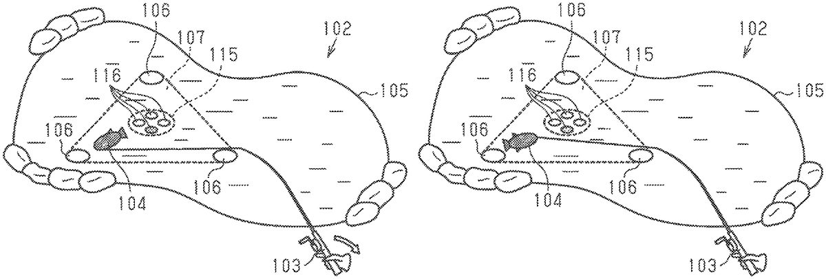
It is assumed inFIGS.18A and18Bthat the control unit31of the game processing device30has detected the intervention operation of the controller20while the moving object104moves to the outer side of the movement range107. In this case, the control unit31uses the first method to change the movement direction of the moving object. In the first method, the control unit31randomly selects a subsequent movement target position116from a plurality of movement target positions116set for a central area115of the movement range107of the moving object104.
In this case, the control unit31changes the size of the central area115in which the movement target positions116are set based on the type of the moving object104, the type of the item103(fishing rod) associated with the intervention operation of the controller20, and the like.
For example, for a moving object104having a high degree of rarity, the central area115is large. This can increase the difficulty for catching the moving object104.
Further, it is assumed inFIGS.18C and18Dthat the control unit31has detected the intervention operation of the controller20while the moving object104moves to the inner side of the movement range107. In this case, the control unit31uses the second method to change the movement direction of the moving object. In the second method, the control unit31sets, as a subsequent movement target position117, a position where the direction of the intervention operation of the controller20intersects an outer edge of the movement range107of the moving object104. That is, the control unit31causes the direction of the intervention operation of the controller20to match the changed movement direction of the moving object.
As described above, the third embodiment has the following advantage in addition to the advantages described in the first embodiment.
(19) in the third embodiment, the changed movement direction of the moving object104is determined based on the relative positional relationship of the direction of the intervention operation of the controller20and the movement range107of the moving object104. Thus, the movement direction of the moving object104can be changed to various directions by the intervention operation of the controller20.
Each of the above embodiments may be modified as described below.
In each of the above embodiments, the initial position for the avatar108is set in advance at a plurality of positions in the game field102. The method for setting the initial position for the avatar108is not limited to the advanced setting. For example, if the game field102is selected by a player, the control unit31may determine the movement range107of the moving object104in the game field102and arrange the initial position for the avatar108at any proximate position.
In each of the above embodiments, the type of the moving object104is associated with the game field102in advance. The method for selecting the type of the moving object104is not limited to the advanced setting. For example, if the game field102is selected by a player, the control unit31may set the initial position for the avatar108in the game field102and select the type of the moving object104moving in the game field102based on the set position of the avatar108.
In each of the above embodiments, the movement change timing of the moving object104is set at predetermined time intervals. The method for determining the movement change timing is not limited to the predetermined time intervals. For example, the control unit31may set, as the movement change timing of the moving object104, a timing at which the moving object104reaches a predetermined movement target position106.
In each of the above embodiments, a movement probability is set for each of the movement target positions106of the moving object104in advance, and a subsequent movement target position106of the moving object104is randomly selected based on the movement probability. The method for randomly selecting the movement target position106is not limited to a method based on the movement probability. For example, the control unit31may randomly select a subsequent movement target position106from a plurality of movement target positions106corresponding to the moving object104.
In each of the above embodiments, the arrangement, number, and movement probability of the movement target positions106are set in advance in association with the game field102for each of the types of the moving object104. The method for setting the arrangement, number, and movement probability of the movement target positions106corresponding to the type of the moving object104is not limited to the advanced setting. For example, the control unit31may change the arrangement, number, and movement probability of the movement target positions106of the moving object104in correspondence with the progress of the game.
In each of the above embodiments, the position of the item109in the game field102is determined based on the speed or acceleration of the operation of the controller20in the first direction. Instead, the position of the item109in the game field102may be determined based on an operation time of the operation of the controller20in the first direction. For example, the control unit31detects the direction and acceleration of the swing-down operation of the controller20and calculates, as the operation time of the operation of the controller20in the first direction, a required time from when the operation starts to when the operation ends. The position of the item109in the game field102is determined based on the calculated operation time. In this case, as the operation time of the controller20in the first direction becomes longer, the control unit31determines the position of the item109at a farther position as viewed from the viewpoint of the player.
In each of the above embodiments, if the operation of the controller20in the first direction is detected, a position lying on the extension line of the controller20in the first direction as viewed from the viewpoint of the player is determined as the position of the item109. Instead, regardless of the operation direction of the controller20, a position lying on the extension line in the direction of the attention position of the player may be determined as the position of the item109. In this case, the control unit31determines an attention direction of the player in the HMD10and arranges the item109on the coordinates in the attention direction in the virtual space. Further, the position of the item109in the game field102may be determined by taking into account both the direction of the operation of the controller20and the direction of the attention position of the player.
In each of the above embodiments, the operation in the first direction (casting) is the swing-down operation of the controller20, and the operation in the second direction (cancelling) is the swing-up operation of the controller20. Instead, the operation performed in the first direction may be the operation that swings up and swings down the controller20, and the operation performed in the second direction may be the operation that swings up the controller20. Alternatively, the operation performed in the second direction may be operation that swings and/or turns the controller20. These operations can be changed in correspondence with the configuration of the controller20. For example, when the controller20includes a touch panel, the first operation may be a swipe operation or a flick operation performed on the touch panel, and the second operation may be the swing-up operation of the controller20.
In each of the above embodiments, the first operation is the tap operation performed on the determination button, and the second operation is the swing-up operation of the controller20. Instead, the first operation and the second operation may be the swing-up operation of the controller20, and the operation amount of the second operation may be larger than the operation amount of the first operation. Alternatively, the first operation and the second operation may be the swing-up operation of the controller20, and the lower limit value of the operation speed for performing the second operation may be larger than the lower limit value of the operation speed for performing the first operation. Further, the first operation and the second operation may be changed in correspondence with the configuration of the controller20. For example, when the controller20includes a touch panel, the first operation may be a swipe operation or a flick operation performed on the touch panel, and the second operation may be the swing-up operation of the controller20.
In each of the above embodiments, the battle circle ill indicating the validity of the first operation of the controller20is displayed during the execution of the battle mode as an index of the progress state of the game until the second operation of the controller20is valid. In this case, the index of the progress state of the game until the second operation of the controller20is valid may be displayed separately from the display of the battle circle111. For example, the control unit31changes the initial value of a health gauge of the moving object104that is temporarily stored in the memory based on an operation state of the controller20. The health gauge of the moving object104is displayed in an upper area of the game field102in addition to the battle circle111.
In the second embodiment, the count value of the first operation of the controller20is calculated without taking into account the number of invalid first operations of the controller20. Instead, the count value of the first operation of the controller20may be calculated taking into account the number of invalid first operations of the controller20. For example, the control unit31calculates, as the count value of the first operation of the controller20, the value obtained by subtracting the number of invalid first operations of the controller20from the number of valid first operations of the controller20.
In the second embodiment, the number of valid first operations of the controller20is calculated as the count value of the first operation of the controller20. That is, the count value of the first operation of the controller20is calculated in the same manner for each area of the battle circle111if the first operation of the controller20is valid. Instead, the increment amount of the count value if the first operation of the controller20is valid may be separately set for each area of the battle circle111.
Further, if the first operation of the controller20is valid, the increment amount of the count value may be separately determined for each type of the moving object104, each type of the item103(fishing rod) associated with the first operation of the controller20, and the like.
For example, a small increment amount of the count value may be set for a moving object104having a high degree of rarity if the first operation of the controller20is valid. More specifically, the memory holds a table or a function to determine the increment amount of the count value (increment amount determination information) for each type of the moving object104. The increment amount corresponding to the difficulty for catching is set to the increment amount determination information. The control unit31determines the increment amount based on a moving object104that is subject to catching. Thus, the difficulty for catching the moving object104can be adjusted by, for example, setting a smaller increment amount as the degree of rarity becomes higher.
In the first and third embodiments, if the first operation of the controller20is valid, the contraction amount of the battle circle111is determined for each area of the battle circle111. The method for determining the contraction amount of the battle circle111is not limited to the method for determining the amount for each area. For example, the control unit31may set the same contraction amount of the battle circle111if the first operation of the controller20is valid without dividing the battle circle111into a plurality of areas.
In the first and third embodiments, the battle circle111is enlarged if the first operation of the controller20is invalid. The method for changing the battle circle111is not limited to the method for enlarging the battle circle111in correspondence with the validity of the first operation. For example, even if the first operation of the controller20is invalid, the control unit31may skip the process for enlarging the battle circle111.
In the first and third embodiments, the change amount of the battle circle111corresponding to the validity of the first operation of the controller20is determined based on the type of the moving object104, the type of the item103(fishing rod) associated with the first operation of the controller20, and the like. The method for determining the change amount of the battle circle111is not limited to the method based on the type of the moving object104, the type of the item103, and the like. For example, the control unit31may set the same change amount of the battle circle111corresponding to the validity of the first operation of the controller20.
In each of the above embodiments, the size of the battle circle111is changed as time elapses. The method for changing the battle circle111is not limited to the method based on the elapsed time. For example, regardless of the elapsed time, the control unit31may determine the size of the battle circle111based only on the validity of the first operation of the controller20.
In the first and third embodiments, the battle mode ends if the size of the battle circle111reaches the outer circle113. The condition for ending the battle mode is not limited to such a condition. For example, the control unit31may determine, as the ending condition, that the elapsed time of the battle mode has reached a predetermined time and that the number of invalid first operations of the controller20has reached a predetermined value.
In each of the above embodiments, it is determined whether or not the first operation of the controller20is started based on the affinity of the type of the moving object104and the type of the item109associated with the first operation of the controller20. The condition for determining whether or not the first operation of the controller20is started is not limited to such a condition. For example, the control unit31may use, as the determination condition, the affinity of the game field102and the type of the item109(lure) associated with the first operation of the controller20. In this case, for example, the type of the item109that can be used in the game field102is recorded in the item information40.
In each of the above embodiments, the second operation of the controller20is determined as being valid under the condition that the reference time has not elapsed from when the size of the battle circle111reached the central circle112. The condition for determining that the second operation of the controller20is valid is not limited to such a condition. For example, the control unit31may adopt a condition that the moving object104has not moved out of the battle circle111. In addition, if the size of the battle circle111reaches the central circle112, the control unit31may determine that the second operation of the controller20is valid until the second operation of the controller20is detected.
In each of the above embodiments, if the intervention operation of the controller20is detected, the movement direction of the moving object104can be changed to the outside of the movement range107of the moving object104, which is set based on the movement range information. Instead, the control unit31may limit the movement direction of the moving object104with the intervention operation of the controller20to the inside of the movement range107.
In each of the above embodiments, the changed movement direction of the moving object104is determined based on the direction of the intervention operation of the controller20. In addition to the direction of the intervention operation of the controller20, the movement direction of the moving object prior to changing may be further taken into account to determine the changed movement direction of the moving object104. For example, the control unit31generates vector components in the direction of the intervention operation of the controller20and vector components in the movement direction of the moving object104prior to changing to determine the direction of the combined vector as the changed movement direction of the moving object104.
In the third embodiment, a subsequent movement target position116of the moving object104is randomly selected from a plurality of movement target positions116set for the central area115if the direction of the intervention operation of the controller20is oriented toward the inside of the movement range107of the moving object104. The method for determining the movement target position116is not limited to such a method. For example, the movement probability of the moving object104is set in advance for each movement target position116, which is set in the central area115. The control unit31randomly selects a subsequent movement target position116of the moving object104based on the movement probability.
Further, the control unit31may randomly select a subsequent movement target position116of the moving object104based on the relative positional relationship of the direction of the intervention operation of the controller20and the movement target positions116set for the central area115. For example, the control unit31sets an extension line in the direction of the intervention operation of the controller20as viewed from the position of the moving object104. The control unit31determines a movement target position116that is most proximate to the extension line as a subsequent movement target position116of the moving object104.
Additionally, the control unit31may determine a predetermined position in the central area115, such as the center point of the movement range107of the moving object104, as a subsequent movement target position of the moving object104when the intervention operation of the controller20is performed.
In each of the above embodiments, it is determined whether or not the intervention operation of the controller20has been successfully performed based on the type of the moving object104, the type of the item103(fishing rod) associated with the intervention operation of the controller20, and the like. The condition for determining whether or not the intervention operation of the controller20has been successfully performed is not limited to such a condition. For example, the control unit31may use, as a condition, the affinity of the game field102and the item103(fishing rod) associated with the intervention operation of the controller20, the affinity of the moving object104and the item103(fishing rod) associated with the intervention operation of the controller20, and the like. Further, if the intervention operation of the controller20is detected, the control unit31may cause the intervention operation of the controller20to succeed without setting a precondition and randomly determine whether or not the intervention operation of the controller20has been successfully performed.
In each of the above embodiments, the changed movement direction of the moving object104is determined based on the type of the moving object104, the type of the item103associated with the intervention operation of the controller20, and the like. The condition for determining the changed movement direction of the moving object104is not limited to such a condition. For example, the control unit31may use, as a condition, the affinity of the game field102and the item103(fishing rod) associated with the intervention operation of the controller20, the affinity of the moving object104and the item103(fishing rod) associated with the intervention operation of the controller20, and the like. Further, if the intervention operation of the controller20is detected, the control unit31may determine the same changed movement direction for the moving object104based on the direction of the intervention operation of the controller20.
In each of the above embodiments, when the movement direction of the moving object104is changed by the intervention operation of the controller20, intervals are set to the timing for changing the movement direction of the moving object104. Instead, the control unit31does not have to set intervals to the timing for changing the movement direction of the moving object104by the intervention operation of the controller20. In this case, even when changing the movement direction of the moving object104by the intervention operation of the controller20, the control unit31continues to accept the intervention operation of the controller20.
Further, the lengths of the intervals may be variable based on the type of the moving object104, the type of the item103(fishing rod) associated with the intervention operation of the controller20, and the like. In this case, the control unit31maintains information used to set intervals in correspondence with the type of the moving object104, the type of the item103, and the like.
For example, for a moving object104having a high degree of rarity, long intervals may be set. This can increase the difficulty for catching the moving object104.
In each of the above embodiments, the case in which a game played by two players is presented is described. Instead, a game played by three players or more may be presented. In this case, the HMDs10that are equal in number to the players are connected to the game processing device30.
In each of the above embodiments, the game processing device30determines the position and orientation of the head of a player. Instead, the HMD controller11may obtain the position and orientation of the head based on a detection signal of the sensor12. As another option, the HMD10may be a device such as a smartphone including a touch panel and a communication unit and may include the control unit31. In this case, the control unit31of the device such as a smartphone consecutively obtains information via a network from a server that records, for example, the game field information37to cause the game to be executed. When multiple persons play the game, the HMDs10may communicate with one another and communicate via the server. Thus, the HMD10can have at least part of the functions of the game processing device30described in each of the above embodiments.
In each of the above embodiments, the HMD10determines the position and orientation of the head of a player. Instead, the HMD10may determine the position and orientation of a section of the player other than the head, for example, the position of an iris.
In each of the above embodiments, the game presented to a player is applied to a virtual reality game that displays a three-dimensional image on the display14. Instead, the above game may be a game that displays a two-dimensional image on the display. In this case, the HMD10may be changed to an installation-type display. The player operates the controller20while checking a display on the display and performs operation such as casting.
In each of the above embodiments, a plurality of players view a moving object in the virtual space from the perspective of the avatar108corresponding to each player. Instead, each player may be able to switch the viewpoint. For example, each player may view a moving object in the virtual space from a bird's-eye view at the rear of the avatar as well as from the viewpoint of the avatar. More specifically, in the virtual space, the control unit31sets, for the avatar, a viewpoint at a far side of the game field and outputs an image from this viewpoint to the HMD10. In this case, for example, each player may select a viewpoint before the game starts or may be able to change a viewpoint while playing the game.
The game device30may execute game control using the position of the game device30. In this aspect, as shown inFIG.19, the game device30includes an absolute position acquisition unit43. The absolute position acquisition unit43acquires position information transmitted from a satellite positioning system such as a global positioning system (GPS). The control unit31of the game device30determines an absolute position of the game processing device30based on the information acquired by the absolute position acquisition unit43. Further, the memory unit32of the game device30stores game map data. The map data stores a region or a point where the game is executable in association with the absolute position. The region or the point where the game is executable is, for example, a region or a point where a fishing game is executable. The region or the point where the fishing game is executable may be determined using, for example, an old map. Referring to the acquired absolute position and the map data, the control unit31determines whether or not the position of the game device30is the region or the point where the fishing game is executable. If the control unit31determines that the position of the game device30is not the region or the point where the fishing game is executable, the control unit31does not set the fishing game to an executable state. For example, the display14of the HMD10does not display the region or the point such as sea, pond, and river where the fishing game is executable. If the control unit31determines that the position of the game device30is the region or the point where the fishing game is executable, the control unit31sets the fishing game to an executable state. For example, the display14of the HMD10displays the region or the point such as sea, pond, and river where the fishing game is executable.
In each of the above embodiments, a fishing game is provided as an example of a game. Instead, the present disclosure may be applied to other games. That is, the present disclosure may be applied to any game in which a player controls the movement direction of a moving object in a game field by an input operation of a controller.
Claims
- A non-transitory computer-readable medium that stores instructions which, when executed by a processor, cause the processor to: move a moving object in a first direction within a movement range set in a game field;detect that, during movement of the moving object in the first direction, a controller is operated in an operation direction that is different from the first direction;responsive to the operation direction being oriented toward an inside of the movement range, terminate the movement of the moving object in the first direction and move the moving object in a second direction that is randomly determined;and responsive to the operation direction being oriented toward an outer side of the movement range, terminate the movement of the moving object in the first direction and move the moving object in the operation direction.
- The non-transitory computer-readable medium according to claim 1, wherein another movement range of another moving object is set based on movement range information that indicates the another movement range of the another moving object, and the second direction includes a direction in which the moving object moves to a position located outside the another movement range of the another moving object.
- The non-transitory computer-readable medium according to claim 1, wherein the instructions, when executed by the processor, cause the processor to determine whether or not a direction in which another moving object is moved can be changed based on a type of the another moving object.
- The non-transitory computer-readable medium according to claim 3, wherein the instructions, when executed by the processor, cause the processor to responsive to determining that the direction in which the another moving object is moved can be changed, change the direction in which the another moving object is moved to a third direction, wherein a degree of matching the operation direction with the third direction for a moving object having a first degree of rarity is lower than a degree of matching the operation direction with the third direction for a moving object having a second degree of rarity that is lower than the first degree of rarity.
- The non-transitory computer-readable medium according to claim 1, wherein the instructions, when executed by the processor, cause the processor to determine whether or not a direction in which another moving object is moved can be changed based on a type of an item associated with operation of the controller.
- The non-transitory computer-readable medium according to claim 1, wherein the second direction is determined based on a relative positional relationship of operation direction and another movement range of the moving object based on a position of the moving object.
- The non-transitory computer-readable medium according to claim 1, wherein a size of a central area within the movement range is determined based on a type of another moving object.
- The non-transitory computer-readable medium according to claim 1, wherein the instructions, when executed by the processor, cause the processor to: maintain a direction in which another moving object is moved until a predetermined time elapses from when the direction is changed, and resume change of the direction in which the another moving object is moved when the predetermined time elapses.
- The non-transitory computer-readable medium according to claim 1, wherein the instructions, when executed by the processor, cause the processor to: start detecting that the controller is operated in a direction that is different from a direction in which another moving object is moved when the another moving object and an item associated with operation of the controller satisfy a predetermined start determination condition.
- The non-transitory computer-readable medium according to claim 1, wherein the instructions, when executed by the processor, cause the processor to: determine whether or not a direction in which another moving object is moved can be changed based on an operation state of the another moving object.
- The non-transitory computer-readable medium according to claim 1, wherein the instructions, when executed by the processor, cause the processor to: change a direction in which the moving object is moved at a predetermined timing.
- A method, comprising: moving, by circuitry, a moving object in a first direction within a movement range set in a game field;detecting that, during movement of the moving object in the first direction, a controller is operated in an operation direction that is different from the first direction;responsive to the operation direction being oriented toward an inside of the movement range, terminating the movement of the moving object in the first direction and moving the moving object in a second direction that is randomly determined;and responsive to the operation direction being oriented toward an outer side of the movement range, terminating the movement of the moving object in the first direction and move the moving object in the operation direction.
- The method according to claim 12, further comprising: determining whether or not a direction in which another moving object is moved can be changed based on a type of the another moving object.
- The method according to claim 12, further comprising: determining whether or not a direction in which another moving object is moved can be changed based on a type of an item associated with operation of the controller.
- The method according to claim 12, wherein the second direction is determined based on a relative positional relationship of operation direction and another movement range of the moving object based on a position of the moving object.
- The method according to claim 12, further comprising: maintaining a direction in which another moving object is moved until a predetermined time elapses from when the direction is changed;and resuming change of the direction in which the another moving object is moved when the predetermined time elapses.
- The method according to claim 12, further comprising: starting detecting that the controller is operated in a direction that is different from a direction in which another moving object is moved when the another moving object and an item associated with operation of the controller satisfy a predetermined start determination condition.
- The method according to claim 12, further comprising: determining whether or not a direction in which another moving object is moved can be changed based on an operation state of the another moving object.
- A device, comprising: circuitry configured to: move a moving object in a first direction within a movement range set in a game field, detect that, during movement of the moving object in the first direction, a controller is operated in an operation direction that is different from the first direction, responsive to the operation direction being oriented toward an inside of the movement range, terminate the movement of the moving object in the first direction and move the moving object in a second direction that is randomly determined, and responsive to the operation direction being oriented toward an outer side of the movement range, terminate the movement of the moving object in the first direction and move the moving object in the operation direction.
Disclaimer: Data collected from the USPTO and may be malformed, incomplete, and/or otherwise inaccurate.