U.S. Pat. No. 11,752,440
Grip for Video Game Controller
Issue DateMarch 5, 2021
Illustrative Figure
Abstract
A grip for a video game controller has a body with a longitudinal axis, a base section, a finger grip section, and a palm support section, the body defining a cavity oriented along the longitudinal axis cavity therein, the cavity being sized to receive the hand-hold portion of a video game controller therein. The grip functions as a stand to hold the controller upright when placed on a flat surface and provides comfortable support to the user's fingers, palm and thumb pad during play.
Description
DETAILED DESCRIPTION OF THE PREFERRED EMBODIMENT AND OPERATION OF THE INVENTION Various exemplary embodiments of the present disclosure are described below. Use of the term “exemplary” means illustrative or buy way of example only, and any reference herein to “the invention” is not intended to restrict or limit the invention to exact features or step of any one or more of the exemplary embodiments disclosed in the present specification. References to “exemplary embodiment”, “one embodiment”, “an embodiment”, “various embodiments”, and the like may indicate that the embodiment(s) of the invention so described may include a particular feature, structure, or characteristic, but not every embodiment necessarily incudes the particular feature, structure, or characteristic. Further, repeated use of the phrase “in one embodiment”, “in an exemplary embodiment”, or “in an alternative embodiment” do not necessarily refer to the same embodiment, although they may. It is also noted that terms like “preferably”, “commonly”, and “typically” are not utilized herein to limit the scope of the invention or to imply that certain features are critical, essential, or even important to the structure or function of the invention. Rather, these terms are merely intended to highlight alternative or additional features that may or may not be utilized in a particular embodiment of the present invention. The present invention is described more fully hereinafter with reference to the accompanying figures, in which one or more exemplary embodiments of the invention are shown. Like numbers used herein refer to like elements throughout. The invention may, however, be embodied in many different forms and should not be construed as limited to the embodiments set forth herein; rather, these embodiments are provided so that this disclosure will be operative, enabling, and complete. Accordingly, the particular arrangements disclosed are meant to be illustrative only and not limited as to the ...
DETAILED DESCRIPTION OF THE PREFERRED EMBODIMENT AND OPERATION OF THE INVENTION
Various exemplary embodiments of the present disclosure are described below. Use of the term “exemplary” means illustrative or buy way of example only, and any reference herein to “the invention” is not intended to restrict or limit the invention to exact features or step of any one or more of the exemplary embodiments disclosed in the present specification. References to “exemplary embodiment”, “one embodiment”, “an embodiment”, “various embodiments”, and the like may indicate that the embodiment(s) of the invention so described may include a particular feature, structure, or characteristic, but not every embodiment necessarily incudes the particular feature, structure, or characteristic. Further, repeated use of the phrase “in one embodiment”, “in an exemplary embodiment”, or “in an alternative embodiment” do not necessarily refer to the same embodiment, although they may.
It is also noted that terms like “preferably”, “commonly”, and “typically” are not utilized herein to limit the scope of the invention or to imply that certain features are critical, essential, or even important to the structure or function of the invention. Rather, these terms are merely intended to highlight alternative or additional features that may or may not be utilized in a particular embodiment of the present invention.
The present invention is described more fully hereinafter with reference to the accompanying figures, in which one or more exemplary embodiments of the invention are shown. Like numbers used herein refer to like elements throughout. The invention may, however, be embodied in many different forms and should not be construed as limited to the embodiments set forth herein; rather, these embodiments are provided so that this disclosure will be operative, enabling, and complete. Accordingly, the particular arrangements disclosed are meant to be illustrative only and not limited as to the scope of the invention, and any and all equivalents thereof. Moreover, many embodiments such as adaptations, variations, modifications, and equivalent arrangements will be implicitly disclosed by the embodiments described herein and fall within the scope of the instant invention.
Although specific terms are employed herein, they are used in a generic and descriptive sense only and not for the purposes of limitation. Unless otherwise expressly defined herein, such terms are intended to be given their broad, ordinary, and customary meaning not inconsistent with that applicable in the relevant industry ad without restriction to any specific embodiment hereinafter described. As used herein, the article “a” is intended to include one or more items. Where only one item is intended, the terms “one and only one”, “single”, or similar language is used. When used herein to join a list of items, the term “or” denotes at least one of the items, but does not exclude a plurality of items of the list.
For exemplary methods or processes of the invention, the sequence and/or arrangement of steps described herein are illustrative and not restrictive. Accordingly, it should be understood that, although steps of various processes or methods may be shown and described as being in a sequence or temporal arrangement, the steps of any such processes or methods are not limited to being carried out in any particular sequence or arrangement, absent an indication otherwise. Indeed, the steps in such processes or methods generally may be carried out in various different sequences and arrangements while still falling within the scope of the present invention.
Additionally, any references to advantages, benefits, unexpected results, or operability of the present invention are not intended as an affirmation that the invention has previously been reduced to practice or that any testing has been performed. Likewise, unless stated otherwise, use of verbs in the past tense (present perfect or preterit) is not intended to indicate or imply that the invention has previously been reduced to practice or that any testing has been performed.
For a better understanding of the invention and its use, turning now to the drawings,FIGS.1-11illustrate grips for use with a video game controller. The ergonomically advantageous grip provides additional comfort and tactile feel for the user, particularly during extended play, resulting in less hand fatigue, better control of the controller, and more enjoyable play. The grip further can be used as a stand to store the controller upright when placed on a flat surface.
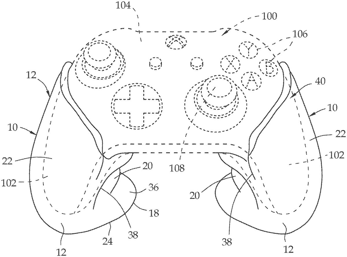
Referring toFIGS.1-6, illustrated therein is a controller100of the type typically used for a first gaming system, for example an Xbox gaming system. The controller100(illustrated in phantom) has a pair of hand hold sections102, one disposed on opposing lateral sides of a central portion104containing a variety of buttons106and joysticks108used for play. Preferred grip10fits over each of the respective hand hold sections102of the controller. The embodiment of the grip10shown inFIG.1corresponds to the embodiment illustrated inFIGS.2-6, whereas the embodiment ofFIGS.7-11is adapted for use with a controller (not shown) for a second gaming system, for example a PlayStation 4 gaming system.
As is readily apparent when viewingFIG.1, the grip10of the invention preferably changes the overall shape and configuration of the hand hold portions102of the controller. This differs from prior art devices which merely add an additional layer of softer material to the controller, but did nothing to change the ergonomic or topographic features of the hand hold sections102, specifically as it relates to finger position and wrist orientation during use. When using one or more embodiment(s) of grip10, the user's fingers are less constricted about hand hold sections102, increasing blood flow to the extremities and reducing joint and muscle fatigue over time. Additionally, or in the alternative, base section18permits the user to rest the controller on a flat surface during use, alleviating weight in the user's hands and/or unnecessary rotation of the wrist(s) for extended periods of time.
The preferred embodiment of grip10has a unitary body12having a longitudinal axis14. Body12preferably defines a cavity16that is oriented, and extends along the longitudinal axis14. The cavity16is configured (i.e. sized and shaped) to closely receive therein a hand hold portion102of the controller100. The term “hand hold portion of the controller” is used herein to identify that portion of a gaming controller that the user normally grips in the palm with the hands during play, but may not include the portion(s) of the control that include one or more buttons106and/or joystick(s)108.
The body12may include a base section18, a finger grip section20, and a palm support section22. When attached to the controller100, the grip10allows the controller100to remain upright when placed on a flat surface, as best seen inFIG.1. For this reason, it is desirable that the base section18defines a generally flat bottom surface24. In addition, it is preferred that bottom surface24of base section18has enough surface area to provide a stable support for the controller. It may also be advantageous to create the base section18with greater mass and/or a reinforced construction to provide the desired rigidity to the base section18. Additionally, or in the alternative, body12may define a larger, wider, longer, or otherwise more pronounced lip area36as described in further detail below. Additionally, or in the alternative, embodiments of body12may define one or more recessed grooves, particularly about the exterior periphery of one or more aspects of grip10.
The finger grip section20of grip10preferably defines a plurality of spaced-apart ridges26,28, defining valleys30,32,34in the areas between the ridges26,28. The ridges26,28and valleys30,32,34defining spaces to accommodate the fingers of the user when holding the grip10. In operating a gaming controller, the thumb and index finger of the user are normally required to operate the various buttons106and joy sticks108on the controller to control the game action, while the remaining fingers are not used. Thus, the ridges26,28and valleys30,32on the finger grip section20will preferably be configured to accommodate the middle, ring and little fingers on the hand (not shown). For those times when the index finger is not needed for play, a valley34may be provided to accommodate the index finger. In the preferred embodiment, the finger grip section20, and more preferably ridge28terminates at vertical plane41which may extend parallel to longitudinal axis14.
In one or more embodiments, the base section18may have an extended forward protrusion19(FIG.5) defining a lip protrusion33having upper and lower surfaces37,35respectively that extend away from a flat surface, said extended forward protrusion19and lip protrusion33forming a lip area36(most pronounced in the embodiments ofFIGS.1-6) which can further support the fingers of the user during play and help prevent the user's hand, particularly a little finger of the user, from displacing in one or both of a lateral and longitudinal direction(s) from a controller. Additionally, or in the alternative, the extended forward protrusion19and lip protrusion33forming lip area36is configured to facilitate a user “rolling” the controller slightly forward, while the base section18is placed, for example, on the leg of a user. As illustrated in one or more preferred embodiments of grip10and/or210, lip area36,236extends beyond vertical plane41. This may allow the user to change the angle of the controller and/or permit adjustment of a wrist of the user during gameplay for maximum comfort.
Palm support section22is located generally opposite the finger grip section20of grip10. When holding the controller100, the user's hand is normally curved into a loose first around the grip10. When curved into a loose fist, the palm of the hand forms a concave surface. To best conform to the shape of the hand during use of the controller, the palm support section22has a gentle convex outer surface that corresponds to the curved concave surface of the palm.
The palm support surface22is contoured to be narrowest near the base section18and widest at the top end40of body12, remote from the base section18, providing body12with an overall shape and appearance of a truncated cone. The wider portions of palm support section22at the top end40of body12provide support for the thumb pad as the user's hand wraps about the grip10. The configuration of the palm support section22forms a ridgeline38(FIG.6) which conforms to the point where the palm and thumb pad of the user joins the wrist, commonly known as the “heel” of the hand. The ridgeline38defines a boundary between the palm support section22and the finger grip section20. The grip10thus supports the user's entire hand—palm, fingers, thumb pad—while still allowing unrestricted movement of the thumb and index finger to operate the various buttons106and joy sticks108on the controller100.
With reference now being made to the embodiments ofFIGS.7-11, the grip210shown therein is configured to fit the controller for a second gaming system, for example the PlayStation 4 game system and, apart from cosmetic differences resulting from the different shapes of the respective controllers, is essentially the same as the grip10shown inFIGS.1-6.
The grip210has a unitary body212having a longitudinal axis214. Body212may define a cavity216that is oriented along the longitudinal axis214. The cavity216is configured (i.e. sized and shaped) to closely receive therein a hand hold portion of the controller of the second gaming system.
The body212has a base section218, a finger grip section220, and a palm support section222. When attached to the controller, the base section218permits the controller to remain upright when placed on a flat surface. For this reason, it is desirable that the base section218has a generally flat bottom surface224. In addition, it is preferred that bottom surface224of base section218has enough surface area to provide a stable support for the controller. It may also be advantageous to create the base section218with greater mass and/or a reinforced construction to provide the desired rigidity to the base section218. Additionally, or in the alternative, body212may define a larger, wider, longer, or otherwise more pronounced lip area236as described in further detail below. Additionally, or in the alternative, embodiments of body212may define one or more recessed grooves, particularly about the exterior periphery of one or more aspects of grip210.
The finger grip section220of grip210may define a plurality of spaced-apart ridges226,228, defining valleys230,232,234in the areas between the ridges226,228as seen inFIGS.8and9. The ridges226,228and valleys230,232,234defining spaces to accommodate the fingers of the user when holding the grip210. In operating a gaming controller, the thumb and index finger of the user are normally required to operate the various buttons on the controller to control the game action, while the remaining fingers are not used. Thus, the ridges226,228and valley230,232on the finger section220will preferably be configured to accommodate the middle, ring and little fingers on the hand. For those times when the index finger is not needed for play, a valley234may be provided to accommodate the index finger.
In the embodiment, the base section218may have an extended forward protrusion defining a lip protrusion having upper and lower surfaces that extend away from a flat surface, said extended forward protrusion and lip protrusion forming a lip area236which can further support the fingers of the user during play and help prevent the user's hand, particularly a little finger of the user, from displacing in one or both of a lateral and longitudinal direction(s) from a controller. The extended lip area236also increases the surface area of base section218, which helps in providing a stable stand when the controller is to be stored upright. Additionally, or in the alternative, the extended forward protrusion and lip protrusion forming lip area236is configured to facilitate a user “rolling” the controller slightly forward, while the base section218is placed, for example, on the leg of a user. This may allow the user to change the angle of the controller and/or permit adjustment of a wrist of the user during gameplay for maximum comfort.
Palm support section222is located generally opposite the finger grip section220of grip210. When holding the controller, the user's hand is normally curved into a loose first around the grip10. When curved into a loose fist, the palm of the hand forms a concave surface. To best conform to the shape of the hand during use of the controller, the palm support section222has a gentle convex outer surface that corresponds to the curved concave surface of the palm.
The palm support surface222is contoured to be narrowest near the base section218and widest at the top end240of body212, remote from the base section218, providing body212with an overall shape and appearance of a truncated cone. The wider portions of palm support section222at the top end240of body212provide support for the thumb pad as the user's hand wraps about the grip210. The configuration of the palm support section222forms a ridgeline238which conforms to the heel of the hand (i.e., the point where the palm and thumb pad meet the wrist). The grip210thus supports the user's entire hand—palm, fingers, thumb pad—while still allowing unrestricted movement of the thumb and index finger to operate the various buttons and joy sticks on the controller.
While the grips10,210can be made from several different materials, it is preferred to use a material that offers a pleasant tactile sensation for the user and that is soft and comfortable to hold. Most preferred are natural or synthetic polymers and blends thereof, such as silicone rubber blends. The grips10,210can be made by any suitable process consistent with the materials selected to make the grips, such as casting, molding, 3D printing, etc.
In the drawings and specification there has been set forth preferred embodiments of the invention, and although specific terms have been employed, they are used in a generic and descriptive sense only and not for purposes of limitation, the scope of the invention being defined in the claims. Modifications and alternatives that may suggest themselves to those skilled in the art upon reading the foregoing disclosure are intended to be considered within the scope of the invention.
Claims
- A grip for a video game controller of a type having hand hold sections, the grip comprising a unitary body including a finger grip section defining a plurality of spaced-apart ridges defining valleys between the ridges, the valleys and ridges defining spaces sized to receive one or more fingers of a user;and a base section, the unitary body defining a longitudinal axis and the finger grip section terminating at a plane parallel to the longitudinal axis;said unitary body forming a cavity that is oriented along the longitudinal axis;said cavity is sized and shaped to receive therein a hand hold section of the video game controller;the base section configured to serve as a stand to permit the video game controller to remain upright when placed on a flat surface, the base section defining an extended forward protrusion extending beyond the plane parallel to the longitudinal axis, the extended forward protrusion defining a lip protrusion positioned distal the longitudinal axis and beyond the plane parallel to the longitudinal axis, a portion of the extended forward protrusion extending beyond the plane parallel to the longitudinal axis and the lip protrusion further defining upper and lower surfaces that each extend upwardly and away from the flat surface, said extended forward protrusion and lip protrusion forming a lip area to support fingers of a user and prevent a little finger of the user from displacing in one or both of a lateral and longitudinal direction(s) from the video game controller.
- The grip of claim 1, wherein the base section defines a flat bottom surface.
- The grip of claim 1, wherein the body further comprises a palm support section.
- The grip of claim 1, wherein the body further comprises a palm support section and the base section having a flat bottom surface.
- The grip of claim 1, wherein the body further comprises a palm support section;the base section having a flat bottom surface;wherein the palm support section is positioned opposite the finger grip section and wherein the palm support section has a convex outer surface.
- The grip of claim 1, wherein the body further comprises a palm support section;the palm support section defining a shape that is narrowest adjacent to the base section and widest at a top end of the body, said top end being remote from the base section.
- The grip of claim 1, wherein the body further comprises a palm support section;the palm support section defining a shape that is narrowest adjacent to the base section and widest at a top end of the body, said top end being remote from the base section;wherein said palm support section further comprises a ridgeline defining a boundary between the finger grip section and the palm support section.
- The grip of claim 1, comprising a silicone rubber material.
- The grip of claim 1, wherein the base section is more reinforced relative to the unitary body.
- The grip of claim 1, wherein the grip is formed from a natural or synthetic polymeric material.
- The grip of claim 1, wherein the body further comprises a palm support section;wherein the base section is more reinforced relative to the unitary body and has a generally flat bottom surface;wherein the palm support section is positioned opposite the finger grip section;wherein the palm support section has a convex outer surface;the palm support section defines a shape that is narrowest adjacent to the base section and widest at a top end of the body, said top end being remote from the base section;wherein said body defines a truncated cone shape;wherein said palm support section further comprises a ridgeline defining a boundary between the finger grip section and the palm support section.
- The grip of claim 1, wherein the body further comprises a palm support section;wherein the base section is more reinforced relative to the unitary body and has a flat bottom surface;said finger grip section having a plurality of spaced-apart ridges defining valleys between the ridges, the valleys and ridges defining spaces sized to receive one or more fingers of a user;wherein the palm support section is positioned opposite the finger grip section;wherein the palm support section has a convex outer surface;the palm support section defines a shape that is narrowest adjacent to the base section and widest at a top end of the body, said top end being remote from the base section;wherein said body defines a truncated cone shape;wherein said palm support section further comprises a ridgeline defining a boundary between the finger grip section and the palm support section.
- A grip for a video game controller of a type having hand hold sections, the grip comprising a unitary body including a finger grip section and a base section, the unitary body defining a longitudinal axis and the finger grip section terminating at a plane parallel to the longitudinal axis;said unitary body forming a cavity that is oriented along the longitudinal axis;said cavity is sized and shaped to receive therein a hand hold section of the video game controller therein;the base section configured to serve as a stand to permit the video game controller to remain upright when placed on a flat surface, the base section defining an extended forward protrusion extending beyond the plane parallel to the longitudinal axis the extended forward protrusion defining a lip protrusion positioned distal the longitudinal axis and beyond the plane parallel to the longitudinal axis, a portion of the extended forward protrusion extending beyond the plane parallel to the longitudinal axis and the lip protrusion further defining upper and lower surfaces that each extend upwardly and away from the flat surface, the lower surface continuous with the flat surface, said extended forward protrusion and lip protrusion forming a lip area to support fingers of a user and prevent a little finger of the user from displacing in one or both of a lateral and longitudinal direction(s) from the video game controller.
- The grip of claim 13, wherein the base section defines a flat bottom surface.
- The grip of claim 13, wherein the base section defines a flat bottom surface and said finger grip section having a plurality of spaced-apart ridges defining valleys between the ridges, the valleys and ridges defining spaces sized to receive one or more fingers of a user.
- The grip of claim 13, wherein the body further comprises a palm support section.
- The grip of claim 16, wherein the palm support section is positioned opposite the finger grip section and wherein the palm support section has a convex outer surface.
- The grip of claim 16, wherein the palm support section further comprises a ridgeline defining a boundary between the finger grip section and the palm support section.
Disclaimer: Data collected from the USPTO and may be malformed, incomplete, and/or otherwise inaccurate.