U.S. Pat. No. 11,738,260
A game controller with Dpad
AssigneeSHENZHEN ONEBITDO TECH CO., LTD.
Issue DateJuly 27, 2020
Illustrative Figure
Abstract
A cross button and a game controller with Dpad are provided. The cross button includes a button cap, a silicone pad, a circuit board and a controller. The circuit board is communicatively connected to the controller, and the silicone pad is located between the button cap and the circuit board. A first anti-mistouch pillar and four first trigger pillars are disposed on the silicone pad, and they are located on a side on the silicone pad close to the circuit board. The four first trigger pillars are evenly distributed on the silicone pad, and the first anti-mistouch pillar is located at a center of the four first trigger pillars. When all of the four first trigger pillars trigger signals, the controller controls a virtual button to trigger. A virtual button function of cross button is added without changing the original button, so the applicability of the cross button is enhanced.
Description
DESCRIPTION OF THE PREFERRED EMBODIMENTS To enable the above objects, features and advantages of the invention to be more apparent and easily understood, the specific embodiments of the invention will be further elaborated hereafter in connection with the drawings. With the continuous development of the game, the demand for multi-function of the handle is getting higher and higher, and the cross button is limited by the operation space and the number of buttons is limited, which may no longer meet the needs of users and affect the user experience. The inventor of the invention obtained the invention on long-term research. With reference toFIG.1, the invention provides a cross button, which includes a button cap100, a silicone pad200, a circuit board300and a controller, wherein the circuit board300is communicatively connected to the controller, and the silicone200pad is located between the button cap100and the circuit board300. A first anti-mistouch pillar210and four first trigger pillars220are disposed on the silicone pad200, and both the first anti-mistouch pillar210and the first trigger pillars220are located on a side on the silicone pad200close to the circuit board300. The four first trigger pillars220are evenly distributed on the silicone pad200, and the first anti-mistouch pillar210is located at a center of the four first trigger pillars220. When all of four first trigger pillars220trigger signals, the controller controls a virtual button to trigger. It should be noted that in the present embodiment, the button cap100, the silicone pad200and the circuit board300are arranged in order from top to bottom. The four first trigger pillars220are arranged in a cross shape, and the four first trigger pillars220are evenly distributed on the silicone pad200. Generally, distances between the first trigger pillars220and intersections of the cross are equal, and the first anti-mistouch pillar210is located at the center of the four first trigger pillars220, that is to say, the ...
DESCRIPTION OF THE PREFERRED EMBODIMENTS
To enable the above objects, features and advantages of the invention to be more apparent and easily understood, the specific embodiments of the invention will be further elaborated hereafter in connection with the drawings.
With the continuous development of the game, the demand for multi-function of the handle is getting higher and higher, and the cross button is limited by the operation space and the number of buttons is limited, which may no longer meet the needs of users and affect the user experience. The inventor of the invention obtained the invention on long-term research.
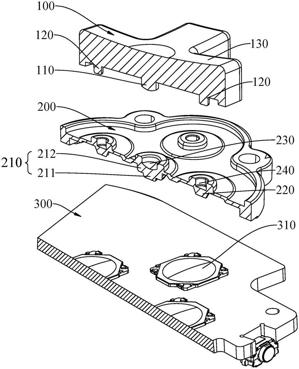
With reference toFIG.1, the invention provides a cross button, which includes a button cap100, a silicone pad200, a circuit board300and a controller, wherein the circuit board300is communicatively connected to the controller, and the silicone200pad is located between the button cap100and the circuit board300.
A first anti-mistouch pillar210and four first trigger pillars220are disposed on the silicone pad200, and both the first anti-mistouch pillar210and the first trigger pillars220are located on a side on the silicone pad200close to the circuit board300. The four first trigger pillars220are evenly distributed on the silicone pad200, and the first anti-mistouch pillar210is located at a center of the four first trigger pillars220.
When all of four first trigger pillars220trigger signals, the controller controls a virtual button to trigger.
It should be noted that in the present embodiment, the button cap100, the silicone pad200and the circuit board300are arranged in order from top to bottom. The four first trigger pillars220are arranged in a cross shape, and the four first trigger pillars220are evenly distributed on the silicone pad200. Generally, distances between the first trigger pillars220and intersections of the cross are equal, and the first anti-mistouch pillar210is located at the center of the four first trigger pillars220, that is to say, the first anti-mistouch pillar210is located at the intersection of the cross.
It should be noted that when the first trigger pillar220is pressed alone, the circuit board300is triggered to generate a corresponding button signal. Specifically, in some embodiments, four metal dome buttons310are disposed on the circuit board300, the metal dome buttons310are corresponding to the first trigger pillars220, and the depression of the first trigger pillars220drives the metal dome buttons310to trigger the circuit board300to generate a corresponding button signal.
As shown inFIGS.1to3, four pressing portions130are disposed on an upper surface of the button cap100, and the pressing portions130are disposed in a one-to-one correspondence with the first trigger pillars220. Taking one of the pressing portions130as an example: when the pressing portion130on the right is pressed, the first trigger pillar220located under the pressing portion130is compressed by force to drive the metal dome button310to press down and trigger the circuit board300to generate a corresponding button signal. Then, the pressing portion130on the right side of the button cap100is pressed and tilted downward, and the compression amount of the first anti-mistouch pillar210is smaller than that of the first trigger pillar220under the action of the elastic force of the first anti-mistouch pillar210, and the first trigger pillar220on the left has less or no compression, so as to ensure that all the button signals are not triggered at the same time, avoiding the occurrence of false triggers, and having the effect of preventing accidental touch. When the pressing force received by the pressing portion130on the right side of the button cap100increases, the first anti-mistouch pillar210continues to compress, so that the other first trigger pillars220continues to compress to drive the metal dome button310below to press down to trigger the circuit board300to generate a corresponding button signal. Then, the four first trigger pillars220all trigger corresponding button signals, and the controller receives the four button signals triggered by the first trigger pillars220and controls the virtual button to trigger, that is, producing a fifth button, so that the function of the cross button is greatly improved. Preferably, when the center of the button cap100is pressed, the first anti-mistouch pillar210is compressed to a certain degree, so that the four first trigger pillars220all compress and trigger the button signal generated by the circuit board300, and the controller controls the virtual button to trigger. The virtual button may be used to trigger some new functions different from that triggered by a single button, such as the ultimate move and the combos in the game. It should be understood that the compression amount represents a difference in height between the first anti-mistouch pillar210or the first trigger pillar220when the button cap100is not pressed and when it is pressed.
In some embodiments, the height of the first anti-mistouch pillar210is greater than the height when the first trigger pillar220is compressed and a button signal is triggered. In other words, when not assembled, the first anti-mistouch pillar210is flush with an upper end of the first trigger pillar220, and a lower end of the first anti-mistouch pillar210exceeds a lower end of the first trigger pillar220. Thus, in assembled state, when the button cap100is not pressed, the first anti-mistouch pillar210has a certain amount of compression and has a pre-pressure, and the button cap100has high stability under the action of the pre-pressure. It should be understood that in some other embodiments, the heights of the first anti-mistouch pillar210and the first trigger pillar220may also be equal. In this way, the silicone pad200is placed on the circuit board300smoothly and stably. In the assembled state, the first anti-mistouch pillar210and the first trigger pillar220may have the same pre-pressure and high stability when the button cap100is not pressed.
As shown inFIGS.1and3, the first anti-mistouch pillar210has a stepped structure.
In some embodiments, the first anti-mistouch pillar210includes a first pillar section211and a second pillar section212that are connected to each other, the second pillar section212is connected to the silicone pad200, the first pillar section211is located at a side of the second pillar section212close to the circuit board300, and a cross-sectional area of the first pillar section211is smaller than a cross-sectional area of the second pillar section212; a height of the second pillar section212is smaller than a height of the first trigger pillar220.
Specifically, in other words, the first pillar section211is a small end, and the second pillar section212is a large end. When the button cap100is pressed, the first trigger pillar220starts to compress, and the first anti-mistouch pillar210also starts to compress. At this time, since the cross-sectional area of the first pillar section211is smaller than the cross-sectional area of the second pillar section212, the compression of the first pillar section211provides the main compression amount of the first anti-mistouch pillar210, and the compression amount is small. Under this condition, a single first trigger pillar220may trigger a button signal. As the pressing force received by the button cap100increases, the first pillar section211and the second pillar section212together provide the compression amount of the first anti-mistouch pillar210. Under this condition, the four first trigger pillars220may all trigger the button signal, and the controller controls the virtual signal to trigger.
It should be understood that when only one of the first anti-mistouch pillars210triggers the button signal, only the first pillar section211is in a compressed state. When all four first anti-mistouch pillars210trigger the button signal, the second pillar section212and the first pillar section211are in a compressed state, and the controller controls the virtual button to trigger. It should be noted that in actual use, due to the characteristics of silicone, as long as the first anti-mistouch pillar210starts to be stressed, the first pillar section211and the second pillar section212start to compress; however, since the compression amount of the second pillar section212is negligible relative to the compression amount of the first pillar section211, it is considered that in this case the second pillar section212is not in a compressed state.
In some embodiments, the cross-sectional area of the second pillar section212is greater than or equal to the cross-sectional area of the first trigger post220. When the button cap100is pressed, the stepped structure has a better anti-false touch effect and generates better user experience.
Thus, the prevention of accidental touch caused by the full trigger of the four first trigger pillars220of the Dpad cross button is realized better with the segmented design of the stepped structure of the first pillar section211and the second pillar section212, so that the reliability is improved and the practicality is enhanced.
As shown inFIGS.1to3, a second anti-mistouch pillar110is disposed on the button cap100, and the second anti-mistouch pillar110is located on a side of the button cap100close to the silicone pad200and corresponds to a position of the first anti-mistouch pillar210. Specifically, a lower end of the second anti-mistouch pillar110is in contact with the upper surface of the silicone pad200. In some embodiments, the second anti-mistouch pillar110and the first anti-mistouch pillar210are coaxially arranged; in this way, the pressing force is transmitted through the second anti-mistouch pillar110, and the force transmission of the first anti-mistouch pillar210on the button cap100and the silicone pad200is stable and reliable.
As shown inFIGS.1and2, the silicone pad200is further provided with a first limit groove230matching with the second anti-mistouch pillar110, the first limit groove230is located at a side of the silicone pad200close to the button cap100, and the first limit groove230is plugged and mated with the second anti-mistouch pillar110. Specifically, the first limit groove230is located below the second anti-mistouch pillar110, and the first limit groove230partially or entirely wraps the second anti-mistouch pillar110. In some embodiments, a ring structure protrudes upward from the upper surface of the silicone pad200to obtain the first limit groove230. In some other embodiments, the upper surface of the silicone pad200is recessed downward to obtain the first limit groove230. Therefore, under the action of the first limit groove230, the second anti-mistouch pillar110is located reliably, may transmit the pressing force well, and has high reliability and strong practicability.
As shown inFIGS.1and2, four second trigger pillars120are disposed on the button cap100, the four second trigger pillars120are located on a side of the button cap100close to the silicone pad200, and positions of the four second trigger pillars120correspond to positions of the four first trigger pillars220. It should be noted that the second trigger pillar120is used to transmit the pressing force of the pressing portion130, and a lower end of the second trigger pillar120is in contact with the upper surface of the silicone pad200. In some embodiments, the second anti-mistouch pillar120and the first trigger pillar220are coaxially arranged; in this way, through the second trigger pillar120, the pressing force of the pressing portion130is reliably transmitted, and the button cap100has high stability.
As shown inFIGS.1and3, a height of the second trigger pillar120is equal to a height of the second anti-mistouch pillar110. In other words, the second trigger pillar120is flush with the upper end of the second anti-mistouch pillar110, and the second trigger pillar120is flush with the lower end of the second anti-mistouch pillar110, so that the button cap100has a stable structure and a high reliability. The height of the second trigger pillar120is equal to the height of the second anti-mistouch pillar110, and the force between the button cap100and the silicone pad200is stable. Since the height of the first anti-mistouch pillar210is greater than or equal to the height of the first trigger pillar220, the stress stability between the silicone pad200and the circuit board300is high in the assembled state, so that the pressure transmission between the second trigger pillar120and the first trigger pillar220is stable when the button cap100is pressed, and the trigger structure of the cross button is reliable and stable.
As shown inFIGS.1and2, the silicone pad200is further provided with a second limit groove240matching with the second trigger pillar120, the second limit groove240is located at a side of the silicone pad200close to the button cap100, and the second limit groove240is plugged and mated with the second trigger pillar120. Specifically, the second limit groove240is located below the second trigger pillar120, and the second limit groove240partially or entirely wraps the second trigger pillar120; in some embodiments, a ring structure protrudes upward from the upper surface of the silicone pad200to obtain the second limit groove240. In some other embodiments, the upper surface of the silicone pad200is recessed downward to obtain the second limit groove240. Therefore, under the action of the second limit groove240, the second trigger pillar120is located reliably, may transmit the pressing force well, and has high reliability and strong practicability.
For the cross button in the invention, the mounting stability of the button cap100is achieved by providing the first anti-mistouch pillar210and four first trigger pillars220on the silicone pad200; and through the provision of the first anti-mistouch pillar210and disposing the first anti-mistouch pillar210at a center of the four first trigger pillars220, the false triggering of the cross button is avoided when a single one of the first trigger pillars220is pressed and one virtual button is triggered when all the four first trigger pillars trigger the button signals220. The virtual button function is added without changing the original button of the cross button, so that the applicability of the cross button is enhanced, and the violent destruction caused by the vigorous pressing of the cross button is avoided to a certain extent, thereby facilitating the reliability and the practicality.
Another embodiment of the invention provides a game controller with Dpad, the game controller with Dpad including the above cross button. Thus, the game controller with Dpad has more functions, smoother operation, longer service life, high reliability and strong practicability.
In the description of the present specification, the description with reference to the terms “an embodiment”, “some embodiments”, “example”, “specific example”, or “some examples” and the like means that specific features, structures, materials, or features described in connection with the embodiments or examples are included in at least one embodiment or example of the invention. In the present specification, the schematic representation of the above terms does not necessarily mean the same embodiment or example. Furthermore, the particular features, structures, materials, or features described may be combined in a suitable manner in any one or more embodiments or examples. In addition, various embodiments or examples described in the specification, as well as features of various embodiments or examples, may be combined and combined by those skilled in the art without contradicting each other.
Although this disclosure is disclosed as above, the scope of protection of this disclosure is not limited to this. Those skilled in the art can make various changes and modifications without departing from the spirit and scope of the disclosure, and these changes and modifications will fall within the protection scope of the invention.
Claims
- A cross button, comprising: a button cap, a silicone pad, a circuit board and a controller, the circuit board being communicatively connected to the controller, the silicone pad being located between the button cap and the circuit board;wherein a first anti-mistouch pillar and four first trigger pillars are disposed on the silicone pad, and both the first anti-mistouch pillar and the first trigger pillars are located on a side on the silicone pad close to the circuit board;the four first trigger pillars are evenly distributed on the silicone pad, and the first anti-mistouch pillar is located at a center of the four first trigger pillars;and when all of the four first trigger pillars trigger signals, the controller controls a virtual button to trigger;wherein the first anti-mistouch pillar has a stepped structure;wherein the first anti-mistouch pillar comprises a first pillar section and a second pillar section that are connected to each other, the second pillar section is connected to the silicone pad, the first pillar section is located at a side of the second pillar section close to the circuit board, and a cross-sectional area of the first pillar section is smaller than a cross-sectional area of the second pillar section;and a height of the second pillar section is smaller than a height of the first trigger pillar.
- The cross button according to claim 1, wherein a height of the first anti-mistouch pillar is greater than or equal to a height of the first trigger pillar.
- The cross button according to claim 1, wherein a second anti-mistouch pillar is disposed on the button cap, and the second anti-mistouch pillar is located on a side of the button cap close to the silicone pad and corresponds to a position of the first anti-mistouch pillar.
- The cross button according to claim 3, wherein the button cap is further provided with four second trigger pillars, the four second trigger pillars are located on a side of the button cap close to the silicone pad, and positions of the four second trigger pillars respectively correspond to positions of the four first trigger pillars.
- The cross button according to claim 4, wherein a height of the second trigger pillar is equal to a height of the second anti-mistouch pillar.
- The cross button according to claim 4, wherein a second limit groove matching with the second trigger pillar is further disposed on the silicone pad, the second limit groove is located at a side of the silicone pad close to the button cap, and the second limit groove is plugged and mated with the second trigger pillar.
- The cross button according to claim 3, wherein the silicone pad is further provided with a first limit groove matching with the second anti-mistouch pillar, the first limit groove is located at a side of the silicone pad close to the button cap, and the first limit groove is plugged and mated with the second anti-mistouch pillar.
- A game controller with Dpad, comprising: a cross button, comprising: a button cap, a silicone pad, a circuit board and a controller, the circuit board being communicatively connected to the controller, the silicone pad being located between the button cap and the circuit board;wherein a first anti-mistouch pillar and four first trigger pillars are disposed on the silicone pad, and both the first anti-mistouch pillar and the first trigger pillars are located on a side on the silicone pad close to the circuit board;the four first trigger pillars are evenly distributed on the silicone pad, and the first anti-mistouch pillar is located at a center of the four first trigger pillars;and when all of the four first trigger pillars trigger signals, the controller controls a virtual button to trigger;wherein the first anti-mistouch pillar has a stepped structure;wherein the first anti-mistouch pillar comprises a first pillar section and a second pillar section that are connected to each other, the second pillar section is connected to the silicone pad, the first pillar section is located at a side of the second pillar section close to the circuit board, and a cross-sectional area of the first pillar section is smaller than a cross-sectional area of the second pillar section;and a height of the second pillar section is smaller than a height of the first trigger pillar.
- The game controller with Dpad according to claim 8, wherein a height of the first anti-mistouch pillar is greater than or equal to a height of the first trigger pillar.
- The game controller with Dpad according to claim 8, wherein a second anti-mistouch pillar is disposed on the button cap, and the second anti-mistouch pillar is located on a side of the button cap close to the silicone pad and corresponds to a position of the first anti-mistouch pillar.
- The game controller with Dpad according to claim 10, wherein the button cap is further provided with four second trigger pillars, the four second trigger pillars are located on a side of the button cap close to the silicone pad, and positions of the four second trigger pillars respectively correspond to positions of the four first trigger pillars.
- The game controller with Dpad according to claim 11, wherein a height of the second trigger pillar is equal to a height of the second anti-mistouch pillar.
- The game controller with Dpad according to claim 11, wherein a second limit groove matching with the second trigger pillar is further disposed on the silicone pad, the second limit groove is located at a side of the silicone pad close to the button cap, and the second limit groove is plugged and mated with the second trigger pillar.
- The game controller with Dpad according to claim 10, wherein the silicone pad is further provided with a first limit groove matching with the second anti-mistouch pillar, the first limit groove is located at a side of the silicone pad close to the button cap, and the first limit groove is plugged and mated with the second anti-mistouch pillar.
Disclaimer: Data collected from the USPTO and may be malformed, incomplete, and/or otherwise inaccurate.