Illustrative Figure
Abstract
The present disclosure generally relates to video gaming systems, which utilize a video game controller in electronic communication with a computing device. One embodiment includes a video gaming system, including a pair of video game controller input modules non-removably secured to a rigid, fixed length bridge section, a smart device holder attached to the rigid, fixed length bridge section, and a smart device secured by the smart device holder such that an entire back surface of the smart device lies fixed in a plane, wherein said plane is parallel to a front surface of the rigid, non-expandible bridge section.
Description
DETAILED DESCRIPTION The present disclosure generally relates to a video gaming system, which utilizes a video game controller in electronic communication with a computing device, also referred to herein as a smart device. Smart devices include, but are not limited to: smart phones, mini tablet computers, tablet computers as well as Wi-Fi enabled television sets. Preferably, the smart device includes an electronic video game loaded on to a processor of the smart device when the video gaming system is configured to play a video game. As those skilled in the art further clearly recognize that input signals, generated by the video game controller, in response to an input action provided by a user of the video gaming system, causes a visual or audio response by the electronic video game, which is displayed on a display associated with the smart device or delivered by way of a speaker associated with the smart device. Accordingly, it is inherent that an operational video gaming system operates by way of a video game software program loaded into a memory portion of the smart device that interacts with the processor of the smart device. Further, for most video gaming systems, the video game controller preferably includes a processor, which manages the functions of the video game controller and interfaces with the processor of the smart device. For the convenience of skilled artisans, sign lines used in the accompanying drawings import a meaning. A sign line that provides a solid arrow and is accompanied by an underlined, bold text has the meaning of referring to the item in the drawing figure in its totality. As an example,FIG.23includes a sign number600, which is shown in a bold, underlined text associated with a sign line having a solid bold arrow and is referring to an invention in its ...
DETAILED DESCRIPTION
The present disclosure generally relates to a video gaming system, which utilizes a video game controller in electronic communication with a computing device, also referred to herein as a smart device. Smart devices include, but are not limited to: smart phones, mini tablet computers, tablet computers as well as Wi-Fi enabled television sets. Preferably, the smart device includes an electronic video game loaded on to a processor of the smart device when the video gaming system is configured to play a video game. As those skilled in the art further clearly recognize that input signals, generated by the video game controller, in response to an input action provided by a user of the video gaming system, causes a visual or audio response by the electronic video game, which is displayed on a display associated with the smart device or delivered by way of a speaker associated with the smart device. Accordingly, it is inherent that an operational video gaming system operates by way of a video game software program loaded into a memory portion of the smart device that interacts with the processor of the smart device. Further, for most video gaming systems, the video game controller preferably includes a processor, which manages the functions of the video game controller and interfaces with the processor of the smart device. For the convenience of skilled artisans, sign lines used in the accompanying drawings import a meaning. A sign line that provides a solid arrow and is accompanied by an underlined, bold text has the meaning of referring to the item in the drawing figure in its totality. As an example,FIG.23includes a sign number600, which is shown in a bold, underlined text associated with a sign line having a solid bold arrow and is referring to an invention in its totality, i.e., a video gaming system600(also referred to herein as a video gaming controller600).FIG.23further shows non-bold sign numbers associated with arrowed non-bold sign lines. This presentation designates an assemble level item included within the invention in its totality, such as, a pair of video game controller input modules604and606, or of a feature such as video game controller input module retention notch910ofFIG.46. A non-bold sign number associated with a non-arrowed sign line designates a component level item such the rigid, non-expandible bridge section608ofFIG.23.
Turning to the drawings.FIG.1shows a power management and power pass through circuit100(“PMPP”) of a first embodiment of a video gaming system101. Said video gaming system101, includes at least, but is not limited to, a computing device102, which provides at least a first energy storage device104. The computing device102communicates with a video game controller106, said video game controller106provides at least, but is not limited to, a second energy storage device108and a processor110. Said PMPP100precludes a simultaneous bidirectional current flow between said computing device102and said video game controller106.
In a preferred embodiment, the communication between the computing device102and the video game controller106is achieved via a wired connection circuit112, however as one skilled in the art understands, communication between the computing device102and the video game controller106may be achieved wirelessly. The wired connection circuit112preferably includes a power and signal cable114(also referred to herein as cable114). Cable114preferably provides a connector116, which is specifically configured to interface with an interface connector118, said interface connector118provides a predetermined number of contacts including, but not limited to, a power contact and a ground contact.
As further shown byFIG.1, the video game controller106further provides at least, but not by way of a limitation: a first current flow control circuit120; a second current flow control circuit122; a unidirectional current flow circuit124; a battery charge control circuit126; a voltage present detection circuit128; and an interface connector130. In a preferred embodiment, said interface connector130presents a structurally similar structure to the interface connector118. The PMPP100still further preferably includes a computing device charger132, and a charge cord134. In a preferred embodiment, during operation of the video gaming system, the first energy storage device104is connected in parallel with the second energy storage device108of the video game controller106. The first energy storage device104and the second energy storage device108of the video game controller are of a common voltage but are typically of different capacities.
Further in a preferred operating mode, when the computing device102is activated and no voltage is detected by the voltage present detection circuit128, the first current flow control circuit120is set to provide power from the first energy storage device104of the computing device102to the processor110by way of the unidirectional current flow circuit124and the second energy storage device108. While the second current flow control circuit122is set to preclude power passage from the computing device charger132to the processor110. When voltage is detected by the voltage present detection circuit128, the first current flow control circuit120is set to preclude power from the first energy storage device104to the processor110. The first energy storage device104is simultaneously set to receive power from the computer device charger132for charging the first energy storage device104, which in a preferred embodiment is, but not by limitation, a battery. While the first energy storage device104is being charged, the second energy storage device108, provides power to the processor110and the second current flow control circuit122is set to preclude power passage from the computing device charger132to the second energy storage device108. However, during a charge cycle of the first energy storage device104, and when the battery charge control circuit126detects the charge level of the second energy storage device108to be at a first predetermined (e.g., lower) threshold, the battery charge control circuit126signals the processor110, which in turn signals the second current flow control circuit122to change state from precluding power transfer from the computing device charger132to the second energy storage device108, to enabling power transfer from the computing device charger132to the second energy storage device108. During the charge process of the second energy storage device108, when the battery charge control circuit126detects the charge level of the second energy storage device108to be at a second predetermined (e.g., high) threshold, the battery charge control circuit126signals the processor110, which in turn signals the second current flow control circuit122to change state from enabling power transfer from the computing device charger132to the second energy storage device108to precluding power transfer from the computing device charger132to the second energy storage device108. In a preferred embodiment, the unidirectional current flow circuit124precludes passage of current from the second energy storage device108to the first energy storage device104. It is known by those skilled in the art that a specifically designed Zener Diode will fulfill this task by preventing voltage of said second energy storage device108(such as a battery or specialized capacitor) from being conducted to either said first energy storage device104or said interface connector130. As will be appreciated by those skilled in the art, at least a portion of the functions being carried out by the PMPP100described hereinabove may be carried out through the use of an ASIC (application specific integrated circuit), programed to carry out the functions disclosed herein above, and interacting with processor110.
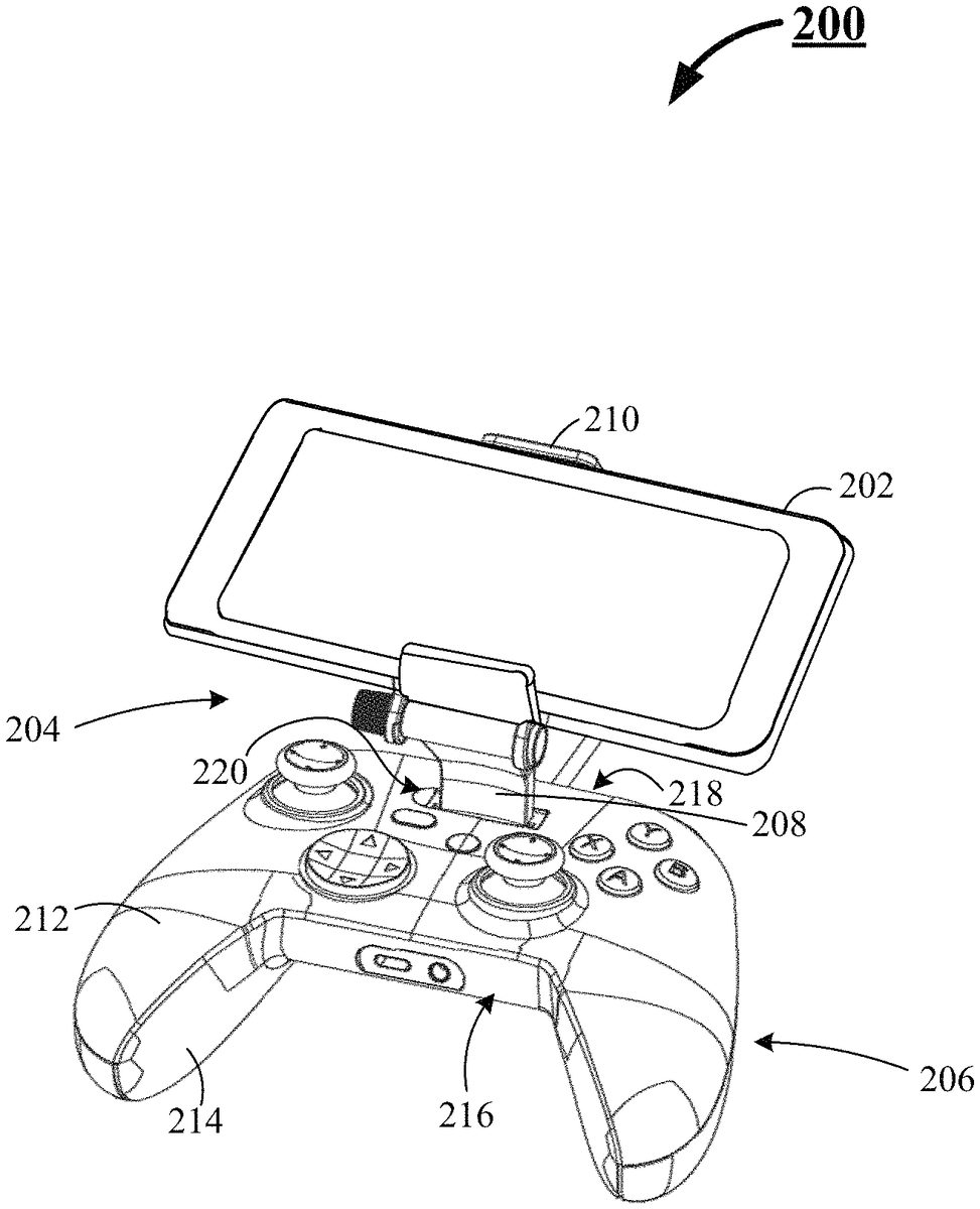
FIG.2shows a perspective view of a second embodiment of the video gaming system200. The video gaming system200preferably includes at least a computing device202supported by a stand204above a video game controller206. In a preferred embodiment the stand204includes a support portion208linked to a cradle portion210. The cradle portion210confines and secures the computing device202during a user's operation of the video gaming system200.
The video game controller206is in electronic communication with said computing device202, and includes at least, but is not limited to, a cover portion212and a base portion214. The cover portion212when secured to the base portion214forms a video game controller housing216(also referred to herein as controller housing216). The cover portion212provides a front edge218, and an aperture220offset from the front edge218.
FIG.3shows the support portion208Of the stand204further preferably provides a boss222and a pocket224. In this preferred embodiment, as shown byFIG.5, the aperture220is configured to confine and promote passage of the support portion208through the cover portion212. And as shown byFIG.5, the base portion214provides a retention pocket226and a retention boss228. Boss222(ofFIG.3) interacts with retention pocket226, the interaction between boss222and retention pocket226constrains the support portion208, within the aperture220. The interaction of pocket224and retention boss228, mitigates an inadvertent removal of the support portion208from aperture220. It is noted that in this second embodiment of the video gaming system200, the stand204is removably secured to the video game controller housing216absent the use of hardware, that is the stand204is manually pushed into the aperture220to install the stand204to the video game controller housing216, and manually pulled out of the aperture220to uninstall the stand204from the video game controller housing216.
FIG.4further shows a top perspective view of the video gaming system200, in which the cover portion212, provides a plurality of input button apertures230which facilitates an interaction by the user with a plurality of input buttons232and a joystick234. Each input button232is confined by its corresponding input button aperture230, and the joystick234is confined by its corresponding input button aperture230.
As shown byFIG.7, when the computing device202is confined by the cradle portion210, and the stand204is secured by the controller housing216, the computer device202overhangs at least a portion of the cover portion212and visually obscures a number of the plurality of input buttons232and the joystick234, when the user is viewing the (mobile) video gaming system200from a top plan view vantage point as shown byFIG.8.
FIG.8further shows the computing device202has a length240, greater than its width242, and a display screen245secured to a back246, and in which the stand204(ofFIG.7) is manually removably secured to the controller housing216upon full engagement of the support portion within the aperture220(ofFIG.4).
Returning toFIG.7, the support portion208provides a hinge member248, which corresponds to, and is in contact adjacency with, a hinge member250of the cradle portion210. The corresponding hinge members (248&250) are linked one to the other by way if a hinge pin252(ofFIG.4). The hinge pin252promotes an articulation of the cradle portion210relative to the support portion208. The hinge pin252interacts with provided mechanical hardware254(ofFIG.4) such that when a desired angle between said support portion208and said cradle portion210is selected, the mechanical hardware254is engaged to maintain said desired angle between the support portion208and the cradle portion210. As further shown byFIG.8, the controller housing216provides both right-side and left-side input module portions (255&256respectively). Each of the input module portions (255&256) hosts, as shown byFIG.7, a plurality of input mechanisms including, but not limited to, buttons232, joysticks234, and triggers258.
Returning toFIG.4, shown therein is an audio signal input/output port260arranged at a transversal portion262of said controller housing216, said audio signal input/output port260is separate and distinct from a combined power input and audio signal input/output port264(ofFIG.6) positioned on said front edge218(ofFIG.6). Additionally,FIG.6shows a printed circuit board assembly266. The printed circuit board assembly266is housed within the video game controller housing216. In this preferred embodiment, the printed circuit board assembly266(ofFIG.8) provides a gaming processor268(ofFIG.8). The gaming processor268is in electrical communication with: management and power pass through PMPP100(ofFIG.1), said power management and power pass through PMPP100communicating with said power input port270.
FIG.9shows a front view in elevation of a third embodiment of a video gaming system300. The video gaming system300, includes at least, but not limited to, a computing device302. The computing device302provides at least a combined audio and data input/output port304, as well as a processor306, and a transceiver device308. The processor306in electrical communication with each the combined audio and data input/output port304, and the transceiver device308. The computing device302further provides a display screen318, and a back cover320(ofFIG.11). The back cover320, encloses the processor306and is secured to the display screen318. The securement of back cover320to the display screen318forms an enclosed edge322(ofFIG.11) around a perimeter324(ofFIG.10) of the computing device302. The perimeter324includes at least two opposing sides326&328, respectfully, ofFIG.10.
FIG.10additionally shows that the video gaming system300, preferably further includes a bridgeless video game controller330in electronic communication with the processor306(ofFIG.9). In this preferred embodiment, the bridgeless video game controller330provides a pair of video game control modules332&334(ofFIG.9) respectfully. Each video game control module332or334is secured to a side of the two opposing sides326&328, and each video game control module (332or334) is supported by the computing device302, rather than the pair of video game control modules332&334supporting the computing device302.
The (mobile) video gaming system300, which preferably includes the bridgeless (electronic) video game controller330supported by the computing device302further includes and interacts with an audio headset336(ofFIGS.16&17). The bridgeless (electronic) video game controller330is in direct, wired electronic communication with the processor306by way of the combination audio and data input/output port304of said computing device302, and a combination audio and data input/output port305of the bridgeless (electronic) video game controller330.
As shown byFIG.11, the pair of video game control modules332&334of the bridgeless (electronic) video game controller330preferably includes at least a right-side input module portion338, a left-side input module portion340, and a tension free combination power and data communication cable342(also referred to herein as tension free cable342). The tension free cable342is disposed between the right-side and left-side input module portions338&340. The tension free cable342facilitates both data and power transfer between the right-side and left-side input module portions338&340. The tension free cable342provides no structural support for neither said right-side nor said left-side input module portions338&340.
As shown byFIG.10, the video game controller330, utilizes a pair of clamp assemblies, i.e., a right-side clamp assembly344and a left-side clamp assembly346. The right-side clamp assembly344is secured to and independently interacts with the right-side input module portion338while the left-side clamp assembly346is secured to and independently interacts with the left-side input module portion340. The right side and left side clamp assemblies344&346, in unison, cooperatively attach and secure the bridgeless (electronic) video game controller330to the computing device302, wherein the computing device302provides all structural support for each the right-side input module portion338and said left-side input module portion340by way of the corresponding right-side clamp assembly344and left-side clamp assembly346.
As further shown byFIG.11, each right-side input module portion338and left-side input module portion340include at least, but are not limited to, a top enclosure (348&352) and a corresponding bottom enclosure (350&354), each top enclosure and a corresponding bottom enclosure join to form corresponding input module housing (356&358). As further shown byFIG.10, the (mobile) video gaming system300, wherein the right-side and left-side input module portions338&340provide a plurality of input devices including, but not limited to, buttons360, joysticks362, and triggers364.
FIG.12shows the right-side clamp assembly344, whileFIG.15shows the left-side clamp assembly346, each of which are formed from a common set of components. The common set of components include, but are not limited to, a force translation shaft366secured to the right-side input module portion338(ofFIG.10), else the left side input module portion340OfFIG.10), by a retention clip368as shown inFIG.10. The retention clip368provides a mounting portion370and a securement portion372as shown byFIG.14. The mounting portion370is secured to the input module housing (356or358), while securement portion372interacts with a retention grove374, which is provided by the force translation shaft366. The securement portion372precludes a vertical translation of the force translation shaft366, relative to its corresponding input module portion (338or340), while promoting rotation of the force translation shaft366relative to its corresponding input module portion (338or340).
FIG.15reveals an actuation knob376communicating with a multi sided head portion378of the force translation shaft366, and a pair of jaws (380&382) communicating with the force translation shaft366. The pair of jaws (380&382) are responsive to a rotational input force applied to the actuation knob376. The pair of jaws (380&382) facilitate attachment of each the right-side input module portion338, and the left-side input module portion340to the computing device302. A top plan view of an embodiment of the multi sided head portion378is shown byFIG.13.
FIG.15further reveals that the force translation shaft366presents a left-hand383thread on a proximal end and a corresponding right-hand thread385on an opposing distal end, such that when a clockwise rotation is applied to said force translation shaft366, said pair of jaws (380&382) advance toward one another thereby closing said pair of jaws (380&382) onto said computing device302, further when a counter-clockwise rotation is applied to said force translation shaft366, said pair of jaws (380&382) retract from one another thereby opening said pair of jaws (380&382) from said computing device302permitting removal of said corresponding video game control modules (344&346ofFIG.112) from said computing device302.
FIGS.16&17show an audio headset336includes at least, but not limited to, a right-hand speaker384and a left-hand speaker386, each right-hand and left-hand speakers (384&386) are housed within a corresponding right-hand and left-hand speaker housing (388&390). In a preferred embodiment, a head band392is disposed between and secured to each the right-hand and left-hand speaker housings (388&390).
FIG.17reveals a power and audio input communication port394provided by the right-hand speaker housing388, else provided by the left-hand speaker housing390. An audio input/output cable396, shown inFIG.16, the audio input/output cable396provides a first connector398and a second connector400, the second connector400distil from the first connector398, the first connector398interacts with an input/output communication port402ofFIG.17, else the second connector400interacts with the input/output communication port402.
FIG.17further reveals a combination power and audio input port404provided by the right-hand speaker housing388, else provided by the left-hand speaker housing390; an energy storage device406housed by the right-hand speaker housing388else housed by the left-hand speaker housing390, the energy storage device406interacts with the combination power and audio input port404and a charging cable408configured for connection to the combination power and audio input port404when the energy storage device406is charging.
Returning toFIG.16, shown therein is a microphone409configured for connection to: the power and audio input communication port394(ofFIG.17); an audio processor410; and a transceiver device412. The audio processor410and the transceiver device412are configured to cooperate with the corresponding processor306(ofFIG.9) and the transceiver device308(ofFIG.9) of the computing device302(ofFIG.9).
FIG.18shows a mobile video gaming system500that includes at least, but not limited to, a computing device502. The computing device502presents a fixed length504greater than its width506, said computing device502provides a first combination data/power connector508. A first video game control module510provides a second combination data/power connector512. The second combination data/power connector512is in electronic communication with the first combination data/power connector508, thereby facilitating passage of data and power and audio signals between said first video game control module510and the computing device502. The mobile video gaming system500preferably further includes a second video game control module514in electronic communication with the first video game control module510, and a non-elastic, fixed length, flexible strap (“Strap”)516(ofFIG.19) disposed between and secured directly to each the first video game control module510and the second video game control module514. In a preferred embodiment, the Strap516includes two layers of webbing with a power and data conductor517, sandwiched between the two layers of webbing.
FIG.19further shows that upon securement of the strap516to each the first video game control module510and the second video game control module514, neither the strap516, nor the first video game control module510, nor the second video game control module514facilitate any adjustment to accommodate a length of a computing device different than the fixed length504of the computing device502.
Continuing withFIG.19, in which the first video game control module510further provides a power input port518and an audio signal port520. The power input port518facilitates transfer of power from an external charger to a battery522(ofFIG.18) of the computing device502(ofFIG.18), and the audio signal port520facilitates transfer of audio signals between an audio processor524(ofFIG.18) (such as Cmedia's CM6206 audio codec chip) of the computing device502and an external audio device (such as the audio headset336ofFIG.16).
As shown byFIG.20, the second video game control module514provides a hinged hatch526and a latch528, the hinged hatch526interacts with the latch528. The interaction of the hinged hatch526with the latch528confines and restrains the computing device502(ofFIG.18) within the first video game control module510and said second video game control module514. In a preferred embodiment, the latch528includes at least, but is not limited to, two components: a ball560, which is secured to the hinged hatch526and a receiver562, which is secured to a strap restaurant member564of the second video game control module514.FIG.21shows a front view in elevation of the ball560, whileFIG.22shows a top plan view of the receiver562.FIG.23shows a front plan view of an (alternate) video game controller600, which supports a smart device holder602. The smart device holder602is shown in its retracted position, whileFIG.24shows the smart device holder602is shown in its expanded form. In a preferred embodiment of the video game controller600, a pair of video game controller input modules604and606are joined one to the other by way of a rigid, non-expandible bridge section608.
As shown byFIG.25, the video game controller600supports the smart device holder602, which in turn secures a smart device610in noncontact adjacency relative to a pair of video game controller input modules,604and606. The term smart device refers to all classes of Wi-Fi enabled computers, Wi-Fi enabled cell phones, and Wi-Fi enabled television sets, wherein said Wi-Fi enabled computers, Wi-Fi enabled cell phones, and Wi-Fi enabled television sets each have imbedded operating systems.
FIG.26shows a bottom view in elevation of the video game controller600supporting the smart device holder602. The smart device holder602secures and confines the smart device610in a fixed position, elevated above and lying in a plane612(as shown in dashed line form) parallel to a plane614(as shown in dashed line form). The plane614bifurcates the pair of video game controller input modules604and606and the rigid, non-expandible bridge section608. The rigid, non-expandible bridge section joins together the pair of video game controller input modules604and606.FIG.26further shows the smart device holder602includes a cradle portion616non-movably affixed perpendicular to a stand portion618, wherein the stand portion is joined to the video game controller600such that the stand portion618is perpendicular to each of the planes612and614, and the cradle portion616is affixed perpendicular to the stand portion618.
FIG.27shows a bottom view in elevation of an (alternative) video game controller700(also referred to herein as a video gaming system700). The video game controller700includes an expandible, spring free, rigid bridge section702, and a pair of video game input modules,704and706non-removably secured (i.e., non-removably coupled) to the expandible, spring free, rigid bridge section702. Non-removably secured (or non-removably pinned, non-removably fastened, etc.) can include, for example, being unable to be removed without the use of tools, fixedly secured, integral, etc. Likewise, the term spring free describes attributes of, for example, the rigid bridge section702operating without the use of a spring to provide the expandability to the rigid spring section702.FIG.27further shows that at least one of the video game input modules704and706, provides a power passthrough port705and an audio jack input port707. The power passthrough port705conducts current from an external source to a smart device, such as smart device610ofFIG.26, when the smart device610is electrically connected to the power passthrough port705. The audio jack input port707conducts audio signals to an audio headset, such as audio headset336ofFIG.16, when the audio headset336is plugged into the audio jack input port707.
FIG.28shows a front plan view of the video game controller700ofFIG.27, which reveals that the spring free rigid bridge section702is a collapsible, X frame, spring free, rigid bridge section702(also referred to herein as bridge section702). Preferably, as shown byFIG.30, the bridge section702, is formed from a plurality of top struts708and bottom struts710. The top struts708and the bottom struts710are pinned, by way of a respective connection pin714to: each of a king post712of the bridge section702on a proximal end; and to a respective one of the pair of video game controller input modules604and606on a distal end.FIG.28further shows that each of the video game controller input modules704and706(also referred to herein as input modules704and706) provide a plurality of input devices including, but not limited to, buttons601, joysticks603, triggers605, and a D pad607.
FIG.29reveals the smart device holder602includes a spring member716enclosing a spring guide shaft717. Spring member716is used to maintain the smart device holder602in its retracted form. The spring member716further allowing the smart device holder602to extend to its expanded form upon an application of a lateral force. The smart device holder602, as shown byFIG.29, is in its extended form. In a preferred embodiment of the (alternative) video game controller700, the smart device holder602, is manually attached to the king post712ofFIG.28, absent the need for or use of tools. The stand portion618(ofFIG.26) of the smart device holder602(ofFIG.26) inserts vertically into a securement aperture718(each ofFIG.30) of the king post712.FIG.30more clearly shows the top struts708and bottom struts710are pinned, by way of a connection pin714, to each a king post712on a proximal end, and to each of the pair of video game controller input modules604and606on a distal end.FIG.30further includes a front surface713surrounding the securement aperture718.
FIG.31shows a bottom view in elevation of the video game controller700ofFIG.30in which the smart device holder602is manually attached to the king post712, the attachment made absence the use of tools.FIG.31further shows the collapsible, X frame, spring free, rigid bridge702is formed from the plurality of top struts708and bottom struts710pinned to the input modules604and606as well as to the king post712. The top struts708and bottom struts710are linked one to the other by way of a mechanical joint720. In a preferred embodiment the mechanical joint720is a referred to as a ball and socket joint720.
FIG.32shows a bottom view in elevation of a preferred embodiment in which a first member722of the ball and socket joint720ofFIG.31is a ball portion of the ball and socket joint720.
FIG.33shows a bottom view in elevation of a preferred embodiment in which a second member724of the ball and socket joint720ofFIG.31is a socket portion of the ball and socket joint720.
FIG.34shows a cross sectional view of struts708,710ofFIG.31.
FIG.35a side view in elevation of a smart device726, which may take the form of a smart phone, mini tablet, tablet, or other wireless communication enabled device which provides a viewing screen. For purposes of illustration, the smart device726is shown ad a mini tablet, which has at least a length greater than a length of the smart device610ofFIG.31.
FIG.36shows a front plan view of video game controller700ofFIG.30in its collapsed form, with the pair of video game controller input modules604and606secured thereon.
FIG.37shows a bottom view in elevation of the video game controller700in its collapsed form, the smart device holder602manually attached to the collapsible, X frame, spring free, rigid bridge702, and the smart device610secured to the collapsible, X frame, spring free, rigid bridge702by way of the smart device holder602. In this configuration, as shown byFIG.37, the smart device610obscures the plurality of input devices ofFIG.28including, but not limited to, buttons601, joysticks603, triggers605, and a D pad607of the pair of video game controller input modules604and606. The obscurement of the input devices is further shown byFIG.63.
FIG.38shows a side view in elevation of the top strut708of the plurality of struts in its extended form. The top strut708provides a rod portion728and a cylinder portion730. The rod portion728provides an attachment aperture731and a breather orifice732. The cylinder portion730provides a seal portion734(shown in partial cutaway byFIG.39), and the first member722of the mechanical joint720(ofFIG.31) and a second attachment aperture736. In a preferred embodiment, the rod portion728is in slidable, frictional contact adjacency with the seal portion734of the cylinder portion730of the strut708. The seal portion734is formed on an internal surfaces of the cylinder portion730.
FIG.39shows the top strut708ofFIG.38in its contracted form.
FIG.40shows the bottom strut710of the plurality of the plurality of bottom struts710in its extended form. The bottom strut710provides the rod portion728and a cylinder portion738. The rod portion728provides the attachment aperture731and the breather orifice732. The cylinder portion738provides a seal portion734, the second member724of the mechanical joint720(ofFIG.31) and the second attachment aperture736.
FIG.41shows the bottom strut710strut ofFIG.40in its contracted form. In an embodiment ofFIG.40the rod portion728resides internal to the cylinder portion738and is in slidable, frictional contact adjacency with the seal portion734of the cylinder portion738of the bottom strut710. In a preferred embodiment the seal portion734if formed from a plurality of O-rings740.
FIG.42shows a bottom plan view of a video game controller750. The video game controller750is structurally, mechanically comparable to the video game controller600, with the addition of a pair of touch sensitive screens802, secured to a back side of their respective input modules604and606. As with video game controller600, the input modules604and606are non-removably secured to the rigid, non-expandible bridge section608, and the smart device holder602secures and maintains the smart device610in a fixed position, elevated above and lying in a plane, elevated above, offset from, and parallel to the top surface621, of the rigid, non-expandible bridge section,608. The pair of touch sensitive screens802are in electrical communication with and mechanically secured to their respective video game controller input modules604and606. The output signal of each touch sensitive responds in a plurality of ways, depending on a direction of a swipe (up or down vertically, of back or forth horizontally). Additionally, tapping on a top portion, or a bottom portion of the screen generates on alternate single type than at obtained by a directionally centric swipe.
FIG.43shows a bottom plan view of the collapsible, X frame, spring free, rigid bridge, video game controller800(also referred to herein as a video gaming system800), in its expanded form and providing the pair of touch sensitive screens802on each of the pair of video game controller input modules604and606. The pair of touch sensitive screens802are in electrical communication with and mechanically secured to their respective video game controller input modules604and606.
FIG.44shows a front plan view if a collapsible, X frame, spring free, video game controller chassis900(also referred to herein as chassis900). Chassis900is depicted in its expanded form and includes the plurality of top struts708and bottom struts710pinned, by way of a connection pin714, to each the king post712on a proximal end and to each of a pair of module support struts902on the distal end.
FIG.45shows a front view in elevation of an input module attachment rail904, which presents at least one mounting aperture903(three shown). The mounting aperture(s)903promotes attachment of the input module attachment rail904to the module support strut902.
FIG.46shows a side view in elevation of the input module attachment rail904ofFIG.45. The input module attachment rail904provides a video game controller input module retention notch910.
FIG.47shows a cross-section view in elevation of the input module attachment rail904ofFIG.45.
FIG.48shows a front plan view if the chassis900in its expanded form with a pair of input module attachment rails904ofFIG.46secured to the module support struts902.
FIG.49shows a front plan view if the chassis900ofFIG.48in its expanded form with a pair of manually attachable and detachable video game input modules906and908, slidingly attached to each of their corresponding input module attachment rails904ofFIG.46. In a preferred embodiment the pair of manually attachable and detachable video game input modules906and908are wireless manually attachable and detachable video game input modules906and908
FIG.50shows a front plan view of the chassis900with attached input module attachment rails904ofFIG.48. The chassis900is shown in its contracted form.
FIG.51shows a top plan view of the chassis900with input module attachment rails904secured thereon.FIG.50further shows that each input module attachment rail904provides a pair of module restraints905. The module restraints905secure the pair of manually attachable and detachable video game input modules906and908adjacent the pair of module support struts902of the chassis900as shown byFIG.60.
FIG.52shows a bottom plan view of the chassis900in its collapsed form with the input module attachment rails904attached thereon.FIG.52further depicts the smart device holder602that includes the cradle portion616. The smart device holder602is non-removably secured to a stand portion618. The stand portion618is joined to the king post712of the chassis900such that the stand portion618is perpendicular to each of the king post712and the cradle portion. The smart device holder602is manually attached to the king post712portion of the chassis900absence the use of tools.
FIG.53shows a back view in elevation of the chassis900with input module attachment rails904secured thereon.FIG.53further shows that each bottom strut710is secured to its respective module support struts902of the chassis900by way of way of corresponding connection pins714.
FIG.54shows a left side view in elevation of the smart device holder602ofFIG.52in its retracted form.
FIG.55shows the left side view in elevation of the smart device holder602ofFIG.54in its expanded form. In a preferred embodiment the spring member716enclosing the spring guide shaft717and applies a tension force between a fixed smart device stop615and a movable smart device stop617. The spring member716maintains the smart device holder602in its retracted form. The spring member716further allowing the smart device holder602to extend to its expanded form and hold a smart device such as the smart device726ofFIG.35under a compressive load.
FIG.56shows a bottom plan view of chassis900in its collapsed form with the input module attachment rails904ofFIG.50, attached thereon.FIG.56further shows the stand portion618of the smart device holder602attached to the king post712. The smart device holder602is tool free manually attached to the king post712of the chassis900. A partial cutaway of the king post712shows the stand portion618of the smart device holder602provides a retention barb912, and the king post712of the chassis900provides a retention aperture914. An interaction of the retention barb912protruding through the retention aperture914to maintain the smart device holder602removably secured to the chassis900.
FIG.57shows a side view in elevation of the smart device610.
FIG.58shows a bottom view in elevation of a left-side video game input module906.
FIG.59shows a bottom view in elevation of a right-side video game input module908.
FIG.60shows a bottom view in elevation of each the left-side and right-side video game input modules906and908are slidingly secured to the input module attachment rails904of the chassis900. The smart device holder602, is manually removably secured to the controller chassis900. The smart device holder602secures and maintains the smart device610in a fixed position, elevated above and lying in a plane612(as shown in dashed line form) parallel to a plane614(as shown in dashed line form). The plane614bifurcates the pair of video game (controller) input modules906and908, and the king post712.FIG.60further shows a wireless charger connection port916. The wireless charger connection port916conducts current from an external source to a wireless charger918shown byFIGS.61and62.
FIG.61shows a side view in elevation of the smart device holder602with a wireless charger918secured thereon. In a preferred embodiment, the wireless charger918, such as the “MagSafe” wireless charger by Apple Inc., is secured to the movable smart device stop617.
FIG.62shows a top view of the smart device holder6t02with a wireless charger918secured thereon.
FIG.63shows a front plan view with the (alternative) video game controller700in its collapsed position, the smart device610secured to the video game controller700by smart device holder602. In a preferred embodiment, the smart device610obscures the plurality of input devices including, but not limited to, buttons601, joysticks603, triggers605, and a D pad607of the pair of video game controller input modules604and606each ofFIG.28.FIG.63further shows that a signal cable611transmits input signals from the video game controller700to the smart device610. The signal cable611includes a first connector613secured to the fixed smart device stop615of the smart device holder602, and a second connector619plugged into the smart device610.
Video game controller600includes a pair of video game control modules, such as604and606, non-removably secured to a rigid, non-expandible bridge section, such as608. Then a stand portion, such as618, of a smart device holder, such as602, is manually pushed through a securement aperture, such as609, of a rigid, non-expandible bridge section, such as608. A retention barb, such as912, of a stand portion, such as618, of a smart device holder, such as602, precludes an inadvertent removal of a smart device holder, such as602, from a rigid, non-expandible bridge section, such as608. When seating of a smart device stand, such as602, into a rigid, non-expandible bridge section, such as608is complete, a smart device, such as610, is affixed to a cradle portion, such as616, of a smart device holder such as602, and connected electrically to a video game controller, such as video game controller600, by way of a signal cable, such as611. When a smart device, such as610, is affixed to a smart device holder, such as602, a smart device, such as610, lies in a plane, such as612, elevated above, offset from, and parallel to a top surface, such as621, of a rigid, non-expandible bridge section, such as608.
A video game controller, such as video game controller700, includes a pair of video game control modules, such as704and706, pined to an expandible, spring free, rigid bridge section, such as702, by a plurality of securement pins, such as714. In a preferred embodiment a stand portion, such as618, of the smart device holder, such as612, is vertically inserted through a securement aperture, such as718, of a king post, such as king post712, of an expandible, spring free, rigid bridge section, such as702and secured within a king post, such as king post712. Then, a smart device, such as610, is affixed to a cradle portion, such as616, of a smart device holder such as602, and connected electrically to a video game controller, such as video game controller600, by way of a signal cable, such as611. When a smart device, such as610, is affixed to a smart device holder, such as602, a smart device, such as610, lies in a plane, such as612, elevated above, offset from, and parallel to a front surface, such as713, of a king post, such as king post712.
A collapsible, X frame, spring free, video game controller, chassis, such as900, includes a plurality of top struts, such as top strut708, and a plurality of bottom struts, such as bottom strut710. A proximal end of each top strut and each bottom strut are preferably pinned to a king portion, such as king post712, of an X frame, spring free, video game controller, chassis, such as900by a connection pin, such as714. The term spring free above describes attributes of, for example, chassis900operating without the use of a spring to provide the collapsibility to the chassis900. While a distal end of each top strut and each bottom strut are preferably pinned, by way of a connection pin, such as714, to a pair of module support struts, such as module support struts902, of an X frame, spring free, video game controller, chassis, such as900. Next an input module attachment rail, such as input module attachment rail904, is secured to each respective module support struts, such as module support struts902, and a pair of wireless video game input modules, such as video game input modules906and908, are manually removably secured to their respective module attachment rail, such as input module attachment rail904.
FIG.64shows a block diagram power management and power pass through circuit100(“PMPP”), which includes a operating system detection circuit920of an embodiment of a video gaming system922. Said video gaming system922, includes at least, but is not limited to, a processor924, which provides at least a computing portion926and a memory portion928. The video gaming system922further includes an energy storage device104within a computing device102, while a video game controller930provides a second energy storage device108. Said processor924communicates with a video game controller930, said video game controller930provides at least, but is not limited to, a second energy storage device108. Said PMPP100precludes a simultaneous bidirectional current flow between said computing device102and said video game controller930.
In a preferred embodiment, the communication between the computing device102and the video game controller930is achieved via a wired connection circuit112, however as one skilled in the art understands, communication between the computing device102and the video game controller930may be achieved wirelessly. The wired connection circuit112preferably includes a power and signal cable114(also referred to herein as cable114). Cable114preferably provides a connector116, which is specifically configured to interface with an interface connector118, said interface connector118provides a predetermined number of contacts including, but not limited to, a power contact and a ground contact.
In a preferred embodiment, stored the memory portion928of the processor924is a plurality of video game centric operating systems (also known as multiple sets of firmware) for use in operating the video game controller930, and controlling the interface between a plurality of input devices such as buttons232and a joystick234(FIG.4) and computing device102Each set of firmware of the multiple sets of firmware is specific to an operating system of the computing device102(also referred to herein as a smart device102).
Examples of firmware sets include: iOS compatible firmware compatible with Apple's iOS operating system (iOS is a proprietary mobile operating system that runs on mobile devices such as the iPhone, iPad, iPod Touch); Android compatible firmware compatible with Google's Android Operating System, which is software developed by Google; and then customized for various smart devices; or Mobil Linux compatible firmware compatible with Mobil Linux operating system (Mobil Linux is an operating system for smart devices and is an open source Operating System).
In an operation of an embodiment of a video gaming system, such as video gaming system922, multiple different sets of firmware are preloaded into the memory portion928of the processor924. Upon connection to a computing device, such as computing device102, by a connection circuit, such as connection circuit112, a operating system detection circuit, such as operating system detection circuit920, determines the operating system being utilized by the connected computing device, such as computing device102. In a preferred embodiment, the operating system detection circuit920analysis interface connector118, which provides a predetermined number of contacts including, but not limited to, a power contact and a ground contact. Based on the physical location of those contacts presented by interface connector, the operating system detection circuit920, directs the computing portion926of the processor924as to which video game controller operating system stored in the memory portion928of the processor is to be used to effectuate communication with the computing device102.
FIG.65is a block diagram of the operating system detection circuit920. Included by the operating system detection circuit920is a printed circuit board932/266shown as s separate printed circuit board, which mechanically communicates with printed circuit board assembly266(ofFIG.6). However, in a preferred embodiment an operating system detection integrated circuit938is mounted on a printed circuit board assembly932/266. The operating system detection integrated circuit938is in electrical communication with the processor924. The printed circuit board assembly932/266is housed within a cloud gaming controller housing1018(ofFIG.66). The operating system detection integrated circuit938is further in both mechanical and in electrical communication with the interface connector118of the as connection circuit112, as shown byFIG.63, which mechanically and electrically communicate the computing device102.
The wired connection circuit112, communicates power and signals between the computing device102and the video game controller106. The wired connection circuit112preferably includes a power and signal cable114(also referred to herein as cable114). Cable114preferably provides a first interface connector116on a first end, which is specifically configured to interface with the computing device102, and a second interface connector118, which is specifically configured to interface with the video game controller106. Interface connector118, provides a predetermined number of contacts including, but not limited to, a power contact, a ground contact, and at least a signal contact.
FIG.66shows a perspective view of an embodiment of a cloud gaming controller1012of a video gaming system1002configured for use with a smart device, such as a Wi-Fi enabled television set1022(also referred to herein as Wi-Fi TV722) (ofFIG.67). The Wi-Fi TV1022preferably includes at least a support stand1024and provides a video game controller communication port1026.
The cloud gaming controller1012is in electronic communication with said Wi-Fi TV1022, and includes at least, but is not limited to, a cover portion1014and a base portion1016. The cover portion1014when secured to the base portion1016forms a cloud gaming controller housing1018(also referred to herein as controller housing1018). The cover portion further provides an aperture1020offset from a front edge1030of the cover portion1014.
In a preferred embodiment, communication between the Wi-Fi TV1022and the cloud gaming controller1012is achieved via a wired connection circuit1004, however as one skilled in the art understands, communication between the Wi-Fi TV1022and the cloud gaming controller1012may be achieved wirelessly. The wired connection circuit1004preferably includes a power and signal cable1006(also referred to herein as cable1006). Cable1006preferably provides a connector1008, which is specifically configured to interface with a cloud gaming communication port1026(ofFIG.67) as well as an interface connector1010. Said interface connector1010provides a predetermined number of contacts including, but not limited to, a power contact and a ground contact. The interface connector1010is specifically configured to interface with a mating connector940(ofFIG.65). Said mating connector940is mounted on the printed circuit board932/266(ofFIG.65), and mechanically and electronically communicate with the operating system detection integrated circuit938(ofFIG.65)
Further shown byFIG.66is a cloud gaming activation button1028adjacent aperture1020. An activation of the cloud gaming activation button1028signals the Wi-Fi TV1022to establish a communication link with the cloud to gain access to a plethora of video game stored in the cloud and compatible with the cloud gaming controller1012.
FIG.68shows a bottom plan view of a cloud gaming controller1102of a cloud gaming system1100. Said cloud gaming controller1102is in electronic communication with said Wi-Fi TV1022(ofFIG.67), and includes at least, but is not limited to, a cover portion1104and a base portion1106. The cover portion1104when secured to the base portion1106forms a video game controller housing1108(also referred to herein as controller housing1108). The communication between the Wi-Fi TV1022and the cloud gaming controller1102is achieved via a wired connection circuit1110, however as one skilled in the art understands, communication between the Wi-Fi TV1022and the cloud gaming controller1012may be achieved wirelessly. The wired connection circuit1110preferably includes a power and signal cable1112(also referred to herein as cable1112). Cable1112preferably provides a connector1114, which is specifically configured to interface with a cloud gaming communication port1026(ofFIG.67) as well as an interface connector1010. Said interface connector1010provides a predetermined number of contacts including, but not limited to, a power contact and a ground contact. The interface connector1010is specifically configured to interface with a mating connector940(ofFIG.65). Said mating connector940is mounted on the printed circuit board932/266(ofFIG.65), and mechanically and electronically communicate with the operating system detection integrated circuit938(ofFIG.65)
FIG.69is a block diagram of a video game controller1116in electronic communication with a smart device (e.g., smart device102). Said video game controller1116includes a processor1118with embedded operating system detection firmware1120. Said processor1118further includes a computer portion1122and a memory portion, said memory portion stores multiple firmware sets. When said video game controller1116is connected to the smart device, said embedded operating system detection firmware1120detects which operating system, of a plurality of smart device operating systems, operates said smart device. Said embedded operating system detection firmware1120further selects, from said multiple firmware sets stored in said memory1124of said processor1118, a firmware set compatible with said detected operating system of said smart device. Said embedded operating system detection firmware1120still further directs loading of said selected firmware set onto said computing portion1122of said processor1118. Said selected firmware set actively interacts with said detected operating system of said smart device during game play of a video game, said video game displayed on a viewing screen of said smart device.
It is to be understood that even though numerous characteristics and configurations of various embodiments of the present invention have been set forth in the foregoing description, together with details of the structure and function of various embodiments of the invention, this detailed description is illustrative only, and changes may be made in detail, especially in matters of structure and arrangements of parts within the principles of the present invention to the full extent indicated by the broad general meaning of the terms in which the appended claims are expressed. For example, the elements may vary depending on the particular computing device without departing from the spirit and scope of the present invention.
Claims
- A video gaming system comprising: a smart device;a stand, said stand includes a support portion linked to a cradle portion, said cradle portion confines said smart device, said support portion provides a boss and a pocket;a game controller, said game controller in electronic communication with said smart device, said game controller comprising: a cover portion and a base portion, said base portion secured to said cover portion, said cover portion provides an aperture offset from an edge of said cover portion, said base portion provides a retention boss and a retention pocket, said retention pocket aligned with said aperture, said retention pocket promotes passage through and confinement of said support portion of said stand, said boss interacts with said retention boss, said interaction between said boss and said retention boss mitigates an inadvertent removal of said support portion from said aperture, wherein said cover secured to said base forms a controller housing, wherein said stand is removably secured to said controller housing absent use of hardware and further in which said game controller further comprising an operating system detection circuit, said operating system detection circuit in electronic communication with said smart device;and a wired connection circuit, comprising: a first interface connector in electronic communication with said smart device;a second interface connector in electronic communication with said game controller;and a power and signal cable disposed between said first and second interface connectors: and said operating system detection circuit provides an operating system detection integrated circuit (detection IC″), said detection IC is in electronic communication with said second interface connector, and in further electronic communication with a processor provided by said game controller, said processor providing a computing portion and a memory portion, said memory portion stores multiple different sets of firmware, wherein upon when said game controller is connected to said smart device, said detection IC detects which operating system, of a plurality of smart device operating systems, is operating on the smart device as a detected operating system of said smart device, said detection IC further directs said computing portion to load a selected firmware set, said selected firmware set is selected from said multiple different sets of firmware stored in said memory portion, wherein said selected firmware set is compatible with said detected operating system of said smart device.
- The video gaming system of claim 1, in which said cover portion provides a plurality of input button apertures which facilitates an interaction by a user with a joystick and a plurality of input buttons, wherein when said smart device is confined by said cradle portion, and said stand is secured by said controller housing, said smart device overhangs at least a portion of said cover and visually obscures a number of said plurality of input buttons and said joystick when said user is viewing said video gaming system from a top plan view vantage point.
- The video gaming system of claim 2, in which said smart device has a length greater than its width, a back portion and a display screen secured to said back portion, and in which said stand is manually removably secured to said controller housing upon full engagement of said support portion within said aperture;said support portion provides a first hinge member which corresponds to and is in contact adjacency with a second hinge member of said cradle portion, said first and second hinge members are linked one to the other by way of a hinge pin, said hinge pin promotes an articulation of said cradle portion relative to said support portion, said hinge pin interacts with provided mechanical hardware such that when a desired angle between said support portion and said cradle portion is selected, said mechanical hardware is engaged to maintain said desired angle between said support portion and said cradle portion.
- A video gaming system comprising: a smart device;a stand, said stand includes a support portion linked to a cradle portion, said cradle portion confines said smart device, said support portion provides a boss and a pocket;a game controller, said game controller in electronic communication with said smart device, said game controller comprising: a cover portion and a base portion, said base portion secured to said cover portion, said cover portion provides an aperture offset from an edge of said cover portion, said base portion provides a retention boss and a retention pocket, said retention pocket aligned with said aperture, said retention pocket promotes passage through and confinement of said support portion of said stand, said boss interacts with said retention boss, said interaction between said boss and said retention boss mitigates an inadvertent removal of said support portion from said aperture, wherein said cover secured to said base forms a controller housing, wherein said stand is removably secured to said controller housing absent use of hardware;and wherein said game controller includes at least a processor in electronic communication with said smart device, said processor provides a computing portion and a memory portion, said computing portion detects which specific operating system, of a plurality of available operating systems, said smart device is operating under as a detected specific operating system, said computing portion further selects, from multiple firmware sets stored in said memory portion, a firmware set compatible with said detected specific operating system of said smart device;and a wired connection circuit, comprising: a first interface connector in electronic communication with a video game controller communication port of said smart device, said video game controller communication port provides a plurality of contacts, said first interface connector provides a plurality of contacts (“IF contacts”), wherein each separate IF contacts of said interface connector is in electronic communication with its corresponding video game controller communication port contact;a second interface connector in electronic communication with said computing portion of said processor of said game controller;and a power and signal cable disposed between and in electronic communication with said first and second interface connectors, wherein said computing portion of said processor queries said plurality of contacts of said video game controller communication port, detects said specific operating system of said smart device, said computing portion further selects said firmware set compatible with said detected specific operating system of said smart device, said computer portion still further directs a loading of said selected firmware set onto said computer portion based on said queries.
- The video gaming system of claim 4, in which said cover portion provides a plurality of input button apertures which facilitates an interaction by a user with a plurality of input buttons, triggers, and a joystick confined by said input button apertures, and wherein when said smart device is confined by said cradle, and said stand is secured by said controller housing, said smart device overhangs at least a portion of said cover and visually obscures a number of said plurality of input buttons, triggers, and said joystick when said user is viewing said mobile video gaming system from a top plan view, vantage point.
- The video gaming system of claim 5, in which said smart device has a length greater than its width, and a display screen secured to a back of said smart device, and in which said stand is manually removably secured to said controller housing upon full engagement of said support portion within said aperture;said support portion provides a first hinge member which corresponds to and is in contact adjacency with a second hinge member of said cradle portion, said corresponding first and second hinge members are linked one to the other by way of a hinge pin, said hinge pin promotes an articulation of said cradle portion relative to said support portion, said hinge pin interacts with provided mechanical hardware such that when a desired angle between said support portion and said cradle portion is selected, said mechanical hardware is engaged to maintain said desired angle between said support portion and said cradle portion.
Disclaimer: Data collected from the USPTO and may be malformed, incomplete, and/or otherwise inaccurate.