U.S. Pat. No. 11,638,874
SYSTEMS AND METHODS FOR CHANGING A STATE OF A GAME OBJECT IN A VIDEO GAME
AssigneeSquare Enix Ltd.
Issue DateDecember 30, 2020
Illustrative Figure
Abstract
A computer-implemented method, gaming device and computer-readable medium for video game. The method includes maintaining a virtual space for a gaming environment. The method also includes repeatedly activating an event zone in the virtual space, wherein for one or more game objects having a position in the virtual space that is within the event zone when the event zone is activated, a state of the one or more game objects in the virtual space is changed. The method further includes displaying on a display device a visual representation of the event zone and a visual representation of a marker, the marker having a position in the virtual space. The method yet further includes changing the position of the marker such that a distance involving the marker and at least part of the event zone is related to a time remaining before the next repeated activation of the event zone.
Description
It is to be expressly understood that the description and drawings are only for purposes of illustrating certain embodiments and are an aid of understanding. They are not intended to and should not be limiting. DETAILED DESCRIPTION FIG.1is an illustration of a schematic block diagram of a computing device10in accordance with a non-limiting embodiment of the disclosure. In some embodiments, the computing device10is a dedicated gaming console similar to an Xbox™, Playstation™ or Nintendo™ gaming console. In other embodiments, the computing device10is a laptop computer. In yet other embodiments, the computing device is a mobile device such as a smartphone, a tablet. In yet other embodiments, the computing device10is a handheld gaming console. The computing device10may be any other computing device suitable for carrying out the embodiments of the disclosure. In the illustrated embodiment as shown inFIG.1, the computing device10comprises a non-transitory memory12(hereinafter “the memory12”), a processor11, an input/output module14, at least one power supply unit27, and may include any other suitable components typically found in a computing device used for playing video games. The various components of the computing device10may communicate with each other over one or more buses21, which can be data buses, control buses, power buses and the like. In some embodiments, the computing device10may include an internal game controller13(e.g. a touchscreen) or an external game controller17(e.g. a joystick) configured to receive input from a user (i.e. a player of the game), as well as an internal display device15(e.g. a touchscreen) or an external display device16(e.g. a computer monitor, a television set). The computing device10may be connected to a data network30via a network input/output interface25. Depending on the implementation, the data network30may be the internet, a local area network, a wireless network, a combination of such networks or still other forms of data networks. A user1may play ...
It is to be expressly understood that the description and drawings are only for purposes of illustrating certain embodiments and are an aid of understanding. They are not intended to and should not be limiting.
DETAILED DESCRIPTION
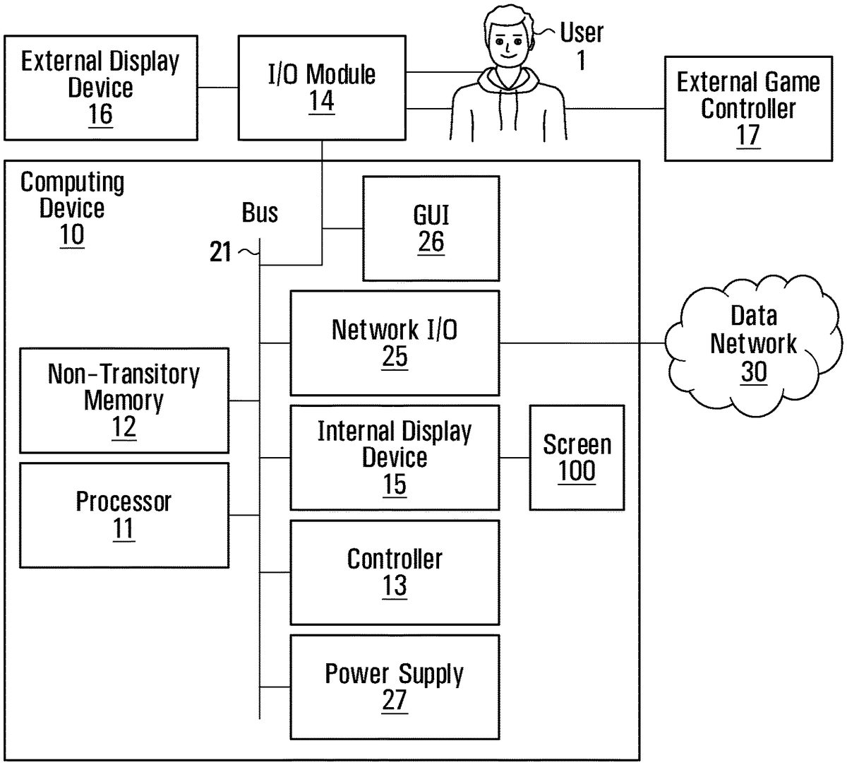
FIG.1is an illustration of a schematic block diagram of a computing device10in accordance with a non-limiting embodiment of the disclosure. In some embodiments, the computing device10is a dedicated gaming console similar to an Xbox™, Playstation™ or Nintendo™ gaming console. In other embodiments, the computing device10is a laptop computer. In yet other embodiments, the computing device is a mobile device such as a smartphone, a tablet. In yet other embodiments, the computing device10is a handheld gaming console. The computing device10may be any other computing device suitable for carrying out the embodiments of the disclosure.
In the illustrated embodiment as shown inFIG.1, the computing device10comprises a non-transitory memory12(hereinafter “the memory12”), a processor11, an input/output module14, at least one power supply unit27, and may include any other suitable components typically found in a computing device used for playing video games. The various components of the computing device10may communicate with each other over one or more buses21, which can be data buses, control buses, power buses and the like.
In some embodiments, the computing device10may include an internal game controller13(e.g. a touchscreen) or an external game controller17(e.g. a joystick) configured to receive input from a user (i.e. a player of the game), as well as an internal display device15(e.g. a touchscreen) or an external display device16(e.g. a computer monitor, a television set).
The computing device10may be connected to a data network30via a network input/output interface25. Depending on the implementation, the data network30may be the internet, a local area network, a wireless network, a combination of such networks or still other forms of data networks.
A user1may play a video game by viewing game images displayed on a screen100of the internal display device15or the external display device16and controlling aspects of the video game via the internal game controller13or the external game controller17. Accordingly, the computing device10receives inputs from the internal game controller13or the external game controller17via the input/output module14. The computing device10also supplies outputs to the internal display device15or the external display device16and/or an auditory device (e.g., a speaker, not shown) via the input/output module14. In other implementations, there may be more than one internal or external game controller and/or more than one internal or external display device connected to the input/output module14.
The processor11may include one or more central processing units (CPUs) having one or more cores. The processor11may also include at least one graphics processing unit (GPU) in communication with a video encoder/video codec (coder/decoder, not shown) for causing output data to be supplied to the input/output module14for display on the internal display device15or the external display device16. The processor11may also include at least one audio processing unit in communication with an audio encoder/audio codec (coder/decoder, not shown) for causing output data to be supplied to the input/output module14to the auditory device.
The memory12may include RAM (Random Access Memory), ROM (Read Only Memory), flash memory, hard disk drive(s), DVD/CD/Blu-ray™ drive and/or any other suitable memory device, technology or configuration. The memory12stores a variety of information including computer-readable instructions18, game data20and an operating system22.
When the computer device10is powered on, the processor11is configured to run a booting process which includes causing the processor11to communicate with the memory12. In particular, the booting process causes execution of the operating system22. The operating system22may be any commercial or proprietary operating system suitable for the computing device10. Execution of the operating system22causes the processor11to generate images displayed on the internal display device15or the external display device16, including various options that are selectable by the user1via the internal game controller13or the external game controller17, including the option for the user1to start and/or select a video game to be played. The video game selected/started by the user1is encoded by the computer-readable instructions18.
The processor11is configured to execute the computer-readable instructions18such that the processor11is able to perform various kinds of information processing functions related to the video game that it encodes. In particular, and with reference toFIG.2, execution of the computer-readable instructions18causes the processor to execute a game data processing function23and game rendering processing function24, which are now described.
The game rendering processing function24includes generation of a game image to be displayed on the internal display device15or the external display device16. For its part, the game data processing function23includes processing of information representing progress of the game or a current state of the game (e.g., processing of information relating to the game that is not necessarily displayed on the internal display device15or the external display device16). The game data processing function23and the game rendering processing function24are illustrated inFIG.2as forming part of a single set of computer-readable instructions18. However, in other embodiments, the game data processing function23and the game rendering processing function24may be separate programs or sets of computer-readable instructions stored in separate memories and executed by separate, possibly distant, processors. For example, the game data processing function23may be performed on a CPU and the game rendering processing function24may be performed on a GPU.
In the course of executing the computer-readable instructions18, the processor11manipulates constructs such as objects and/or levels according to certain game rules and applying certain artificial intelligence algorithms. In the course of executing the computer-readable instructions18, the processor11creates, loads, stores, reads and generally accesses the game data20, which includes data related to the object(s) and/or level(s).FIG.3shows an example illustrating examples of game data20according to a present example embodiment. The game data20may include data related to the aforementioned constructs and therefore may include object data42and/or level data44.
A game object may refer to any element or portion of an element in a gaming environment that can be displayed graphically in a game image frame. A game object may be a player character (PC) or a non-player character (NPC). Examples of game objects include a person, an avatar, an animal, and/or any other suitable object. A game object may be associated with one or more other objects, such as weapons held by a character or clothes donned by the character. A game object may have other non-visual representations such as numeric, geometric or mathematical representations. As shown inFIG.4, the object data42may include game object data46which stores data relating to the current representation of a game object such as the graphical representation in a game image frame or a numeric, geometric or mathematical representation.
As shown inFIG.5, a game object may comprise attributes. In some cases, certain attributes of a game object may be controlled by the user1. In other cases, certain attributes of a game object (be it a PC or an NPC) may be controlled by the computer-readable instructions18. The game object data46may also store attributes such as imaging data, position data32, material/texture data, color data, physical state data, visibility data, lighting data (e.g., direction, position, color and/or intensity), sound data, motion data, collision data, environment data, timer data and/or other data associated with the game object.
An environment object is similar to a game object except that attributes of an environment object are less dynamic in nature. Further, a game object may have additional attributes that an environment object typically does not have. Some of the environment objects are elements in the gaming environment with which PCs and NPCs may interact. An environment object may include 2D or 3D representations of buildings, vehicles, furniture, plants, sky, ground, ocean, sun, and/or any other suitable elements. An environment object may have other non-graphical representations such numeric, geometric or mathematical representations. As shown inFIGS.4and6, the object data42may include environment object data48which stores data relating to the current representation of the environment object such as the graphical representation in a game image frame or a numeric, geometric or mathematical representation.
Certain attributes of an environment object may be controlled by the computer-readable instructions18. The environment object data48may also store attributes such as imaging data, position data36, material/texture data, physical state data, visibility data, lighting data (e.g., direction, position, color and/or intensity), sound data, motion data, collision data, environment data, timer data and/or other data associated with the environment object.
The game data20may also include data relating to the current view or camera angle of the video game (e.g., first-person view, third-person view, etc.) as displayed on the screen100of the internal display device15or the external display device16which may be part of the representations and/or attributes of the object data42(including the environment object data48and/or the game object data46) and/or the level data44.
In executing the computer-readable instructions18, the processor11may cause an initialization phase to occur after the user1has selected/started the game, causing initialization of the game. The initialization phase is used to carry out any necessary game setup and prepare the game data20for the start of the game. The game data20changes during the processing of the computer-readable instructions18(i.e., during the playing of the game) and the terminology “game state” is used herein to define the current state or properties of the game data20and hence the various object data42(including the environment object data48and/or the game object data46) and/or the level data44and their corresponding representations and/or attributes (as shown inFIGS.4A,4B and4C).
After the initialization phase, the processor11in execution of the computer-readable instructions18may implement one or more game loops. The one or more game loops run continuously during gameplay causing the game data processing function23(sometimes referred to as “game logic”) and the game rendering processing function24to be routinely performed.
A game loop may be implemented, whereby (i) the game data processing function23is performed to process the user's input via the internal game controller13or the external game controller17and to update the game state (e.g., change data stored and maintained in the memory12regarding the gaming environment) and afterwards (ii) the game rendering processing function24is performed to cause the game image to be rendered based on the updated game state for display on the internal display device15or the external display device16. The game loop may also track the passage of time to control the rate of gameplay. It should be appreciated that parameters other than user inputs can influence the game state. For example, various timers (e.g., elapsed time, time since a particular event, virtual time of day, etc.) can have an effect on the game state. In other words, the game keeps progressing even when the user1isn't providing input and as such, the game state may be updated in the absence of the user's input.
In general, the number of times that the game data processing function23is performed per second specifies the updates to the game state per second (hereinafter “updates per second”) and the number of times that the game rendering processing function24is performed per second specifies game image rendering per second (hereinafter “frames per second”). The game data processing function23and the game rendering processing function24may be called the same number of times per second, although this is not a requirement. By way of a specific and non-limiting example, it may be desirable to perform the game data processing function23and the game rendering processing function24every 40 milliseconds (ms) (i.e., 40 ms=1 second/25 frames per second—FPS). In the case where the game data processing function23is performed and afterwards the game rendering processing function24is performed, it should be appreciated that, for a given cycle or period, both the game data processing function23and the game rendering processing function24would need to be performed in the allotted time for that period. Depending on the current game state, it should be appreciated that the time of performing the game data processing function23and/or the game rendering processing function24may vary. If both the game data processing function23and the game rendering processing function24together take less than the allotted time to perform, a sleep timer may be used before performing the next cycle of the game data processing function23and the game rendering processing function24. However, if the game data processing function23and the game rendering processing function24together take more than the allotted time to perform, this may cause jitter. One technique to avoid jitter is to occasionally omit performing the game rendering function24.
It should be appreciated that the target number of frames per second may be more or less than 25 frames per second (e.g., 60 frames per second); however, it may be desired that the game data processing function23and the game rendering processing function24be performed not less than 20 to 25 times per second lest the human eye notice any lag in the rendering of the game image frames. Naturally, the higher the frame rate, the less time between images and the more power is required of the processor(s) to execute the game loop.
In other embodiments, the game data processing function23and the game rendering processing function24may be separate game loops and hence independent processes. In such cases, the game data processing function23may be routinely performed at a specific rate (i.e., a specific number of updates per second) regardless of when the game rendering processing function24is performed and the game rendering processing function24may be routinely performed at a specific rate (i.e., a specific number of frames per second) regardless of when the game data processing function23.
It should be appreciated that the process of routinely performing the game data processing function23and the game rendering processing function24may be implemented according to various techniques within the purview of the person skilled in the art. The techniques described in this document are simply non-limiting examples of how the game data processing function23and the game rendering processing function24may be performed.
When the game data processing function23is performed, the user input received via the internal game controller13or the external game controller17(if any) and the game data20is processed. More specifically, as the user1plays the video game, the user1inputs various commands via the internal game controller13or the external game controller17such as move left, move right, move front, move back, jump, shoot, to name a few examples. In response to the received user input, the game data processing function23may update the game data20. In other words, the environment object data48, the level data44and/or the game object data46may be updated in response to user input received via the internal game controller13or the external game controller17. It should be appreciated that on some occasions when the game data processing function23is performed, there may not be any user input received via the internal game controller13or the external game controller17. Regardless of whether or not user input is received, the game data20is processed and may be updated. Such updating of the game data20may be in response to representations and/or attributes of the environment object data48, the level data44and/or the game object data46as the representations and/or attributes may specify updates to the game data20. For example, timer data may specify one or more timers (e.g., elapsed time, time since a particular event, virtual time of day, etc.), which may cause the game data20(e.g., the object data42(including the environment object data48and/or the game object data46) and/or the level data44) to be updated. By way of another example, objects not controlled by the user1may collide (bounce off, merge, shatter, etc.), which may cause the game data20e.g., the object data42(including the environment object data48and/or the game object data46) and/or the level data44to be updated in response to a collision.
In general, the game data20(e.g., the representations and/or attributes of the objects and/or levels) represents data that specifies a three-dimensional (3D) graphics scene of the game. The process of converting a three-dimensional (3D) graphics scene, which may include one or more 3D graphics objects, into two-dimensional (2D) rasterized game image for display on the internal display device15or the external display device16is generally referred to as rendering.FIG.8illustrates an example of a process of converting a 3D graphics scene to a game image for display on the internal display device15or the external display device16via the screen. At step52, the game data processing function23processes the data that represents the three-dimensional (3D) graphics scene of the game and converts this data into a set of vertex data (also known as a vertex specification). The vertex data is suitable for processing by a rendering pipeline (also known as a graphics pipeline). At step55, the game rendering processing function24processes the vertex data according to the rendering pipeline. The output of the rendering pipeline is typically pixels for display on the internal display device15or the external display device16via the screen (step60).
More specifically, at step52, the 3D graphics objects in the graphics scene may be subdivided into one or more 3D graphics primitives. A primitive may refer to a group of one or more vertices that are grouped together and/or connected to define a geometric entity (e.g., point, line, polygon, surface, object, patch, etc.) for rendering. For each of the 3D graphics primitives, vertex data is generated at this step. The vertex data of each primitive may include one or more attributes (e.g., position, the color, normal or texture coordinate information, etc.). In deriving the vertex data, a camera transformation (e.g., rotational transformations) may occur to transform the 3D graphics objects in the 3D graphics scene to the current view or camera angle. Also, in deriving the vertex data, light source data (e.g., direction, position, color and/or intensity) may be taken into consideration. The vertex data derived at this step is typically an ordered list of vertices to be sent to the rendering pipeline. The format of the ordered list typically depends on the specific implementation of the rendering pipeline.
At step55, the game rendering processing function24processes the vertex data according to the rendering pipeline. Non-limiting examples of known rendering pipelines include OpenGL and DirectX. Regardless of the specific rendering pipeline used to implement the rendering pipeline, the general process of the rendering pipeline is to create a 2D raster representation (e.g., pixels) of a 3D scene. The rendering pipeline in general calculates the projected position of the vertex data in to 2D screen space and performs various processing which may take into consideration lighting, colour, position information, texture coordinates and/or any other suitable process to derive the game image (e.g., pixels) for output on the internal display device15or the external display device16(step60).
In some cases, the computing device10is distributed between, on the one hand, a server connected to the internet and, on the other, one or more internet appliances also connected to the internet. Plural users may therefore participate in the same video game, and the functionality of the computer-readable instructions18(the game rendering processing function24and/or the game data processing function23) may be executed at least in part by the server.
A gaming environment8of a video game may comprise a virtual space6which may be a 2D or 3D virtual space that includes various objects such as game objects (e.g., PCs, NPCs), environment objects and other objects, as previously described. With reference toFIG.9, there is shown a non-limiting example of a scene900displayed on the screen100of the internal display device15or the external display device16of the computing device10. The scene900comprises a plurality of objects in the virtual space6of the gaming environment8of a video game, namely game objects1011,1012,1013,1041,1042,1043,1044and environment objects1051,1052,1053and1054.
The scene900shows a portion of the gaming environment8from the perspective of a virtual camera19in the gaming environment8.
In some embodiments, the virtual camera19may provide an elevation view of the gaming environment8. In other embodiments, the virtual camera19may provide a plan view of the gaming environment8. In yet other embodiments, the virtual camera19may provide a perspective view of the gaming environment8(e.g., an isometric perspective view, a trimetric perspective view or a dimetric perspective view). The virtual camera19may provide any other suitable view of the gaming environment8.
With further reference toFIG.9, in this example, the game object1011is a PC associated with the user1. The game object1011may be represented by a character such as a person, an avatar, an animal, to name a few non-limiting examples. In some embodiments, the character may be selected by the user1during the initialization phase of the video game whereas in other embodiments, the character may be assigned to the user1by the video game, during the initialization phase of the video game.
In this embodiment, certain actions and attributes of the game object1011may be controlled by the user1. In this example, a position of the game object1011in the virtual space6of the gaming environment8may be controlled by user input. Accordingly, the user1may provide input via the internal game controller13or the external game controller17of the computing device10wherein the user input comprises a command to control the position of the game object1011in the virtual space6of the gaming environment8. In response to the user input, the position of the game object1011in the virtual space6of the gaming environment8may change.
With continued reference toFIG.9, in some embodiments, the game object1041may be a PC controlled by another user (i.e., a user other than the user1) who is playing the video game from their own device at the same time as the user1is playing the video game using the computing device10. In other embodiments, the game object1041may be an NPC. In embodiments where the game object1041is an NPC, a position of the game object1041in the virtual space6of the gaming environment8is controlled without user input. For example, the position of the game object1041may be controlled by an autonomous engine (bot) implemented as part of the computer-readable instructions18executed by the processor11.
For the purposes of simplifying the present description, but without limitative effect, the game object1011will be deemed a lead game object1011, the game objects1012,1013will be deemed ally game objects101xand the game objects1041,1042,1043,1044will be deemed opponent game objects104x.
In accordance with an embodiment of the present disclosure, gameplay of the user1may be advanced by changes in state of the one or more opponent game objects104x. Such changes in state of the one or more opponent game objects104are indicative of the lead game object1011“damaging” or “killing” the one or more opponent game objects104x. The lead game object1011“damaging” or “killing” the one or more opponent game objects104x(or the state of the one or more opponent game objects104xchanging) will hereinafter be referred to as the lead game object1011“attacking” the one or more opponent game objects104x.
In some embodiments, the gameplay of the user1may be further advanced using a point-based system. For instance, in some cases, the lead game object1011attacking the one or more opponent game objects104xmay result in points being added to a score associated with the user1. The score may be stored in the memory12, for example, as shown in column1011of a table1000shown inFIG.10. Details regarding the table1000will be provided further below.
As part of a video game process1900, the user1associated with/controlling the lead game object1011is not required to provide input via the internal game controller13or the external game controller17of the computing device10in order for the lead game object1011to attack the one or more opponent game objects104x. For example, the user1associated with/controlling the lead game object1011is not required to tap the screen100or to press a button of the internal game controller13or the external game controller17in order for the lead game object1011to attack the one or more opponent game objects104x.
Rather, as part of the video game process1900, if certain conditions are met, attacks by the lead game object1011against the one or more opponent game objects104xare executed automatically on behalf of the user1(these conditions will be described in detail further below). Such automatic execution of attacks on behalf of the user1significantly simplifies control of the video game as the user1is not required to provide input to initiate/execute the attacks. In order to further simplify control of the video game, the one or more opponent game objects104xdamaged or killed during an attack may be selected autonomously as part of the execution of the video game process1900, without user input.
In some embodiments, the game objects in the virtual space6of the gaming environment8may be divided into two or more teams competing against each other. For example, a pair of competing teams may be defined, hereinafter denoted team “A” and team “B” as shown inFIG.9.
In the illustrated embodiment ofFIG.9, the game objects1011,1012, and1013are associated with Team A and the game objects1041,1042,1043,1044are associated with Team B. In other words, Team A comprises a first subset of the game objects included in the game data20(namely the game objects1011,1012, and1013) and Team B comprises a second subset of the game objects included in the game data20(namely the game objects1041,1042,1043,1044). The association between the game objects and their respective teams is stored in the memory12.
In this example, a gameplay session may comprise the game objects1011,1012, and1013associated with Team A attacking the game objects1041,1042,1043,1044associated with Team B in view of damaging or killing the game objects1041,1042,1043,1044associated with Team B. Additionally, the gameplay session also comprises the game objects1041,1042,1043,1044associated with Team B attacking the game objects1011,1012, and1013associated with Team A in view of damaging or killing the game objects1011,1012, and1013of Team A.
In some embodiments, multiple users (analogous to the user1) may play the video game. As such, the video game can be a multi-player video game, with each user being associated with one of the teams by way of a game object that he or she controls. Alternatively or additionally, certain game objects associated with the teams may be controlled by an autonomous engine (bot) implemented as part of the computer-readable instructions18executed by the processor11. For the purposes of the present description, it is assumed that game objects1011,1012,1041and1042are controlled by users (the lead game object1011being controlled by the user1and the game objects1012,1041and1042each being controlled by a user other than the user1) whereas the game objects1013,1043and1044are controlled by the autonomous engine implemented as part of the video game process1900.
A graphical user interface (GUI)26of the video game may be configured to display information related to certain game objects in the virtual space6of the gaming environment8on the screen100of the internal display device15or the external display device16of the computing device10. For example, the GUI26of the video game may be configured to display a name associated with a game object, an identifier associated with a game object, or any other identification means which may be associated with a game object in the virtual space6of the gaming environment8. In some cases, the name or the identifier may be user-selected whereas in other cases the name or the identifier may be assigned to a game object without user-selection as part of the initialization of the game.
Accordingly, each game object in the virtual space6may comprise a corresponding indicator28displayed on the screen100of the internal display device15or the external display device16of the computing device10. Each indicator28may display a name or an identifier associated with the game object to which it corresponds. In accordance with a non-limiting example, inFIG.9an indicator28associated with game object1011is shown.
In some embodiments, each indicator28may be fixed to a position of the game object in the virtual space6to which it corresponds such that as the position of the game object changes in the virtual space6, a position of the corresponding indicator28also changes in the virtual space6.
In some embodiments, the GUI26of the video game may be configured to display information identifying the team with which a game object is associated. In one example of implementation of this embodiment, each team may be associated with a color (“a team color”). Accordingly, the indicator28corresponding to a game object may comprise the team color.
The GUI26may be configured to display information related to a name, an identifier or a team associated with each game object in any other suitable fashion. The GUI26may also be configured to display other information related to each game object in the virtual space6of the gaming environment.
As shown inFIG.9, the virtual space6of the gaming environment8also includes the environment objects1051,1052,1053and1054(namely flags1051,1052, a tree1053and a building1054).
In some embodiments, certain ones of the environment objects may be associated with a team (for example, a given one of Team A or Team B) such that a user's gameplay may be advanced by the game object he or she controls attacking these environment objects. In this example, the flag1051is associated with Team A and the flag1052is associated with Team B.
It should be appreciated that there is no particular limitation on the number of teams, the number of game objects per team, the number of users participating in the multi-player video game and controlling a game object, the number of game objects controlled by the autonomous engine or the number of environment objects.
The game data20stored in the memory12defines the virtual space6of the gaming environment8including the game objects1011,1012,1013,1041,1042,1043and1044, and the environment objects1051,1052,1053and1054.
With reference toFIG.10, the table1000stored in the memory12may contain information regarding each game object included in the game data20. In the table1000, each game object included in the game data20may be identified by its name, its identifier or other identification criteria (as shown inFIG.10, in column1001). The table1000may also contain information regarding the association of each game object with its respective team (as shown inFIG.10, in column1002). The table1000may further include an indication of whether a game object is an PC or an NPC and, in the case of a PC, the table1000may also contain an indication of the user associated with the game object (as shown inFIG.10, in column1003).
Aspects of the video game process1900will be described below with respect to the lead game object1011attacking the one or more game objects104x. A skilled reader will appreciate, however, that the following description of the video game process1900may relate in general to any game object attacking any number of the other game objects in the virtual space6.
As indicated above, as part of the video game process1900, if certain conditions are met, attacks by the lead game object1011against the one or more opponent game objects104xare executed automatically on behalf of the user1. In this embodiment, as part of the video game process1900, attacks against the one or more opponent game objects104xare executed automatically on behalf of the user1if the one or more opponent game objects104xare within sufficient proximity of the lead game object1011in the virtual space6.
In the virtual space6, the sufficient proximity of the one or more opponent game objects104xto the lead game object1011may be characterized as the one or more opponent game objects104xhaving a position in the virtual space6of the gaming environment8that is within a zone associated with the lead game object1011. This zone may be referred to as an “event zone” (hereinafter, “event zone102”).
In this embodiment, the event zone102is associated with the position of the lead game object1011in the virtual space6of the gaming environment8. In some cases, the event zone102may be fixed to the position of the lead game object1011. As a result, in response to user input, the user input comprising a command to control the position of the lead game object1011in the virtual space6of the gaming environment8, a position of the event zone102in the virtual space6of the gaming environment8may also change.
A visual representation of the event zone102may be displayed on the screen100of the internal display15or external display device16of the computing device10. With reference toFIG.11, there is shown in a non-limiting example of a scene1100displayed on the screen100of the internal display device15or the external display device16of the computing device10. In the scene1100, the visual representation of the event zone102comprises a perimeter106surrounding the lead game object1011. Thus, as part of the video game process1900, attacks by the lead game object1011against the one or more opponent game objects104xare executed automatically on behalf of the user1if the one or more opponent game objects104xhave a position in the virtual space6of the gaming environment8that is within the event zone102. In the illustrated embodiment ofFIG.11, attacks by the lead game object1011against the one or more opponent game objects104xare executed automatically on behalf of the user1if the one or more opponent game objects104xhave a position in the virtual space6of the gaming environment8that is within the perimeter106of the event zone102as displayed on the screen100of the internal display15or the external display device16of the computing device10.
Each game object included in the game data20may be associated with an event zone102such that an association between the game object and its respective event zone102is stored in the memory12. In some embodiments directed to a multi-player video game, the visual representation of the event zone102associated with each game object in the virtual space6of the gaming environment8may be visible to all users playing the multi-player video game.
In other embodiments directed to a multi-player video game, a user may only see the visual representation of the event zone102of the game object that he or she is controlling such that the visual representation of the event zone102associated with other game objects in the virtual space6of the gaming environment8is not displayed on the screen100of the internal display device15or the external display device16of the computing device10.
The event zone102may be associated with a set of spatial coordinates {XYZ102} and an indication of the set of spatial coordinates {XYZ102} may be stored in the memory12. This indication may take the form of the spatial coordinates of the perimeter (boundary)106, with the understanding that any point within this boundary is considered to be in the set of spatial coordinates {XYZ102}. A composition of the set of spatial coordinates {XYZ102} associated with the event zone102is configured to change in response to the position of the event zone102in the virtual space6of the gaming environment8being changed.
The position data32associated with each game object and stored in the memory12may include an indication of spatial coordinates XYZGOassociated with each game object in the virtual space6. In some embodiments, in order to determine if the one or more opponent game objects104xhave a position within the virtual space6of the gaming environment8that is within the event zone102, as part of the video game process1900, a determination is made as to whether the spatial coordinates XYZGOof the one or more opponent game objects104xis in the set of spatial coordinates {XYZ102} associated with the event zone102.
In addition to the visual representation of the event zone102discussed above, the event zone102may also have non-visual representations such as numeric, geometric or mathematical representations. As shown inFIG.5, the object data42may include event zone data70which stores data relating to the current representation of the event zone102such as the graphical representation in a game image frame or a numeric, geometric or mathematical representation.
As shown inFIG.12, the event zone102may also comprises attributes. Certain attributes of the event zone102may be controlled by the user1(for example, via the internal game controller13or the external game controller17of the computing device10) whereas certain attributes of the event zone102may be controlled by the video game process1900.
The event zone data70may also store attributes such as imaging data, position data (including the indication of the set of spatial coordinates {XYZ102} associated with the event zone102and/or an indication of the spatial coordinates XYZGOof the game object to which the event zone102is associated, such as for example the spatial coordinates XYZGOof lead game object1011), material/texture data, physical state data, color data, visibility data, lighting data (e.g., direction, position, color and/or intensity), sound data, motion data, collision data, environment data and/or other data associated with the event zone.
As shown inFIG.10, the table1000may also include an indication of the spatial coordinates XYZGOassociated with each game object as well as the composition of the set of spatial coordinates {XYZ102} associated with the event zone102at any given time during the gameplay session (FIG.10, columns1004,1009respectively).
Additionally, in this embodiment, as part of the video game process1900, attacks by the lead game object1011against the one or more opponent game objects104xare executed automatically on behalf of the user1if the one or more opponent game objects104xhave a position in the virtual space6of the gaming environment8that is within the event zone102when the event zone is activated.
Also, in this embodiment, the video game process1900comprises repeatedly activating the event zone102in the virtual space6such that for the one or more opponent game objects104xhaving a position in the virtual space6that is within the event zone102when the event zone102is activated, the one or more opponent game objects104xare attacked by the lead game object1011. In other words, in this embodiment, the event zone102is configured to be repeatedly activated (regardless of whether the one or more opponent game objects104xhave a position in the virtual space that is within the event zone102) however attacks against the one or more opponent game objects104xmay occur only if the one or more opponent game objects104xhave a position in the virtual space6that is within the event zone102when the event zone102is activated.
An “event zone period” is defined as an interval of time between repeated activations of the event zone102associated with the lead game object1011.
In some embodiments, the event zone period may be regular such that the event zone period is of a fixed length of time and repeatedly activating the event zone102comprises activating the event zone102at intervals of a fixed length of time (i.e., regular time intervals).
In other embodiments, the event zone period may be irregular such that the event zone period is of fluctuating lengths of time and repeatedly activating the event zone102comprises activating the event zone102at intervals of fluctuating lengths of time (i.e., irregular time intervals).
In yet other embodiments, the event zone period may be variable such that the event zone period is of variable lengths of time and repeatedly activating the event zone102comprises activating the event zone at intervals of variable lengths of time. A variability of the event zone period may be dependent on user input and/or gameplay, to name a few non-limiting examples.
In some embodiments, as shown inFIG.12, the event zone data70may include one or more parameters74related to the event zone102. For instance, the event zone data70may include one or more parameters74related to the event zone period of the event zone102.
For example, the event zone data70may include a parameter74indicative of whether the event zone period is regular, irregular or variable. In yet another example, the event zone data70may include a parameter74indicative of a length of time associated with a regular event zone period. In yet a further example, the event zone data70may include a parameter74indicative of a length of time associated with each event zone period of an irregular event zone period. In general, the event zone data70may include a parameter74indicative of a length of time of an event zone period.
The one or more parameters74included in the event zone data70indicative of a length of time associated with an event zone period may be defined by values comprising a magnitude and a unit of time. The values of the one or more parameters74included in the event zone data70associated with the event zone102for each game object included in the game data20may be encoded by a game designer at the time of game design.
The event zone data70may also include a parameter74related to the variability of the event zone period. For example, the variability of the event zone period may be dependent upon the score associated with the user1. For instance, an increase in the score associated with the user1may involve a reduction of the length of time associated with the event zone period of the event zone102. A decrease in the length of time associated with the event zone period may result in automatic attacks of the one or more opponent game objects104xoccurring more frequently. Thus, in this case, the event zone data70may include a parameter74related to the variability of the event zone period as a function of the score of the user1.
A countdown may be associated with the event zone period, the countdown being indicative of a time remaining in a current event zone period/a time remaining before the next activation of the event zone102. The countdown may be referred to as an “activation countdown”.
Throughout each event zone period, the activation countdown is decremented such that the activation countdown is one unit of time closer to elapsing. The activation countdown is configured to elapse and reset as the event zone102is activated. Thus, a beginning of the activation countdown corresponds to an end of a previous event zone period/a beginning of a current event zone period and the activation countdown elapsing corresponds to an end of the current event zone period/a beginning of a following event zone period.
Accordingly, the activation countdown may be a parameter74of the event zone data70indicative of a time remaining in a current event zone period/a time remaining before the next activation of the event zone102. The activation countdown may be implemented by a timer included in the game data20stored in the memory12. The game data20may also include other timers, such as, a timer associated with the beginning of the gameplay session, which tracks elapsed gameplay time.
Thus, repeatedly activating the event zone102comprises repeatedly changing certain ones of the one or more event zone parameters74included in the event zone data70stored in the memory12. For example, in this embodiment, repeatedly activating the event zone102comprises repeatedly resetting the activation countdown once the activation countdown elapses. Considered differently, repeatedly activating the event zone102comprises repeatedly decrementing the activation countdown by one (or several) unit of time until the activation countdown elapses.
As previously indicated, in this embodiment, the video game process1900comprises repeatedly activating the event zone102in the virtual space6such that for the one or more opponent game objects104xhaving a position in the virtual space6that is within the event zone102when the event zone102is activated, the one or more opponent game objects104xare attacked by the lead game object1011. As was also previously indicated, the lead game object1011“damaging” or “killing” the one or more opponent game objects104x(or the state of the one or more opponent game objects104changing) is referred to as the lead game object1011“attacking” the one or more opponent game objects104x.
Thus, in this embodiment, the video game process1900comprises repeatedly activating the event zone102in the virtual space6such that for the one or more opponent game objects104xhaving a position in the virtual space6that is within the event zone102when the event zone102is activated, the state of the one or more opponent game objects104xin the virtual space6is changed.
The game object data42for each game object included in the game data20in the memory12may include one or more game object parameters76, the one or more game object parameters76being indicative of the state of the game object.
Accordingly, to change the state of the one or more opponent game objects104xhaving a position in the virtual space6that is within the event zone102when the event zone102is activated may comprise changing the one or more game object parameters76. As such, the activation of the event zone102may result in a change in the one or more game object parameters76.
For example, one of the one or more game object parameters76may be a health parameter78related to a measure of “health” of a game object. The health of a game object may be an indication of the amount of damage a game object has sustained from attacks by other game objects. For example, the health of a game object may decrease as a function of a game object being attacked in the virtual space6and sustaining damage. In yet another example, the health of a game object may increase as a function of the game object attacking other game objects, the game object “taking cover”/“hiding” in the virtual space6and/or an increase in the score associated with a user controlling the game object.
The health of a game object may be represented by a value stored in a variable included in the memory12associated with the health parameter78. An initial value stored in the variable associated with the health parameter78may be encoded by a game designer at the time of game design for each game object included in the game data20.
The value stored in the memory12associated with the health parameter78may be incremented or decremented as result of gameplay. For example, the value stored in the memory12associated with the health parameter78of a game object may be decremented by a given amount, the given amount being a function of the game object being attacked in the virtual space6and sustaining damage. In yet another example, the value stored in the memory12associated with the health parameter78of a game object may be incremented by a given amount, the given amount being a function of the game object successfully attacking another game objects and/or by an increase in the score associated with the user1controlling the game object.
In some embodiments, as part of the video game process1900, to change a state of the one or more opponent game objects104xhaving a position in the virtual space that is within the event zone102when the event zone102is activated may comprise changing a value associated with the health parameter78stored in the memory12associated with the one or more opponent game objects104x.
In some embodiments, the indicator28may also comprise an indication of the health of a game object in the virtual space6of the gaming environment8. For example, the indicator28may comprise a graphical element38which may change as a result of the health parameter78being changed. For instance, as shown in the illustrated embodiment ofFIG.9, the graphical element38may comprise a variable amount of shading or fill such that an increase in the shading or the fill of the graphical element38of the indicator28may be associated with the value stored in the memory12associated with the variable health parameter78being incremented whereas a decrease in the amount of shading or the fill of the graphical element38of the indicator may be associated with the value stored in the memory12associated with the health parameter78being decremented. Any other suitable method of representing a change of the health parameter78may be implemented.
In some embodiments, a game object in the virtual space6may be characterized as “active” (i.e., “alive”) or “inactive” (i.e., “dead”).
A game object which is characterized as active may respond to user input (e.g., user input comprising a command to change a position of the game object in the virtual space6) and the event zone102of a game object which is characterized as active may be repeatedly activated (e.g., certain ones of the one or more event zone parameters74may be repeatedly changed).
Conversely, a game object which is characterized as inactive may no longer be present or visible in the virtual space6of the gaming environment8. In some instances, the GUI26of the video game may be configured to no longer display the indicator28corresponding with the game object a game object which is characterized as inactive. In some cases, a game object which is characterized as inactive may be replaced with a virtual corpse object that is displayed in the scene at the location where the game object has “died”. Further, a game object which is characterized as inactive may no longer respond to user input (e.g., user input comprising a command to change a position of the game object in the virtual space6) and the event zone102of a game object which is characterized as inactive may no longer be repeatedly activated. As such, the visual representation of the event zone102may no longer be present or visible in the virtual space6of the gaming environment8.
Above a threshold level of health, a game object in the virtual space6may be characterized as active whereas below the threshold level of health, a game object may be characterized as inactive. The threshold level of health may be defined with respect to the value stored in the memory12associated with the health parameter78of a game object such that if the value stored in the memory12associated with the health parameter78of a game object is above a threshold health value, the game object may be characterized as alive and if the value stored in the memory12associated with the health parameter78of a game object is below the threshold health value, the game object is characterized as inactive. The threshold health value may be selected by a game designer at the time of game design and encoded in the memory12as part of the object data42for each game object included in the game data20.
In some embodiments, the one or more game object parameters76may comprise a game object state parameter80which is indicative of whether a game object is characterized as active or inactive. Accordingly, if the value stored in the memory12associated with the health parameter78of a game object is above the threshold health value, the game object may be characterized as active and the game object state parameter80associated with this game object would be indicative of the game object being in a first state, namely an active state. Conversely, if the value stored in the memory12associated with the health parameter78of a game object is below the threshold health value, the game object may be characterized as inactive and the game object state parameter80associated with this game object would be indicative of the game object being in a second state, namely an inactive state.
In some embodiments, as part of the video game process1900, to change a state of the one or more opponent game objects104xhaving a position in the virtual space that is within the event zone102when the event zone102is activated may comprise changing the game object state parameter80stored in the memory associated with the one or more opponent game objects104x. For example, the game object state parameter80may be toggled between a first value indicative of a game object being in a first state (e.g., an “active” state) and a second value indicative of the game object being in a second state (e.g., an “inactive” state).
Considering now a non-limiting example of the opponent game object1041(controlled by a user2) having a position within the event zone102associated with the lead game object1011when the event zone102is activated and the game object state parameter80associated with the opponent game object1041is changed from the active state to the inactive state. In some embodiments, once the game object state parameter80associated with the opponent game object1041is changed from the active state to the inactive state, the video game process1900may be configured to end the gameplay session for the user2. In other embodiments, once the game object state parameter80associated with the opponent game object1041is changed from the active state to the inactive state, the gameplay session may continue without the opponent game object1041. In yet other embodiments, once the game object state parameter80associated with the opponent game object1041is changed from the active state to the inactive state, the gameplay session may continue without the opponent game object1041and after a predetermined length of time, the game object state parameter80associated with the opponent game object1041may be changed from the inactive state to the active state. The predetermined length of time may be selected by a game designer at the time of game design and encoded in the memory12as part of the object data42. In some embodiments, the predetermined length of time may change as a function of gameplay.
In some embodiments, the game object state parameter80may be changed multiple times throughout the gameplay session.
With further reference toFIG.10, the table1000may contain information related to the gameplay session. For example, as shown in column1005ofFIG.10, the table1000may contain information indicative of the health of each game object (i.e., information related to health parameter78such as the current value associated with the health parameter78). As shown inFIG.10, column1006, the table1000may also contain information indicative of the state of each game object (i.e., information related to the game object state parameter80such as an indication of whether a game object is currently in the active state or the inactive state). For instance, the table1000, may also contain information related to a number of times in the gameplay session that the game object state parameter80has been changed from the active state to the inactive state, for example as shown inFIG.10, column1007. The table1000may also contain information related to a length of time associated with current state of each game object, as shown inFIG.10, column1008.
Information related to the activation countdown may be provided to the user1. In this embodiment, as part of the video game process1900, a marker103xis displayed on the screen100of the internal display device15or the external display device16of the computing device10to provide the user1with information related to the activation countdown.
The marker103xprovides the user1with information with respect to whether the event zone is currently activated and provides the user1an indication of a time remaining in a current event zone period/a time remaining before the next activation of the event zone102.
In this embodiment, as part of the video game process1900, the marker103xis positioned in the virtual space6of the gaming environment8and a visual representation of the marker103xis displayed on the screen100of the internal display device15or the external display device16of the computing device10.
As part of the video game process1900, a position of the marker103xrelative to at least part of the event zone102of the lead game object1011is changed as the activation countdown elapses. For the purposes of the present description, the marker103xwill be described in association with the event zone102of the lead game object1011however a skilled reader will appreciate that a marker similar to the marker103xmay be associated with an event zone102of any game object included in the game data20.
The position of the marker103xrelative to at least part of the event zone102of the lead game object1011is related to a time remaining in a current event zone period/a time remaining before the next activation of the event zone102. Thus, changing the position of the marker103xrelative to at least part of the event zone102of the lead game object1011may provide the user1an indication of whether the event zone102is in the process of being activated and an indication of a time remaining in a current event zone period/an indication of a time remaining before the next activation of the event zone102.
As part of the video game process1900, the position of the marker103xrelative to at least part of the event zone102may be changed from an initial position to a final position. Thus, changing the position of the marker103xrelative to at least part of the event zone102may comprise progressively moving the marker103xfrom an initial position to a final position. For instance, an initial position of the marker103xmay correspond to the beginning of the activation countdown and a final position of the marker103xmay correspond with the activation countdown elapsing/the event zone102being activated. Thus, the video game process1900may comprise synchronizing activation of the event zone102of the lead game object1011with the marker103xreaching a final position.
A distance Dxinvolving the marker103xand at least part of the event zone102may be related to whether the event zone is currently activated and a time remaining in a current event zone period and/or a time remaining before the next activation of the event zone102.
In some embodiments, the distance Dxinvolving the marker103xand at least part of the event zone102may increase as the time remaining in the current event zone period decreases/the time before the next activation of the event zone102decreases. In such embodiments, the distance Dxinvolving the marker103xand at least part of the event zone102may increase as the position of the marker103xchanges from an initial position to a final position.
In other embodiments, the distance Dxinvolving the marker103xand at least part of the event zone102may decrease as the time remaining in the current event zone period decreases/the time before the next activation of the event zone102decreases. In such embodiments, the distance Dxinvolving the marker103xand at least part of the event zone102may decrease as the position of the marker103xchanges from an initial position to a final position. In this embodiment, the video game process1900may comprise synchronizing activation of the event zone102with the distance Dxinvolving the marker103xand at least part of the event zone102reaching zero. Accordingly, the distance Dxinvolving the marker103xand at least part of the event zone102reaching zero may be indicative of the event zone being activated.
In some embodiments, the perimeter106of the event zone102of the lead game object1011may comprise a reference point P such that the distance Dxinvolving the marker103xand at least part of the event zone102is between the marker103xand the reference point P. In some embodiments, the distance Dxinvolving the marker103xand at least part of the event zone102may be a linear distance (including a difference between radii, as shown inFIGS.13A and13B). In other embodiments, the distance Dxinvolving the marker103xand at least part of the event zone102may be an angular distance, as shown inFIGS.14A and14B). In yet further embodiments, the distance Dxinvolving the marker103xand at least part of the event zone102may be a radial distance, as shown inFIGS.15A and15B.
Example visual representations of the marker103xare shown inFIGS.16B to16D and17B to17D.
In the embodiment shown inFIGS.16B to16D, the marker103xis represented as a graphical element which progresses clockwise about the perimeter106of the event zone102. In this example an angle θ formed by the marker103x, the perimeter106of the event zone102and the lead game object1011increases as the marker103xprogresses clockwise about the perimeter106from an initial position at the beginning of the activation countdown to a final position synchronized with the activation countdown elapsing.FIGS.16B to16Dshows the marker displayed at different points in time. As will be appreciated by the skilled reader, in other embodiments, the marker103xmay progress counterclockwise about the perimeter106from an initial position at the beginning of the activation countdown to a final position synchronized with the activation countdown elapsing.
Let the length of time in the current event zone period be n units of time (for example, n seconds). InFIG.16A, the marker103xis not shown, which is an indication to the user1that the current event zone period has just begun (i.e., the activation countdown has just begun such that the timer associated with the activation countdown indicates t=n [s]). InFIG.16B, at time t=n−1[s], the marker1031is shown at a first position and inFIG.16C, at time t=n−2[s], the marker1032is shown at a second position. InFIG.16D, the marker1033is shown at the end of the current event zone period, at which time an angle θ is 360 degrees.FIG.16Drepresents a point in time at which the current event zone period has reached the end and the activation countdown has elapsed (such that the timer associated with the activation countdown indicates t=0 [s]), i.e., the point in time at which the one or more opponent game objects104xlocated inside the perimeter106of the event zone102would be attacked.
As will be appreciated by the skilled reader, the marker103xshown inFIGS.16B to16Dis depicted at discrete points in time. In actuality, the marker103xmay be implemented in the video game by way of a smooth animation effect progressing, for example, from a position at 0 degrees (or 0 hours position) to a position at 360 degrees (or 12 o-clock position).
In the embodiment shown inFIGS.17B to17D, the marker103xis represented as a pulse (or wave) which progresses concentrically and outwardly from the lead game object1011to the perimeter106of the event zone102of the lead game object1011.
Again, let the length of time in the current event zone period be n units of time (for example, n seconds). InFIG.17A, the marker103xis not shown, which is an indication to the user1that the current event zone period has just begun (i.e., the activation countdown has just begun such that the timer associated with the activation countdown indicates t=n [s]). InFIG.17B, at time t=n−1[s], the marker1031is shown at a first position and inFIG.17C, at time t=n−2[s], the marker1032is shown at a second position. InFIG.17D, the marker1033is shown at the end of the current event zone period, at which time a front edge90of the marker1033overlaps the perimeter106of the event zone102.FIG.17Drepresents a point in time at which the current event zone period has reached the end and the activation countdown has elapsed (such that the timer associated with the activation countdown indicates t=0 [s]), i.e., the point in time at which the one or more opponent game objects104xlocated inside the perimeter106of the event zone102would be attacked.
As will be appreciated by the skilled reader, the marker103xshown inFIGS.17B to17Dis depicted at discrete points in time. In actuality, the marker103xmay be implemented in the video game by way of a smooth animation effect progressing, for example, from a position proximate the lead character1011to the edge of the attack perimeter102or, from the edge of the attack perimeter106of the event zone102to a position proximate the lead character1011.
In other embodiments, any other method of displaying the elapsing of the activation countdown may be used such that other visual representations of the marker may be implemented.
In addition to the visual representation of the marker103xdiscussed above, the marker103xmay have other non-visual representations such as numeric, geometric or mathematical representations. As shown inFIG.5, the object data42may include marker data82which stores data relating to the current representation of the marker103xsuch as the graphical representation in a game image frame or a numeric, geometric or mathematical representation.
As shown inFIG.18, the marker103xmay also comprise attributes. Certain attributes of the marker103xmay be controlled by the user1(for example, via the internal game controller13or the external game controller17of the computing device10) whereas certain attributes of marker103xmay be controlled by the computer-readable instructions18. In this embodiment, in response to user input, the position of the event zone102in the virtual space6may change and consequently an absolute position of the marker103xin the virtual space6may also change. Accordingly, the marker103xmay be associated with a set spatial coordinates {XYZ103} including spatial coordinates associated with the absolute position of the marker103x. An indication of the set of spatial coordinates {XYZ103} may be stored in the memory12. A composition of the set of spatial coordinates {XYZ103} associated with the marker103xis configured to change in response to the position of the event zone102in the virtual space6of the gaming environment8being changed.
The marker data82may also store attributes such as imaging data, position data84(including the indication of the set of spatial coordinates {XYZ103} associated with the marker1034material/texture data, physical state data, color data, visibility data, lighting data (e.g., direction, position, color and/or intensity), sound data, motion data, collision data, environment data, timer data and/or other data associated with the marker103x.
An overview of the video game process1900that may be executed by the processor11is now presented with reference toFIG.19.
Step1901
At step1901, the processor11of the computing device10maintains the virtual space6for the gaming environment8for the video game. The virtual space6of the gaming environment8of comprises the lead game object1011, the ally game objects1012,1013associated with Team A and the opponent game objects1041,1042,1043,1044associated with Team B.
For the purposes of this example and as shown inFIGS.20A to20D, the ally game object1012and the opponent game objects1041,1043have a position in the virtual space6that is within the event zone102of the lead game object1011when the event zone102is activated whereas the ally game object1013and opponent game objects1042,1044do not have a position in the virtual space6that is within the event zone102of the lead game object1011when the event zone102is activated.
Further, for the purposes of this example, it is assumed that the game object state parameter80stored in the memory12for each of the lead game object1011, the ally game objects101xand the opponent game objects104xare indicative of an “active” state.
Steps1902,1903and1904
Step1902
At step1902, the visual representation of the event zone102associated with the lead game object1011is displayed on the screen100of the internal display device15or the external display device16of the computing device10. In this non-limiting example shown inFIG.20A, the visual representation of the event zone102comprises the perimeter106surrounding the lead game object1011. The video game process1900described herein is carried out in such a way that the event zone102is continuously being displayed/updated based on input received by the user1.
Step1903
For the purposes of this example, it is assumed that the current event zone period associated with the event zone102of the lead game object1011comprises 3 seconds (i.e., the time remaining before the next activation of the event zone102associated with the lead game object1011is 3 seconds) such that the event zone data70stored in the memory12includes a parameter74indicative of the length of time of the current event zone period being 3 seconds.
At step1903, the activation countdown associated with the event zone period begins. In this example, the activation countdown is implemented by a timer stored in the memory12and accordingly, the timer is set for t=3 [s].
Thus, the beginning of the activation countdown corresponds to the beginning of the current event zone period.
Step1904
At step1904, the marker103xis positioned in the virtual space6of the gaming environment8and the visual representation of the marker103xis displayed on the screen100of an internal display device15or an external display device16of the computing device10.
For the purposes of this example, the marker103xis represented as a pulse (or wave) which progresses concentrically and inwardly from the event zone102to the lead game object1011.
InFIG.20A, the marker1031is shown at an initial position corresponding to the beginning of the current event zone period/the beginning of the activation countdown. In this example, at the beginning of the current event zone period, the front edge of the visual representation of the marker103xoverlaps the perimeter106of the visual representation of the event zone102, which is an indication to the user1that the current event zone period has just begun/the activation countdown has just begun.
Sequence of steps1902,1903and1904
As will be appreciated, steps1902,1903and1904need not be carried out in order, nor need they be carried out in sequence. Indeed, in this embodiment, steps1902,1903and1904are carried out simultaneously.
Steps1905and1906
At step1905, the activation countdown is decremented such that the activation countdown is one unit of time closer to elapsing. Accordingly, the activation countdown is decremented and the timer changes from t=3 [s] to t=2 [s].
At step1906, the position of the marker relative to the event zone102is changed such that it has moved one or more units of distance relative to the perimeter106of the event zone102. Thus, InFIG.20B, at time t=2 [s], the marker1032is shown at a second position.
As will be appreciated, steps1905and1906need not be carried out in order, nor need they be carried out in sequence. Indeed, in this embodiment, steps1905and1906are carried out simultaneously.
The next step is1907.
Step1907
At step1907, if the activation countdown has not elapsed, then the video game process1900returns to steps1905and1906until such time as the activation countdown elapses/the timer associated with the activation countdown reaches t=0 [s].
FIG.20Drepresents a point in time at which the activation countdown has elapsed and the current event zone period has ended. In this example, changing the position of the marker103xcomprises progressively moving the marker103xfrom an initial position to a final position such that the distance Dxinvolving the marker103xand the event zone102increases. Specifically, the distance Dxinvolving the marker103xand the reference point P of the perimeter106of the event zone102, increases. Thus, a final position of the marker is synchronized with the end of the current event zone period as characterized by the activation countdown elapsing (in this case, the timer reaching t=0 s).
Once the activation countdown elapses/the timer associated with the activation countdown reaches t=0 [s], the video game process proceeds to step1908.
Step1908
At step1908, the event zone102is activated. The event zone102being activated is synchronized with the activation countdown elapsing/the timer associated with the activation countdown reaches t=0 [s]. The next step is 1909.
Step1909
At step1909, as part of the video game process1900, a determination is made as to whether the one or more opponent game objects104xhave a position in the virtual space6that is within the event zone102. An overview of an opponent detection algorithm2100that may be executed by the processor11is now presented.
Opponent Detection Algorithm
With reference toFIG.21, the opponent detection algorithm2100includes steps2110to2150.
Step2110
In some embodiments, at step2110, the opponent detection algorithm2100comprises accessing the memory12to identify which game objects in the virtual space6are deemed opponent game objects104xwith respect to the lead game object1011for example, by accessing the table1000which includes an indication of the teams and associated game objects (as shown inFIG.10, column1002). Thus, in this example, a determination is made that the game objects1041,1042,1043,1044are associated with Team B and as such the virtual space6comprises opponent game objects1041,1042,1043,1044.
Step2120
At step2120of the opponent detection algorithm2100, once the opponent game objects1041,1042,1043,1044are identified, a position of each of the opponent game objects1041,1042,1043,1044may also be determined by accessing the memory12to determine the spatial coordinates XYZGOassociated with each of the opponent game objects1041,1042,1043,1044.
Step2130
Step2130of the opponent detection algorithm2100comprises accessing the memory12to determine the set of spatial coordinates {XYZ}102associated with the event zone102when the activation countdown elapsed (at t=0 [s])/when the event zone102was activated).
Step2140
Step2140of the opponent detection algorithm2100comprises comparing the spatial coordinates XYZGOassociated with each opponent game object1041,1042,1043,1044to the set of spatial coordinates {XYZ}102associated with the event zone102and determining if the spatial coordinates XYZGOassociated with one or more of the opponent game objects1041,1042,1043,1044correspond with a given coordinate in the set of spatial coordinates {XYZ}102associated with the event zone102when the activation countdown elapsed (at t=0 [s])/when the event zone102was activated).
Step2150
At step2150of the opponent detection algorithm, in the affirmative, a determination is thus made that one or more of the opponent game objects1041,1042,1043,1044had a position in the virtual space6that was within the event zone102upon the activation of the event zone102. In this example, it is determined that the spatial coordinates XYZ of the opponent game objects1041,1043each correspond with a given coordinate in the set of spatial coordinates {XYZ}102associated with the event zone102when the activation countdown elapsed (at t=0 [s])/when the event zone102was activated). A determination is thus made that the opponent game objects1041,1043had a position in the virtual space6that was within the event zone102when the event zone102was activated, as shown inFIG.20D.
At step1909, any other suitable method of determining if a game object has a position in the virtual space that is within the event zone102. For example, at step1909, the game object may be considered to have a position in the virtual space6that is within the event zone102if a distance between the game object and a position of the lead game object1011is below a threshold distance. In yet another example, at step1909, in a 2D virtual space, x and y coordinates of each of the one or more opponent game object104xmay be compared with (1) x-coordinates of each matching y-coordinate of the perimeter (boundary)106and with (2) y-coordinates of each matching x-coordinate of the perimeter (boundary)106.
If at step1909, it is determined that none of the opponent game objects104xare present in the event zone102, no attack is executed, and the method proceeds to step1915(see further below).
If, on the other hand, it is determined at step1909that one or more opponent game objects104xare within the event zone102, the next step is step1910, where a determination is made as to the number of opponent game objects104xwhich are present within the event zone102.
Step1910
In this step, if a determination is made that a single opponent game object104xhas a position in the virtual space6within the event zone102, then the opponent game object104xis selected and an attack by the lead game object1011against the selected opponent game object104xis executed automatically on behalf of the user1at step1912(see further below).
On the other hand, if in this step, a determination is made that multiple opponent game objects104xare present in the event zone102, one or more of the opponent game objects104xthat was within the event zone102may be selected at step1911and attacks by the lead game object1011against the selected one or more of the opponent game object104xare executed automatically on behalf of the user1at step1912.
In this example, at step1910, it is determined that 2 opponent game objects (opponent game objects1041,1043) had a position in the virtual space6that was within the event zone102when the event zone102was activated. Thus, the next step is step1911.
Step1911
In some embodiments, the video game process1900comprises attacking only one of the one or more of the opponent game objects104xwithin the event zone102. In other embodiments, the video game process comprises attacking a plurality of the only one of one or more of the opponent game objects104xthat are within the event zone102.
An indication of the number of opponent game objects104xwhich may be attacked by the lead game object1011may be encoded by a game designer at the time of game design. In other embodiments, the number of opponent game objects104xwhich may be attacked by the lead game object1011may change as a result of gameplay. For instance, the number of opponent game objects104xwhich may be attacked may increase as a function of a score associated with a user. In other embodiments, the number of opponent game objects104xthe lead game object1011may be configured to attack may be a function of a level of the game.
Selection Algorithm
In some embodiments, the opponent game object104xmay be randomly or pseudo-randomly selected by an autonomous bot implemented as part of the video game process1900. In other embodiments, the opponent game object104xmay be selected based on an opponent selection algorithm2200. Thus, in such cases, the video game process1900comprises the step1911of selecting one or more opponent game objects104xin this case by way of the opponent selection algorithm2200described below.
Step2210
For example, the video game process1900may be configured to select the opponent game object in the least amount of health. Accordingly, the opponent selection algorithm2200may comprise a step2210of accessing the memory12and determining a value of the health parameter78associated with each opponent game object104xwithin the event zone102.
Step2220
The opponent selection algorithm may also comprise a step2220of determining the opponent game object104xwith has the lowest value associated with the game object health parameter78.
Step2230
The opponent selection algorithm2200may comprise a further step2230of selecting the opponent game object104xwith the lowest value for the game object health parameter78.
For the purposes of the present example, it is assumed that the lead game object1011is configured to attack only one opponent and that an output of step1911is the selection of opponent game object1041.
Steps1912and1913
Step1912
At step1912, the selected opponent game object104xis attacked. In the illustrated example, the opponent game object1041is attacked.
In some embodiments, the GUI26of the video game is configured to display information indicating that which opponent game object104xhas been selected for attack. For example, the GUI26may be configured to graphically emphasize the selected opponent game object104x. This can be achieved using a specific color, silhouette, flag, motion or other visual effect.
The video game process1900may be configured to initiate an animation routine associated with a visual representation of the attack. In the illustrated embodiment ofFIG.20D, the attack is represented visually by a bolt of energy108emanating from the lead game object1011and striking the selected opponent game object1041, resulting in an explosion107being generated around the selected opponent game object1041.
Step1913
At step1913, the one or more game object parameters76stored in the memory12related to the selected opponent game object104xmay be changed. In this example, the one or more game object parameters76stored in the memory12related to opponent game object1041may be changed.
In this case, the game object health parameter78associated with the opponent game object1041is changed such that the value associated with the game object health parameter78of the opponent game object1041is changed. In this instance, the value associated with the game object health parameter78of the opponent game object1041is decremented by one unit.
Additionally, in this example, the value of the game object health parameter78subsequent to it being decremented by one unit is now below the threshold health value such that the opponent game object1041which was previously characterized as active is now characterized as inactive.
Accordingly, the game object state parameter80of the opponent game object1041is toggled between a first value indicative of a game object being in a first state (e.g., the “active” state) and a second value indicative of the game object being in a second state (e.g., the “inactive” state).
As will be appreciated, steps1912and1913need not be carried out in order, nor need they be carried out in sequence. Indeed, in some embodiments, steps1912and1913are carried out simultaneously.
Step1914
In some embodiments, when the event zone102of the lead game object1011is activated and the opponent game objects1041is attacked, the video game process1900may comprise changing other parameters and attributes stored in the memory12. Thus, the video game process1900may comprise a step1915which involves changing one or more parameters and attributes stored in the memory12.
In some embodiments, the game object health parameter78associated with the lead game object1011and stored in the memory12may be changed when the event zone102of the lead game object1011is activated and the opponent game objects1041is attacked. For example, the value associated with the game object health parameter78of the lead game object1011may be incremented as a function of the opponent game objects1041being attacked. In yet another example, the value associated with the game object health parameter78of the lead game object1011may be incremented as function of the number of opponent game objects104xattacked. The value associated with the game object health parameter78of the lead game object1011being incremented may result in the lead game object1011being less vulnerable to damage or attacks from the one or more opponent game objects104x.
In some embodiments, the composition of the set of spatial coordinates {XYZ}102associated with the event zone102of the lead game object1011and included in the event zone data70in the memory12may be changed. For example, the composition of the set of spatial coordinates {XYZ}102associated with the event zone102of the lead game object1011may be changed such that the event zone102occupies a greater area in the virtual space6of the gaming environment8(an “area” of the event zone102in the virtual space6may increase). For example, the area of the event zone102may increase as a function of the opponent game objects1041being attacked. In yet another example, the area of the event zone102in the virtual space as function of the number of opponent game objects104xattacked. An increase of the area of the event zone102of the lead game object1011may result in a greater number of opponent game objects104xbeing within the event zone102.
In some embodiments, the score stored in the memory12in association with the user1/lead game object1011may be changed. For instance, in some cases, the lead game object1011attacking the opponent game objects1041may result in points being added to a score associated with the user1. For example, the score may increase as function of the opponent game objects1041being attacked. In yet another example, the number of points added to the score may be a function of the number of opponent game objects104xattacked.
The next step is step1915.
Step1915
At step1915, the activation countdown is reset and the video game process begins again at step1903.
One potential technical advantage of the video game process1900disclosed herein is that it increases the strategic complexity of attack sequences between game objects in a MOBA game, so as to increase user engagement and interest. For example, in the situation shown inFIG.23A, at time t=2 [s] of the activation countdown, three opponent game objects1042,1043,1044are located within the event zone102. Accordingly, if no action is taken by the user1, then one of the opponent game objects1042,1043,1044will be selected at step1910/1911. If selection at step1910/1911is performed randomly or pseudo-randomly, this will result in a situation in which each of opponent game objects1042,1043,1044will have a one in three chance of being attacked. This situation may be suboptimal from the user's perspective. For example, if the user1wishes to attack opponent game object1043, it may be possible to provide user input (at step1908) to move the lead game object1011away from opponent game objects1042and1044in order to ensure that opponent game object1043is attacked upon the activation countdown being elapsed, as shown inFIG.23B.
In some embodiments, responsive to navigation input from the user1, the event zone102(and thus the absolute position of the marker103x) may be moved in the virtual space6of the gaming environment8such that the event zone102/the marker103xare in proximity of one or more environment objects105x. The proximity of the event zone102/the marker103xto the one or more environment objects105xmay result in changing the visual representation of the event zone102/the visual representation of the marker103xdisplayed on the internal display device15or the external display device16of the computing device10.
Accordingly, if a distance dGO/105xbetween the event zone102and at least part of at least one of the one or more environment objects105xis within a threshold distance dth, the visual representation of the event zone102may change from a first visual representation of the event zone102to a second visual representation of the event zone102. In the illustrated embodiment ofFIGS.24A to24C, it is shown that a shape of the visual representation of the event zone102is changed such that the shape of the second visual representation of the event zone102is different from a shape of the first visual representation of the event zone102.
As can also be appreciated from the illustrated embodiment ofFIGS.24A to24D, the visual representation of the marker103xis also changed from a first visual representation of the marker103xto a second visual representation of the marker103x. In the illustrated embodiment ofFIGS.24A to24C, it is shown that a shape of the visual representation of the marker103xis changed such that the shape of the second visual representation of the marker103xis different from a shape of the first visual representation of the marker103x. Thus, in some embodiments, changing the visual representation of the event zone102also results in changing the visual representation of the marker103x.
In this embodiment, changing the visual representation of the event zone102and changing the visual representation of the marker103xare performed simultaneously.
As indicated above, the event zone102is associated with one or more event zone attributes part of the event zone data70stored in the memory12. In some embodiments, repeatedly activating the event zone102comprises repeatedly changing at least one of the one or more event zone attributes stored in the memory12.
For example, in some embodiments, the event zone102comprises a light intensity attribute. In this embodiment, repeatedly activating the event zone102comprises repeatedly changing the light intensity attribute stored in the memory12. Accordingly, activation of the event zone102may result in a change in the light intensity of the visual representation of the event zone102. For example, the user1may perceive this change as the visual representation of the event zone102appearing brighter when the event zone102is activated as compared to a brightness of the event zone102when the event zone is not activated.
For example, in yet another implementation of this embodiment, the event zone102comprises a color attribute. In this example, repeatedly activating the event zone102comprises repeatedly changing the color attribute stored in the memory12. Accordingly, activation of the event zone102may result in a change in the color of the visual representation of the event zone102. For example, the user1may perceive this change as the visual representation of the event zone102changing color when the event zone102is activated.
As indicated above, the marker103xis associated with one or more marker attributes included in the marker data82stored in the memory12. In some embodiments, repeatedly activating the event zone102comprises repeatedly changing at least one of the one or more marker attributes stored in the memory12.
For example, in one implementation of this embodiment, the marker103xcomprises a light intensity attribute. In this example, repeatedly activating the event zone102comprises repeatedly changing the light intensity attribute stored in the memory12. Accordingly, activation of the event zone102may result in a change in the light intensity of the visual representation of the marker103x. For example, the user1may perceive this change as the visual representation of the marker103xappearing brighter when the event zone102is activated as compared to a brightness of the marker103xwhen the event zone102is not activated.
For example, in yet another implementation of this embodiment, the marker103xcomprises a color attribute. In this example, repeatedly activating the event zone102comprises repeatedly changing the color attribute stored in the memory12. Accordingly, activation of the event zone102may result in a change in the color of the visual representation of the marker103x. For example, the user1may perceive this change as the visual representation of the marker103xchanging color when the event zone102is activated.
In one implementation of this embodiment, the visual representation of the marker103xmay comprise a variable amount of shading or fill such that the activation countdown elapsing may be associated with an increase or a decrease in the shading or the fill of the visual representation of the marker103x.
In some embodiments, the lead game object1011may attack the one or more opponent game objects104xin response to the user1providing input via the GUI26to enable one or more enhanced attack modalities in accordance with a video game process2500.
In some cases, the one or more enhanced attack modalities may cause more damage to the one or more opponent game objects104xthan the attacks automatically initiated by the video game process1900on behalf of the user1/lead game object1011. In other cases, the one or more enhanced attack modalities may result in a greater number of the one or more opponent game objects104xbeing damaged or killed.
Consequently, the lead game object1011attacking the one or more opponent game objects in response to the user1providing input via the GUI26to enable the one or enhanced attack modalities may result in the one or more opponent game objects104xbeing damaged or killed more rapidly and/or a greater number of the one or more opponent game objects104xbeing damaged or killed than from attacks automatically initiated by the video game process1900on behalf of the user1/lead game object1011.
In some embodiments, the lead game object1011may attack the one or more opponent game objects104xin response to the user1providing input via the GUI26to enable the one or more enhanced attack modalities further to the user1providing input via the GUI26. For example, the user1may provide activation input via the GUI26, the activation input comprising a command to enable the one or more enhanced attack modalities. Responsive to receiving the activation input, the one or more enhanced attack modalities may be enabled with respect to the lead game object1011. Additionally, responsive to receiving the activation input, the activation countdown associated with the event zone102may be suspended.
Further to the one or more enhanced attack modalities being enabled, the lead game object1011is configured to attack the one or more opponent game objects104xhaving a position in the virtual space6that is within the event zone102. Thus, enabling the one or more enhanced attack modalities comprises changing the state of the one or more opponent game objects104xhaving a position in the event zone102while the one or more enhanced attack modalities are enabled. Therefore, in addition to attacks against the one or more opponent game objects104xby the lead game object1011being automatically initiated as part of the video game process1900, the present disclosure also comprises attacks against the one or more opponent game objects104xby the lead game object1011being initiated in response to the activation input provided by the user1via the GUI26.
In some embodiments, the enhanced attack modalities may only be enabled if certain conditions are satisfied.
For example, a condition for enabling the one or more enhanced attack modalities may be related to the score of the user1. For instance, the one or more enhanced attack modalities being enabled may be conditional on the score associated with the user1meeting or exceeding a threshold score value. The threshold score value may be encoded in the game data20by a game designer at the time of game design.
In yet another example, a condition for enabling the one or more enhanced attack modalities may be related to a total number of automatically executed attacks on behalf of the lead game object1011/user1against the one or more opponent game objects104xduring the gameplay session (i.e., a total number of instances the state of the one or more opponent game objects104xhas changed due to the lead game object1011). For instance, the one or more enhanced attack modalities being enabled may be conditional on the total number of attacks by the lead game object1011against the one or more opponent game objects104xmeeting or exceeding a threshold attack value. For example, a count of the number of instances wherein the lead game object1011has attacked the one or more game opponent game objects104xmay be stored in the memory12(for example, included in column1010of the table1000). The threshold attack value may be encoded in the game data20by a game designer at the time of game design.
The GUI26may be configured to display information regarding the threshold score value and/or the threshold attack value. In some cases, the GUI26may be configured to provide an indication to the user1regarding whether the conditions for enabling the one or more attack modalities have been satisfied. In one example, the GUI26may comprise an attack mode indicator86which may include a graphical element88. In this example, the graphical element88may comprise a variable amount of shading or fill such that an increase in the shading or the fill of the graphical element88of the indicator28may be associated with an increase in the score of the user1or an increase in the number of attacks by the lead game object1011. In accordance with one non-limiting example, the graphical element88being partially shaded or filled may correspond with the score of the user1not meeting exceeding the threshold score value or the number of attacks by the lead game object1011not meeting or exceeding the threshold attack value. In this example, the graphical element88being completely shaded or filled may correspond with the score of the user1meeting or exceeding the threshold score value or the number of attacks by the lead game object1011meeting or exceeding the threshold attack value.
Any other suitable method of representing the threshold score value and/or the threshold attack value may be implemented.
The one or more enhanced attack modalities may be configured to be enabled for a given length of time. The given length of time may be referred to as the “enhanced attack period”. Once enabled, the one or more enhanced attack modalities may be configured to be disabled after the enhanced attack period expires. In some cases, the enhanced attack period may be encoded in the game data20by a game designer at the time of game design. In other cases, the enhanced attack period may be variable. For instance, the enhanced attack period may vary as a function of the score associated with the user1such that a higher score may correspond to a longer enhanced attack period.
In some embodiments, the position of the marker103xrelative to at least part of the event zone102of the lead game object1011is related to a time remaining before the enhanced attack period expires. Thus, changing a position of the marker103xrelative to at least part of the event zone102of the lead game object1011may provide the user1an indication of the time remaining before the enhanced attack period expires.
As part of the video game process2500, the position of the marker103xrelative to at least part of the event zone102may be changed from an initial position to a final position. Thus, changing the position of the marker103xrelative to at least part of the event zone102may comprise progressively moving the marker103xfrom an initial position to a final position. For instance, an initial position may correspond to a beginning of the enhanced attack period and a final position may correspond with the enhanced attack period expiring. Thus, the video game process2500may comprise synchronizing the enhanced attack period expiring with the marker103xreaching the final position.
The distance Dxinvolving the marker103xand at least part of the event zone102may be related to a time remaining before the enhanced attack period expires.
In some embodiments, the distance Dxinvolving the marker103xand at least part of the event zone102may increase as the time remaining before the enhanced attack period expires decreases. In such embodiments, the distance Dxinvolving the marker103xand at least part of the event zone102may increase as the position of the marker103xchanges from an initial position to a final position.
In other embodiments, the distance Dxinvolving the marker103xand at least part of the event zone102may decrease as the time remaining before the enhanced attack period expires decreases. In such embodiments, the distance Dxinvolving the marker103xand at least part of the event zone102may decrease as the position of the marker103xchanges from an initial position to a final position. In this embodiment, the video game process1900may comprise synchronizing the enhanced attack period expiring with the distance Dxinvolving the marker103xand at least part of the event zone102reaching zero. Accordingly, the distance Dxinvolving the marker103xand at least part of the event zone102reaching zero may be indicative of the event zone being activated.
In some embodiments, the perimeter106of the event zone102of the lead game object1011may comprise a reference point P such that the distance Dxinvolving the marker103xand at least part of the event zone102is between the marker103xand the reference point P. In some embodiments, the distance Dxinvolving the marker103xand at least part of the event zone102may be a linear distance. In other embodiments, the distance Dxinvolving the marker103xand at least part of the event zone102may be an angular distance. In yet further embodiments, the distance Dxinvolving the marker103xand at least part of the event zone102may be a radial distance.
Once the enhanced attack period expires, the one or more enhanced attack modalities are configured to be disabled. The enhanced attack period expiring may be synchronized with the activation countdown being reset (i.e., the video game process1900proceeding to step1915).
In some embodiments, responsive to the activation input and the one or more enhanced attack modalities being enabled, the video game process2500may comprise no longer displaying the visual representation of the marker103xon the internal display device15or the external display device16of the computing device10. In other embodiments, responsive to the activation input and the one or more enhanced attack modalities being enabled, the video game process2500may comprise changing the visual representation of the marker103xfrom a first visual representation of the marker103xto a second visual representation of the marker103x. The second visual representation of the marker103xmay be associated with the one or more enhanced attack modalities being enabled. In some embodiments, responsive to the enhanced attack period expiring, the video game process2500may comprise reverting the visual representation of the marker103xback to the first visual representation of the marker103x.
In some embodiments, responsive to the activation input and the one or more enhanced attack modalities being enabled, the video game process2500may comprise changing at least one of the one or more marker attributes stored in the memory12.
In this example, responsive to the activation input and the one or more enhanced attack modalities being enabled, the light intensity attribute stored in the memory12may change which may result in a change in the light intensity of the visual representation of the marker103x. For example, the user1may perceive this change as the visual representation of the marker103xappearing brighter when the one or more enhanced attack modalities are enabled as compared to a brightness of the marker103xwhen the one or more enhanced attack modalities are not enabled.
In yet another example, responsive to the activation input and the one or more enhanced attack modalities being enabled, the color attribute stored in the memory12may change which may result in a change in the color of the visual representation of the marker103x. For example, the user1may perceive this change as the visual representation of the marker103xchanging color when the one or more enhanced attack modalities are enabled.
In other embodiments, responsive to the activation input and the one or more enhanced attack modalities being enabled, the video game process2500may comprise changing the visual representation of the event zone102from a first visual representation of the event zone102to a second visual representation of the event zone102. The second visual representation of the event zone102may be associated with the one or more enhanced attack modalities being enabled. In some embodiments, responsive to the enhanced attack period expiring, the video game process1900may comprise reverting the visual representation of the event zone102back to the first visual representation of the event zone102.
In some embodiments, responsive to the activation input and the one or more enhanced attack modalities being enabled, the video game process2500may comprise changing at least one of the one or more event zone attributes stored in the memory12.
In this example, responsive to the activation input and the one or more enhanced attack modalities being enabled, the light intensity attribute stored in the memory12may change which may result in a change in the light intensity of the visual representation of the event zone102. For example, the user1may perceive this change as the visual representation of the event zone102appearing brighter when the one or more enhanced attack modalities are enabled as compared to a brightness of the event zone102when the one or more enhanced attack modalities are not enabled.
In yet another example, responsive to the activation input and the one or more enhanced attack modalities being enabled, the color attribute stored in the memory12may change which may result in a change in the color of the visual representation of the event zone102. For example, the user1may perceive this change as the visual representation of the event zone102changing color when the one or more enhanced attack modalities are enabled.
In some embodiments, enabling the one or more enhanced attack modalities may result in a change of the threshold score value. For example, enabling the one or more enhanced attack modalities may result in an increase in the threshold score value. Accordingly, the user1may be required to increase their score before in order to satisfy the conditions for enabling the one or more enhanced attack modalities. In other embodiments, enabling the one or more enhanced attack modalities may result in the count of the number of attacks by the lead game object1011to be reset. Accordingly, the lead game object1011may be required to execute a sufficient number of attacks to meet or exceed the threshold attack value.
In some embodiments, enabling the one or more enhanced attack modalities may result in a change in the attack mode indicator86. For example, upon receipt of the activation input, the graphical element88may be completely shaded or filled which may correspond with the score of the user exceeding the threshold score value or the number of attacks by the lead game object1011exceeding the threshold attack value. Once the one or more enhanced attack modalities have been disabled, the shading or filling of the graphical element88may decrease or the graphical element88may no longer be shaded or filled or at all. This may correspond with the score of the user1being below the threshold score value subsequent to the threshold score value having been increased due to the one or more enhanced attack modalities having been enabled or the count of the attacks of the lead game object1011being below the threshold attack level in view of the count having been reset due to the one or more enhanced attack modalities having been enabled.
With reference therefore toFIG.25, it will be appreciated that the video game process2500includes at step2510of detecting activation input from a user. At step2520, the video game process includes, responsive to detecting activation input from the user, verifying that one or more conditions have been satisfied such that one or more enhanced attack modalities may be enabled. At step2530, if the one or more conditions have been satisfied, the video game process includes enabling the one or more enhanced attack modalities such that an enhanced attack period begins. At step2540, the video game process comprises changing a state of the one or more opponent game objects having a position in the event zone during the enhanced attack period. At step2550, the video game process includes displaying on a display device a visual representation of the event zone and a visual representation of a marker, the marker having a position in the virtual space. At step2560, the video game process includes changing the position of the marker relative to at least part of the event zone such that a distance involving the marker and the at least part of the event zone is related to a time remaining before the enhanced attack period expires. At step2570, upon expiry of the enhanced attack period, the video game process includes disabling the one or more enhanced attack modalities. At step2580, the video game process proceeds to step1915of the video game process1900.
FIG.26is a schematic summarizing the disclosed video game process1900. With reference therefore toFIG.24, it will be appreciated that there has been provided a method2400for execution by at least one processor. At step2410, the method includes maintaining in a non-transitory memory a virtual space for a gaming environment. At step2420, the method includes repeatedly activating an event zone in the virtual space such that for one or more game objects having a position in the virtual space that is within the event zone when the event zone is activated, a state of the one or more game objects in the virtual space is changed. At step2430, the method includes displaying on a display device a visual representation of the event zone and a visual representation of a marker, the marker having a position in the virtual space. At step2440, the method includes changing the position of the marker relative to at least part of the event zone such that a distance involving the marker and the at least part of the event zone is related to a time remaining before the next repeated activation of the event zone.
As a result of the above-described methods, systems and applications increase the strategic complexity of attack sequences between characters, while at the same time simplifying the user input required for such attack sequences. This results in a different attack strategy to other MOBA games. In particular, the attack strategy adopted by a user playing the game described above relates less to triggering attacks at the right time, and more to using positioning and target isolation in order to carry out attacks on the right opponent character. Moreover, as will be appreciated by the skilled reader, as the number of ally game objects101xand opponent game objects104xincreases in the MOBA gaming environment, and the cooperative/competitive relationships between players evolves, such strategic complexity is further increased.
The description and drawings merely illustrate the principles of the invention. It will thus be appreciated that those skilled in the art will be able to devise various arrangements that, although not explicitly described or shown herein, embody the principles of the invention and are included within its scope, as defined in the appended claims.
Furthermore, all examples recited herein are principally intended to aid the reader in understanding the principles of the invention and are to be construed as being without limitation to such specifically recited examples and conditions. For example, the present disclosure describes embodiments of the invention with reference to the analysis of various desktop objects. It will however be appreciated by the skilled reader that the present invention can also advantageously be used to search other types and forms of objects in other environments.
Furthermore, while the aforementioned description refers to mobile devices, a person of skill in the art would readily recognize that steps of various above-described methods can be performed by any number of computing devices, such as video cameras, digital cameras, infrared cameras, desktop computers, laptop computers, tablets, smartphones, smart watches or other wearables. Herein, some embodiments are also intended to cover program storage devices, e.g., digital data storage media, which are, machine or computer-readable and encode machine-executable or computer-executable programs of instructions, wherein said instructions perform some or all of the steps of the above-described methods. The embodiments are also intended to cover computers programmed to perform said steps of the above-described methods.
Those skilled in the art will appreciate that when a processor is described as being “configured” to carry out an action or process, this can mean that the processor carries out the action or process by virtue of executing computer-readable instructions that are read from device memory where these computer-readable instructions are stored.
Those skilled in the art should appreciate that any feature of any embodiment disclosed herein may combined with (e.g., used instead of or in addition to) any feature of any other embodiment disclosed herein in some examples of implementation. Certain additional elements that may be needed for operation of some embodiments have not been described or illustrated as they are assumed to be within a purview of those ordinarily skilled in the art. Moreover, certain embodiments may be free of, may lack and/or may function without any element that is not specifically disclosed herein.
Although various embodiments and examples have been presented, this was for purposes of description, but should not be limiting. Various modifications and enhancements will become apparent to those ordinarily skill in the art.
Claims
- A method for execution by a processor of a computing device, the method comprising: maintaining in a non-transitory memory a virtual space for a gaming environment, the virtual space comprising a lead game object and an event zone associated with a position of the lead game object;repeatedly activating the event zone in the virtual space such that for one or more other game objects having a position in the virtual space that is within the event zone when the event zone is activated, a state of the one or more other game objects in the virtual space is changed, wherein the one or more other game objects are determined as having a position in the virtual space that is within the event zone when the event zone is activated based on a determination that a relative position of each of the one or more other game objects and the lead game object satisfies a first condition when the event zone is activated or based on a determination that a relative position of each of the one or more other game objects and the event zone satisfies a second condition when the event zone is activated;displaying on a display device a visual representation of the event zone and a visual representation of a marker, the marker having a position in the virtual space;and changing the position of the marker relative to at least part of the event zone such that a distance involving the marker and the at least part of the event zone is related to a time remaining before the next repeated activation of the event zone.
- The method of claim 1, wherein the event zone is associated with one or more event zone parameters stored in the non-transitory memory and wherein repeatedly activating the event zone comprises repeatedly changing at least one of the one or more event zone parameters stored in the non-transitory memory.
- The method of claim 1, wherein the event zone is associated with one or more event zone attributes stored in the non-transitory memory and wherein repeatedly activating the event zone comprises repeatedly changing at least one of the one or more event zone attributes stored in the non-transitory memory.
- The method of claim 3, wherein the at least one of the one or more event zone attributes comprises an event zone color attribute and wherein repeatedly activating the event zone comprises repeatedly changing the event zone color attribute such that a color associated with the visual representation of the event zone repeatedly changes, the color associated with the visual representation of the event zone being displayed on the display device.
- The method of claim 3, wherein the at least one of the one or more event zone attributes comprises an event zone light intensity attribute and wherein repeatedly activating the event zone comprises repeatedly changing the event zone light intensity attribute such that a light intensity associated with the visual representation of the event zone repeatedly changes, the light intensity associated with the visual representation of the event zone being displayed on the display device.
- The method of claim 1, wherein repeatedly activating the event zone comprises activating the event zone at regular time intervals.
- The method of claim 1, wherein repeatedly activating the event zone comprises activating the event zone at irregular time intervals.
- The method of claim 1, wherein the one or more game objects are each associated with one or more game object parameters stored in the non-transitory memory and wherein to change the state of the one or more game objects, the method comprises changing at least one of the one or more game object parameters stored in the non-transitory memory.
- The method of claim 8, wherein the at least one of the one or more game object parameters comprises a game object state parameter and wherein to change the state of the one or more game objects, the method comprises changing the game object state parameter from a first state to a second state.
- The method of claim 1, wherein the event zone comprises a perimeter and wherein the distance involving the marker and the at least part of the event zone comprises a distance between the marker and a reference point on the perimeter of the event zone.
- The method of claim 1, further comprising synchronizing activation of the event zone with the distance reaching zero.
- The method of claim 1, wherein changing the position of the marker comprises progressively moving the marker from an initial position to a final position.
- The method of claim 12, further comprising synchronizing activation of the event zone with the marker reaching the final position.
- The method of claim 12, wherein progressively moving the marker from the initial position to the final position comprises increasing the distance involving the marker and the at least part of the event zone.
- The method of claim 12, wherein progressively moving the marker from the initial position to the final position comprises decreasing the distance involving the marker and the at least part of the event zone.
- The method of claim 1, wherein the marker is associated with one or more marker attributes stored in the non-transitory memory and wherein repeatedly activating the event zone comprises repeatedly changing at least one of the one or more marker attributes stored in the non-transitory memory.
- The method of claim 16, wherein the at least one of the one or more marker attributes comprises a marker color attribute and wherein repeatedly activating the event zone comprises repeatedly changing the marker color attribute such that a color associated with the visual representation of the marker repeatedly changes, the color associated with the visual representation of the marker being displayed on the display device.
- The method of claim 16, wherein the at least one of the one or more marker attributes comprises a marker light intensity attribute and wherein repeatedly activating the event zone comprises repeatedly changing the marker light intensity attribute such that a light intensity associated with the visual representation of the marker repeatedly changes, the light intensity associated with the visual representation of the marker being displayed on the display device.
- The method of claim 1, wherein the method further comprises: receiving user input from a game controller, the user input comprising a command to control the position of the event zone in the virtual space;and responsive to receiving the user input, changing the position of the event zone in the virtual space.
- The method of claim 19, wherein the marker comprises at least one point in the virtual space and wherein the user input comprising the command to control the position of the event zone in the virtual space also comprises a command to control a position of the at least one point in the virtual space.
- The method of claim 19, wherein the event zone is associated with a set of spatial coordinates in the virtual space and wherein the method further comprises storing in the non-transitory memory an indication of the set of spatial coordinates associated with the event zone.
- The method of claim 21, wherein a composition of the set of spatial coordinates associated with the event zone changes in response to changing the position of the event zone in the virtual space.
- The method of claim 1, wherein the virtual space comprises one or more environment objects, wherein the visual representation of the event zone is a first visual representation of the event zone and wherein the method further comprises: determining if a distance between the event zone and at least part of at least one of the one or more environment objects is within a threshold distance;responsive to determining that the distance between the event zone and the at least part of at least one of the one or more environment objects is within the threshold distance, changing the visual representation of the event zone displayed on the display device from the first visual representation of the event zone to a second visual representation of the event zone.
- The method of claim 23, wherein the visual representation of the marker is a first visual representation of the marker and wherein the method further comprises: changing the visual representation of the marker displayed on the display device from the first visual representation of the marker to a second visual representation of the marker.
- The method of claim 24, wherein said changing the visual representation of the event zone and said changing the visual representation of the marker are performed simultaneously.
- The method of claim 25, wherein said changing the visual representation of the event zone and said changing the visual representation of the marker comprises changing a shape of the visual representation of the event zone and changing a shape of the visual representation of the marker.
- The method of claim 1, wherein the first condition is satisfied upon determination that a distance between the lead game object and each of the one or more other game objects is less than a threshold distance;and wherein the second condition is satisfied upon determination that the position of each of the one or more other game objects corresponds with a position of the event zone when the event zone is activated, the position of the one or more other game objects and the position of the event zone being defined by spatial coordinates.
- A gaming device comprising at least one processor and a memory storing instructions for execution by the processor, at least one input device configured to receive input from a user, at least one output device configured for providing output to the user, the at least one processor configured to execute the instructions in the memory for implementing an interactive computer program that generates the output in response to the received input and, the interactive computer program including at least one process that comprises: maintaining in a non-transitory memory a virtual space for a gaming environment, the virtual space comprising a lead game object and an event zone associated with a position of the lead game object;repeatedly activating the event zone in the virtual space such that for one or more other game objects having a position in the virtual space that is within the event zone when the event zone is activated, a state of the one or more other game objects in the virtual space is changed, wherein the one or more other game objects are determined as having a position in the virtual space that is within the event zone when the event zone is activated based on a determination that a relative position of each of the one or more other game objects and the lead game object satisfies a first condition when the event zone is activated or based on a determination that a relative position of each of the one or more other game objects and the event zone satisfies a second condition when the event zone is activated;displaying on a display device a visual representation of the event zone and a visual representation of a marker, the marker having a position in the virtual space;and changing the position of the marker relative to at least part of the event zone such that a distance involving the marker and the at least part of the event zone is related to a time remaining before the next repeated activation of the event zone.
- The gaming device of claim 28, wherein the first condition is satisfied upon determination that a distance between the lead game object and each of the one or more other game objects is less than a threshold distance;and wherein the second condition is satisfied upon determination that the position of each of the one or more other game objects corresponds with a position of the event zone when the event zone is activated, the position of the one or more other game objects and the position of the event zone being defined by spatial coordinates.
- A computer-readable storage medium comprising computer-readable instructions which, when read and executed by at least one processor of a gaming device, cause a gaming device to carry out a method in an interactive computer program that comprises: maintaining in a non-transitory memory a virtual space for a gaming environment, the virtual space comprising a lead game object and an event zone associated with a position of the lead game object;repeatedly activating the event zone in the virtual space such that for one or more other game objects having a position in the virtual space that is within the event zone when the event zone is activated, a state of the one or more other game objects in the virtual space is changed, wherein the one or more other game objects are determined as having a position in the virtual space that is within the event zone when the event zone is activated based on a determination that a relative position of each of the one or more other game objects and the lead game object satisfies a first condition when the event zone is activated or based on a determination that a relative position of each of the one or more other game objects and the event zone satisfies a second condition when the event zone is activated;displaying on a display device a visual representation of the event zone and a visual representation of a marker, the marker having a position in the virtual space;and changing the position of the marker relative to at least part of the event zone such that a distance involving the marker and the at least part of the event zone is related to a time remaining before the next repeated activation of the event zone.
- The computer-readable storage medium of claim 30, wherein the first condition is satisfied upon determination that a distance between the lead game object and each of the one or more other game objects is less than a threshold distance;and wherein the second condition is satisfied upon determination that the position of each of the one or more other game objects corresponds with a position of the event zone when the event zone is activated, the position of the one or more other game objects and the position of the event zone being defined by spatial coordinates.
Disclaimer: Data collected from the USPTO and may be malformed, incomplete, and/or otherwise inaccurate.