U.S. Pat. No. 11,633,671
METHOD AND APPARATUS FOR DYNAMIC MANAGEMENT OF FORMATIONS IN A VIDEO GAME
AssigneeSquare Enix Ltd.
Issue DateJanuary 29, 2021
Illustrative Figure
Abstract
A computer-implemented method, non-transitory computer-readable medium and apparatus for dynamic management of formations in a video game. The method includes maintaining a virtual three-dimensional environment and causing a plurality of video game characters to travel along a path in the virtual three-dimensional environment in a formation. The formation has a formation type and the formation type is a first formation type. The method also includes moving the formation along the path. The method also includes, responsive to determining a change in characteristics of the path at a point in the virtual three-dimensional environment that is ahead of the formation, changing the formation type to a second formation type in advance of the change in characteristics of the path.
Description
It is to be expressly understood that the description and drawings are only for the purpose of illustration of certain embodiments of the invention and are an aid for understanding. They are not intended to be a definition of the limits of the invention. DETAILED DESCRIPTION FIGS.1A,1B,1C,1D,1E and1Fshow a configuration of a video game apparatus10(e.g., a gaming device, a console or a mobile device), including a processor12running a game engine14, a data memory16storing game data22and storing computer-readable instructions23. The video game apparatus10also includes an input/output interface18through which a player20provides input and receives output. The game data22defines a three-dimensional virtual environment (world)24including a navigation mesh (navmesh)26. The navmesh26is a collection of polygons40that define which areas of the virtual environment24are traversable by characters30(a plurality of individual characters30i). In other words, a character30icould freely walk around, within these areas, unobstructed by trees, rocks, lava, streams, or other barriers or abysses that may be part of the virtual environment24. Adjacent polygons40i(e.g., polygons401and402by way of non-limiting example shown inFIG.2B), are connected to each other in a graph, the details of which form part of the game data22. The characters30imay have attributes34such as character type32(whether they are a playing character (PC) or a non-playing character (NPC)), their spatial coordinates XYZ (which may be limited by the navmesh26) as well as other attributes33(e.g., size, strength, personality type, etc.). These attributes33,34also form part of the game data22. By way of non-limiting example,FIG.2Ashows part of a three-dimensional virtual environment24andFIG.2Bshows the corresponding navmesh26(set of polygons) to which movement of characters30is constrained. With further reference toFIG.1B, the game engine14executes a video game28. That is to say, the game engine14is programmed and configured to apply changes to the spatial coordinates XYZ and other attributes33of the characters30iand other game objects36based on input from one or more players20via the interface18and the game data22. One ...
It is to be expressly understood that the description and drawings are only for the purpose of illustration of certain embodiments of the invention and are an aid for understanding. They are not intended to be a definition of the limits of the invention.
DETAILED DESCRIPTION
FIGS.1A,1B,1C,1D,1E and1Fshow a configuration of a video game apparatus10(e.g., a gaming device, a console or a mobile device), including a processor12running a game engine14, a data memory16storing game data22and storing computer-readable instructions23. The video game apparatus10also includes an input/output interface18through which a player20provides input and receives output. The game data22defines a three-dimensional virtual environment (world)24including a navigation mesh (navmesh)26. The navmesh26is a collection of polygons40that define which areas of the virtual environment24are traversable by characters30(a plurality of individual characters30i). In other words, a character30icould freely walk around, within these areas, unobstructed by trees, rocks, lava, streams, or other barriers or abysses that may be part of the virtual environment24. Adjacent polygons40i(e.g., polygons401and402by way of non-limiting example shown inFIG.2B), are connected to each other in a graph, the details of which form part of the game data22. The characters30imay have attributes34such as character type32(whether they are a playing character (PC) or a non-playing character (NPC)), their spatial coordinates XYZ (which may be limited by the navmesh26) as well as other attributes33(e.g., size, strength, personality type, etc.). These attributes33,34also form part of the game data22.
By way of non-limiting example,FIG.2Ashows part of a three-dimensional virtual environment24andFIG.2Bshows the corresponding navmesh26(set of polygons) to which movement of characters30is constrained.
With further reference toFIG.1B, the game engine14executes a video game28. That is to say, the game engine14is programmed and configured to apply changes to the spatial coordinates XYZ and other attributes33of the characters30iand other game objects36based on input from one or more players20via the interface18and the game data22. One or more virtual cameras38(which may themselves be game objects36) define viewpoints from which a scene is rendered and output to the player20via the interface18, allowing the player20to observe effects on the game objects36and eliciting a player response in the form of further input via the interface18. In this way, the player20is said to play the video game28executed by the game engine14.
Let it be assumed for the purposes of this description that there is a single playing character (PC) defined in the virtual environment24. By providing inputs via the interface18, the player20controls navigation of the PC throughout the virtual environment24, depending on where the PC is allowed to go, as determined by the navmesh26. In some cases, if the PC is at a point A in the virtual environment24(seeFIG.3), it can be predicted that by continuing to advance through the terrain, the PC will pass a number of intermediate obstacles or terrain changes and end up at a point A′. The spatial coordinates XYZ of the pathway from point A to point A′ make up a spline denoted “S”. The spline S is a curvilinear path, or a series of straight segments with smooth transitions, that lies between point A and point A′, and is located on the navmesh26.
Let it also be assumed for the purposes of this description that there is a plurality (a group) of non-playing characters (NPCs)50defined in the virtual environment24. Because they are non-playing characters NPC as opposed to playing characters PC, the spatial coordinates XYZ of the NPCs are controlled by the game engine14without direct control by the player20. In the present embodiment, as shown inFIG.4A, there are five NPCs denoted NPC1through NPC5. This is of course not to be considered as a limitation.
Formations
The game engine14is programmed so that, under certain conditions, a group of NPCs50is assembled into a “formation” along the spline S. A formation F can be viewed as a group of characters (e.g., NPCs)30arranged relative to one another in accordance with a “formation type” (i.e., a predefined layout) and following a “formation master” (or a master element) M, which in many cases may be the playing character PC, but in other cases may be an NPC or any other object36with spatial coordinates XYZ.
While a formation master M is included in the present embodiment, a formation F may follow the spline S without reference to a formation master M in other embodiments.
A given formation type FTimay be characterized by its particular spatial distribution of character positions (points) Pi. A given formation type FTidefines a set of relative character positions Piof the video game characters30iin the formation F. In addition, a given formation type FTimay also be characterized by other attributes or parameters (e.g., a number of positions Piin the formation, a width of the formation W etc.). Formation types FT may be stored as game data22in the memory16.
An example of a formation traveling on the navmesh26ofFIG.2Bis shown inFIG.4C. The illustrated formation F1has six positions Pi(shown as ellipses denoted P1through P6inFIGS.4B and4C) although in other embodiments the number of positions Pimay differ as may their relative layout. The illustrated formation F1has a reference point (shown as a cube denoted “R”). The formation reference point R may represent the center (e.g. center point or centroid) of the formation F1. The positions P1through P6occupy spatial coordinates XYZ in space that depend on the spatial coordinates XYZ and orientation of the formation reference point R. The formation reference point R (as well as the positions Pito P6of the formation F1) follow the formation master (shown as a short cylinder denoted “M”). As such, moving the formation F1along the path (the spline S) from point A to point A′ in response to motion of the formation master M involves moving the formation reference point R of the formation F1in response to motion of the formation master M.
By “follow the formation master” means that the spatial coordinates XYZ of the formation reference point R (e.g., the formation center) are calculated by the game engine14as a function of the movement of the formation master M (e.g., the PC or master element). This function may be defined by a set of parameters46(such as offset or delay or “springiness”/damping, in various directions, which may render the “following” motion more natural-looking). The set of parameters46may be stored as game data22in the memory16.
In one non-limiting example of implementation, a parameter461designating a “offset” value may be defined such that the formation center R may be offset from the formation master M by a value (e.g. representing a unit of length or a unit of time) in order to prevent the appearance of an abrupt stop of the formation F1should the formation master M stop moving. Thus, an offset may be observed between the movement of the formation center R and the formation master M. Such an offset may have a positive or a negative value.
In another non-limiting example of implementation, a parameter462designating a “deceleration distance” value may be defined such that the center of formation R will keep moving by a designated value (e.g. representing a unit of length) once the formation master M stops moving. This may render following motion that may be described as ‘damped’ and more natural-looking.
In yet another non-limiting example of implementation, a parameter463designating a “backward distance threshold” value may be defined such that, if the formation master M backtracks by a designated value (e.g. representing a unit of length), the path (the spline S) will switch its direction (e.g. moving from point A′ to point A rather than moving from point A to point A′) in order for the formation center R to keep following the formation master M, thus reversing the direction of motion of the formation F1.
In yet another non-limiting example of implementation, a parameter464designating a “maximum angle from spline direction” value may be defined for each NPC such that they may be allowed a lateral range of movement from the spline S by a designated value (e.g. representing a unit of length). This may render following motion that may be described as ‘springy’, ‘reactive’ or ‘elastic’ and more natural-looking.
With reference toFIGS.4B and4C, some of the positions Piof the formation F1may be occupied by NPCs. Specifically, in this example, five out of the six positions P1. . . P6are occupied by NPCs, namely NPC1through NPC5. As such, it should be appreciated that not all positions Piof the formation F1need be occupied by NPCs, i.e., some of the positions Pimay be vacant. It should also be understood that while in this example, the number of NPCs is less than the number of positions Piin the formation F1, this need not be the case in every embodiment. There may, for example, be more NPCs than there are positions Piin the formation F1.
Each spline (including the spline S) may be associated with one or more allowable formation types FTi, which may be determined during game design. For example,FIG.5is a plan view of four allowable formation types FT1through FT4that may be associated with the spline S. Each of the formation types FT1through FT4has six positions P1through P6relative to a respective formation reference point R. Of course, the number of positions Pimay differ across formation types FT.
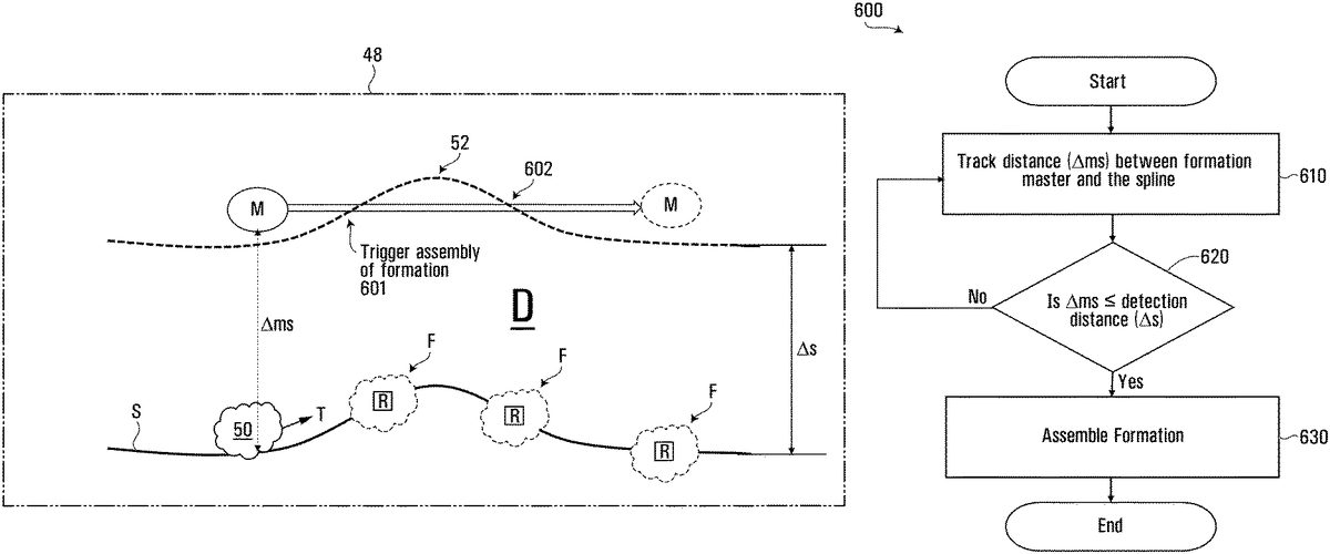
Example conditions under which assembly of a given formation F takes place can be described with reference toFIG.6A, which is a plan view of another embodiment of a spline (denoted as S) surrounded by a boundary48defining the three-dimensional virtual environment24. A group of NPCs50following the spline S along a trajectory T is also shown inFIG.6A.
The game engine14is configured to execute a detection algorithm600for detecting when the formation master M (e.g., the PC) enters within a certain detection zone (denoted “D”) surrounding the spline S. See, for example, point601inFIG.6A.
The detection zone D surrounding the spline S may be characterized by a detection distance Δs, the detection distance Δs being a distance from the spline S at which the spline S is detected by the formation master M. The detection distance Δs may be defined as a unit of length (such as a width, a length, a radius, a diameter etc.) As such, the detection distance Δs defines a boundary52of the detection zone D. The detection distance Δs also defines the width of the spline S.
The detection distance Δs is an indication of whether the formation master M has entered the detection zone such that the given formation F can be assembled. Thus, the detection distance Δs may define a threshold value (of the distance between the formation master and the spline) below which the NPCs are assembled into a formation F and begin start following the formation master M.
With reference toFIG.6B, the detection algorithm600includes a step of tracking a value representing a distance Δms between the formation master M and the spline S. At step620, the value representing the distance Δms is compared to the value representing the detection distance Δs. If the value representing the distance Δms is less than or equal to the value representing the detection distance Δs, the NPCs are assembled into a formation F at step630. If the distance Δms is greater than the distance Δs, the NPCs do not assemble into a formation.
As such, once the formation master M has entered the detection zone D surrounding the spline S, the game engine14may trigger assembly of a certain number of the NPCs into a formation F with a formation reference point R. Thus, once the formation master M has entered the detection zone D surrounding the spline S, the given formation F is triggered, and formation reference point R is created.
The detection distance Δs may be configured to render more natural-looking “following” motion. In one example, the detection distance Δs may be set to a smaller value when the virtual environment24comprises a narrow space (alley, corridor etc.). Setting a smaller value for the detection distance Δs in this instance may prevent the formation master M from being detected on one side of the narrow space while preventing assembly of a given formation F on the other side of this narrow space.
The detection distance Δs may be combined with any of the parameters46previously discussed in order to control the movement of a given formation F and yield more natural-looking motion.
In the present embodiment, once the formation master M has entered the detection zone D and the given formation F has been assembled, the formation reference point R (e.g., the formation center) is then constrained to stay on the spline S as the formation master M moves while the formation master M is not constrained to stay on the spline S.
In other embodiments, the formation reference point R may not be constrained to stay on the spline S as the formation master M moves. In one non-limiting example of implementation, a parameter465designating a “lateral spring distance” value may be defined such that the center of formation R may be shifted laterally from the spline S by a designated value (e.g. representing a unit of length). Thus, the formation reference point R may be laterally offset from the spline S. Given that the formation master M is not constrained to move along the spline S, the lateral offset of the formation reference point R may allow improved follow means by the given formation F should the formation master M move away from the spline S. This may render following motion that may be described as ‘reactive’ and ‘elastic’, and more natural-looking.
Other parameters46imay also be defined in order to render the “following” motion that is more natural-looking, in response to movement of the formation master M.
For a given formation type FTi, each position P1. . . P6may be associated with at least one “role” as listed in a “position role descriptor table”60for that formation type FTi.FIG.7shows an example of a position role descriptor table60for formation types FT1through FT4, which indicates, for each of the six positions P1through P6, a designated role650for that position Pi.
In addition, each of the characters30i(e.g., NPCs) on a given spline also has at least one designated role652(see NPC role descriptor table64inFIG.8B, to be described later in this document).
The fact that both the positions Piand the characters30ieach have a designated role650,652restricts which characters30ican ultimately be placed in which positions Piof a given formation F. An algorithm (to be described later) takes care of matching positions Piwith characters30iby ensuring that, for an entire set of positions P, the designated role of each given position650is matched (or almost matched) by the designated role652of whichever character30iultimately occupies that position Pi.
Examples of “roles”650,652(which are basically tags) can be based on a variety of factors, such as emotional characteristic (e.g., angry, intimate, etc.), story role (e.g., sidekick, antagonist, etc.) or relative spatial position (e.g., right, left, close, lead, forward, etc.). In some cases, the role650,652may have a deliberately broad significance (e.g., “close”); this may provide flexibility to the end users (the level designers) when matching characters30ito positions Pi.
In an example, a specific position Pithat is at the front of the formation F1may be associated with the role650“forward”. In one embodiment, a character30ialso having the role652“forward” would occupy this position Piand therefore will be at the front of the formation F1, even if the master is behind the front of the formation F1. However, in another embodiment (and according to a different interpretation of the term “forward”), a character30ialso having the role “forward” would not occupy the specific position Piunless the formation master M were ahead of the formation F1. In an example, the specific position Pimay be associated with the role650“forward”, regardless of whether the formation is moving forwards or backwards. In another example, the specific position Pimay be associated with the role650“forward” only if the formation is moving forwards.
Another example of a role could be “free”. When a particular position's designated role650is “free”, this is used to indicate that selection of the character30ioccupying this position Piwill not be based on the character's designated role652. It may be preferable to match a character30ito this position Piafter characters30ihave been matched to other positions Pi(whose designated role650is not “free”).
Note also that the position role descriptor table60may include a column660marked as “Must Fit Role Exactly”. The entry in this column660, for a given position Piassociated with a specific role650, indicates whether, in order for a character30ito occupy that position Pi, such character30imust be associated with the specific role650or not. If no character30ion a given spline is marked as being associated with the specific role650for the given position Pi, then the given position Piin the given formation F will be unoccupied.
The position role descriptor table60for each given formation type FTimay be stored as game data22in the memory16.
In other embodiments, each position P1. . . P6may be associated with more than one allowable role as listed in the position role descriptor table60i.
As shown inFIG.8B, a set of allowable formation types {FTi} for a given spline, together with the position role descriptor table60for each allowable formation type FTi, may be referred to as a “formation strategy”66for the given spline. The formation strategy 66 may be stored as game data22in the memory16.
FIG.8Bshows a table that stores the formation strategy 66 for various splines, including the spline S defined from point A to point A′. It is noted that the formation strategy 66 for the spline S includes a set of four formation types FT1, FT2, FT3and FT4(and their respective position role descriptor tables60), as well as the NPC role descriptor table64, to be described below. (In the interest of brevity, only the position role descriptor tables60for formation types FT1and FT4are illustrated in some detail in the illustrated example.)
Assume now that a group of NPCs50is to be assembled into a given formation F as described above with reference to the detection algorithm600. The NPCs in the group may each be associated with a designated role652as defined in a “NPC role descriptor table”64. With continued reference toFIG.8B, an example of an NPC role descriptor table64is shown, which indicates, for each of the five NPCs, NPC1through NPC5as listed in column Actor ID654, a designated role652for that NPC. Examples of roles652have been given above. One difference, however, is that a given NPC associated with the role652“free” (i.e., when the term “free” appears in the NPC role descriptor table64for the given NPC) means that the given NPC may occupy any position Pi, irrespective of the role650associated with that position Piin the position role descriptor table60. The NPC role descriptor table64may be stored as part of the game data22in the memory16.
Clearly, some matching is required between the roles650associated with the positions Piof a given formation type FTi(as encoded by the position role descriptor table60) and the roles652associated with the NPCs (in the NPC role descriptor table64). This will now be described in greater detail.
Initial Selection of Formation
Having determined that a group of NPCs50is to be assembled into an initial formation Fi, the game engine14is configured to execute a formation selection/matching algorithm900to answer the following key considerations: (I) which formation type to select from the formation strategy 66 (when the formation strategy 66 includes a set of more than one “candidate” formation type {FTi}) and (II) in what positions Pi(e.g., P1. . . P6) to place the various NPCs (e.g., NPC1. . . NPC5). As such, the formation selection/matching algorithm900(i.e. the mapping algorithm) involves assigning the video game characters30iin the formation F (e.g. NPCs) to a character position Piin the selected formation type based on a match between the roles650associated with the character positions Piof the selected formation type and the roles652associated with the video game characters30iin the formation Fi.
In order to answer the above considerations, the formation selection/matching algorithm takes into consideration of a variety of criteria, which may include the criteria listed below.
Thus, for each candidate formation type FTi, a rating may be established based on:The percentage of positions that would be naturally available/present on the navmesh26Higher percentages are associated with higher ratings: A formation position Piis considered as available/present: if the position Piis currently on the navmesh26based on a current master position PC(the current position of the formation master M); and if the position will be on the navmesh26based on the projected master position Pf(a future position of the master based on his current location, its speed and a projection time).The formation surfaceWider or smaller candidate formation types FTimay garner a higher rating, depending on a definable variable: This is based on the data provided to the strategy 66. Users can feed a spacing curve to the strategy 66 to define if a position far or close from another will have a higher or lower cost (e.g., in terms of computational resources). By default, wider formations F may be weighted as more attractive, but this is not a requirement.How well the position role descriptor table60for the candidate formation type FTimatches with the NPC role descriptor table64For example, if an NPC is associated with a “Front” role, candidate formation types {FTi} having a position Piassociated with a “Front” role may be rated higher than those that do not;The distance from every NPC from their current spatial coordinates XYZ to their hypothetical position Piwithin the candidate formation type FTiCandidate formation types FTiwith smaller such distances may be ranked higher as they require less movement from the NPCs once the formation Fiis created.
Reference is now made to the flowchart inFIG.11showing steps in the formation selection/matching algorithm900executed by the game engine14. At step910, each of the candidate formation types FTiis ranked based on a variety of criteria (as listed above, for example). At step920, the candidate formation type FTiwith the highest ranking is determined and at step930and therefore selected. At step940, video game characters30i(e.g., NPCs) are assigned to character positions Piin the selected formation type FTi.
The selected candidate formation type (e.g., having the highest rating based on the above-described criteria and possibly other criteria) may be referred to as the “optimal formation type”. However, it should be understood that “optimal” does not require strict optimality in a mathematical sense; it simply can refer to a candidate formation type FTideemed to be meet the criteria to a greater degree (or having a higher rating) than at least one other candidate formation type FTi.
The aforementioned information may be summarized by the table shown inFIG.10A, whereby there is a field for a group ID610(a set of NPCs such as NPC1 . . . NPC5), the current formation type620(e.g., FT1, FT2, . . . , in this case FT1), an identification of the formation master M (in this case, the PC), the spatial coordinates of the formation reference point630(in this case, the formation center R), a list of positions associated with the formation type640(e.g., P1. . . P6), and for each position Pi: if it is occupied by an NPC, then the role (e.g., Free, Front, . . . ) of that NPC and its identity (e.g., NPC1 . . . NPC5), or if it is not occupied, the list of allowable roles for that position Pi. With reference toFIG.10B, the selected formation620, the roles650and the characters30iare a function of the formation selection/matching algorithm900. The spatial coordinates XYZ of the formation reference point R is a function of the movement of the formation master M.
Once a given formation F has been created, the formation reference point R may be constrained to stay on the spline S even if the formation master M (e.g., the PC) leaves the detection zone D. In fact, if the formation master M (e.g., the PC) exits the detection zone D and stays outside the detection zone D but has a component of movement along the general direction of the spline S (see, for example, point602inFIG.6A), the formation reference point R (and the formation as a whole) could move commensurately along the spline S.
In other embodiments (not shown inFIG.6A), if the formation master M (e.g., the PC) exits the detection zone D and stays outside the detection zone D but has a component of movement along the general direction of the spline S, the formation reference point R (and the formation F as a whole) may remain in position and not move until the formation master M has entered the detection zone D.
Dynamic Selection of Formation
A key feature of the present disclosure is that, as a given formation F of NPCs moves along a given spline, the formation type FTichanges dynamically to result in a more natural and fluid movement of the given formation F.
One of the factors that has been found to affect the perceived naturalness and fluidity of movement of a formation of NPCs along a given spline is the timing of the change in the formation type FTi.
For example, it has been found that changing the formation type FTibased on anticipated changes in the navmesh26properties may result in a more natural movement of the group of NPCs50along the given spline. The game engine14may carry out a “dynamic formation management process”1100for this purpose.
Specifically, to anticipate changes in the navmesh26properties that may affect what is the selected (or “optimal”) formation type, the game engine14can evaluate changes that take place ahead of the movement of the formation reference point R (e.g., the formation center) in the general direction along the given spline.
In one example, with reference toFIG.13A, the game engine14is configured to identify a point Odalong another embodiment of a spline (denoted S) that is at a fixed distance ΔF ahead of the current spatial coordinates XYZ of the formation reference point R (e.g., the formation center). For instance, ΔF may be 10 meters, 20 meters or 50 meters, to name a few non-limiting possibilities.
In another example, as shown inFIG.14A, the game engine14is configured to identify a point Otalong the spline S that is a certain number of seconds away from the current spatial coordinates XYZ of the formation reference point R (e.g., the formation center), which takes into account the speed of the formation reference point R. To this end, a look-ahead time Δt may be consulted. As such, the point ahead of the formation (i.e., point Ot) is computed based on a speed of travel of the formation and a look-ahead time Δt. The speed of travel of the formation may be considered to be the speed of travel of a reference point of the formation R. The look-ahead time Δt can be fixed or variable stored in the memory16; in an example, it can be 1 second, 5 seconds or 10 seconds, to name a few non-limiting possibilities.
Reference is now made to the flowchart inFIG.12showing steps in the dynamic formation management process1200executed by the game engine14.
It is noted that the combination of the speed of the formation reference point R (e.g., the formation center) along the spline S and the look-ahead time Δt allows the game engine14to compute the point along the spline where the formation reference point R would end up if it were to continue along its current course for an amount of time equivalent to the look-ahead time (hereinafter referred to as a “future point”). This is shown at step1210ofFIG.11.
At step1220, the game engine14then determines the navmesh26properties at this future point. At step1230, the game engine14decides whether the formation type FTican remain the same or should be changed. For example, the game engine14may re-run the previously described formation selection/matching algorithm900based on the “future point” and see whether the “optimal” formation type resulting from this computation corresponds to the current formation type FTi.
If yes, the formation type FTineed not be changed.
If no, the formation type FTiis changed to the optimal formation type.
The previously discussed criteria may be used by the formation selection/matching algorithm900in order to change the formation type of the formation F from a first formation type FTf(which may be the initial formation type FTi) to a second formation type FTs. Each of the first and second formation types FTf, FTshave their own particular characteristics and attributes (e.g. spatial distribution of character positions Pi, width Wiof formation as shown inFIG.5, etc.)
Thus, it is understood that changing the formation type FTifrom the first formation type FTfto the second formation type FTsmay include selecting the second formation type FTsfrom a set of candidate formation types {FTi} based on a ranking of each of the candidate formation types {FTi}, as previously discussed.
As such, selecting the second formation type FTsfrom the set of the candidate formation types {FTi} may be carried out based on a relative width of the spatial distribution of character positions associated with each of the candidate formation types {FTi} if the candidate formation type were selected as the second formation type FTs.
Additionally, selecting the second formation type FTsfrom the set of candidate formation types {FTi} may be carried out based on a relative number of character positions Pithat would remain on the navmesh26if the candidate formation type were selected as the second formation type Fs.
Furthermore, selecting the second formation type FTsfrom the set of candidate formation types {FTi} may be carried out based on a total distance needing to be traveled by one or more of the video game characters30ibetween its character position Piin the first formation type FTfto its corresponding character position Pi′ in the candidate formation type FTiif the candidate formation type were selected as the second formation type FTs.
Also, selecting the second formation type FTsfrom the set of candidate formation types {FTi} may be carried out based on the extent to which the video game characters30icross paths in transitioning between their character positions Piin the first formation type FTfto their corresponding character positions Pi′ in the candidate formation type if the candidate formation type were selected as the second formation type FTs.
Migration of the individual NPCs as they change formation types (i.e., the paths that video game characters30itravel as they transition from the character positions Piin the first formation type FTfto their corresponding character positions Pi′ in the second formation type FTs) may be gradual, over one or several rendered frames.
In some embodiments, the algorithm ofFIG.12is designed to be performed within 0.75 milliseconds, whereas the spline S may be computed in advance, during an initial phase.
In both variants of the dynamic formation management process1200, namely the look-ahead point based on distance and the look-ahead point based on time, an early change in the formation type, i.e., well ahead of the change in the navmesh26characteristics (such a change being denoted by the symbol “6” inFIGS.13A to13CandFIGS.14A to14C, for example), causes motion of the group of NPCs50to be more natural-seeming as changes in terrain characteristics (e.g. elevation, dimensions, path width, etc.) will be anticipated rather than reacted to. Thus, anticipating a change in terrain characteristics of the path at a future point of the formation (e.g. determining that a dimension of the path is different at said point than at a reference point) can render more natural following movement of the given formation F.
This is particularly effective in creating a natural effect when a decrease in path width along the navmesh26is foreseen. This effect is illustrated inFIGS.13A to13CandFIGS.14A to14Cby way of example.
It is also envisaged that the game engine14may maintain a damping memory25for the selected formation type620so as to prevent the selected formation type620from switching too quickly, even if it would be considered more “optimal” to do so.
With reference therefore toFIG.15, it will be appreciated that there has been provided a method for execution by at least one processor12, which comprises a step1510of maintaining a virtual environment24in the memory16, the 3D virtual environment24including a player character PC, a step1520of causing a plurality of video game characters30ito travel along a path in the virtual three-dimensional environment24in a formation F, the formation F having a formation type FTi, the formation type FTibeing a first formation type FTf, a step1530of moving the formation F along the path, a step1540of determining a change in characteristics of the path at a point Od, Otin the virtual three-dimensional environment24that is ahead of the formation; and, in response to step1540, a step1550of changing the formation type FTito a second formation type FTsin advance of the change in characteristics of the path, i.e., at a point in time before the formation reaches the point Od, Ot.
Additional steps may be included in the method as will be discussed below with reference toFIGS.16A,16B,16C,16D and16E.
A step1530A wherein moving the formation F along the path is in response to motion of a master element (formation master M) associated with the group of video game characters30and may include moving a reference point R of the formation F in response to motion of the formation master M.
A step1540A1wherein computing the point ahead of the formation Od, Otmay be based on (i) a speed of travel of the formation; and (ii) a look-ahead time Δt.
A step of1540A2wherein computing the speed of travel of the formation F may include computing the speed of travel of the reference point of the formation R.
A step1540B1wherein determining a change in characteristics of the path at the point Od, Otthat is ahead of the formation F may include determining that a dimension of the path (e.g., width) is different at point Od, Otthan at the reference point (e.g. reference point of the formation R).
A step1540B2wherein determining a change in characteristics of the path at the point Od, Otthat is ahead of the formation F may include determining that the path is narrower at point Od, Otthan at the reference point of the formation R.
A step1550C1wherein assigning the video game characters30iin the formation to a character position Piin the first formation type FTfis based on a match between the roles associated with the character positions650of the first formation type FTfand the roles652associated with the video game characters in the formation.
A step1550C2changing the formation type FT to the second formation type FTsincludes selecting the second formation type FTsfrom a set of candidate formation types {FT} based on a ranking of each of the candidate formation types and associated with respective spatial distributions of character positions Pi.
A step1550C3wherein assigning the video game characters30iin the formation to a character position Piin the second formation type FTsbased on a match between the roles associated with the character positions650of the second formation type FTsand the roles652associated with the video game characters in the formation.
Selecting the second formation type FTsfrom the set of candidate formation types {FTi} is carried out based on:a relative number of character positions Pithat would remain on the navmesh26if the candidate formation type were selected as the second formation type FTs(at step1550D);a relative width W of the spatial distribution of character positions Piassociated with the candidate formation type FTiif the candidate formation type were selected as the second formation type FTs(at step1550D2);a total distance needing to be traveled by one or more of the video game characters30ibetween its character position Piin the first formation type FTfto its corresponding character position Pi′ in the candidate formation type if the candidate formation type were selected as the second formation type FTs(at step1550D3); andthe extent to which the video game characters30icross paths in transitioning between their character positions Piin the first formation type FTfto their corresponding character positions Pi′ in the candidate formation type if the candidate formation type were selected as the second formation type FTs(at step1550D4).
Additional Considerations
Additional features of the game engine may keep movement of the formation natural and improve group cohesion throughout gameplay.
For example, consider the scenario inFIG.9A, where a group50of NPCs (NPC1. . . NPC4) have spatial coordinates (XYZ1. . . XYZ4). Consider also that the formation master (not shown) has entered the detection zone (not shown) and that the game engine14determines that it is time to create a formation with relative positions P1. . . P4with a formation reference point R. Let it be assumed that the NPCs do not have an assigned role650.
As such, each NPC is free to select their own position Piin the formation Fi(for the purposes of this example, it is assumed that all the positions P1. . . P4in the formation are available and are exempt of any matching restrictions). It is therefore conceivable that NPC1will migrate to position P4given that, for example, NPC1happens to be the closest NPC to position P4. It is also conceivable that NPC2may then migrate to position P3if, for example, NPC2happens to be the closest remaining NPC to position P3. This would constrain the available positions to which the other NPCs (NPC3, NPC4) may migrate, which may result in the paths of individual NPCs crossing over as the formation is created. This may result in unnatural and/or undesirable visual artifacts.
The game engine14may be configured to implement features that prevent unnatural crossover between the NPCs. For example, with reference toFIG.9B, consider a barycentric point B of the group of NPCs50and a barycenter B′ of the formation F on a given spline. Let there be defined four “quadrants” (or zones) Zi(i=1, 2, 3, 4) defined with B as the origin and four quadrants (or zones) Z′i(i=1, 2, 3, 4) defined with B′ as the origin. Therefore, the spatial coordinates (XYZ1. . . XYZ4) for each of the NPCs (NPC1. . . NPC4) lies in one of the zones (Z1. . . Z4).
Referring now toFIG.9C, the game engine14may be configured to move the NPCs into positions P1. . . P4in a way that preserves the relative quadrant positions of the NPCs before and after the formation is created. As such, NPC1, which occupies coordinates XYZ1in quadrant Zi, will occupy quadrant Z′1in the formation, NPC2, which occupies coordinates XYZ2in quadrant Z2, will occupy quadrant Z′2in the formation, and so on.
It will be appreciated that in other embodiments, a similar effect can be obtained by respecting the angular order in which the NPCs appear around the barycenter B and the barycenter B′. As such, it has been shown how the game engine14may be designed to prevent the scenario in which an NPC that is at one point “behind” the group suddenly moves in front of the group, by itself, when the formation is created (or when the formation type is changed).
Certain embodiments disclosed herein can be implemented as hardware, firmware, software, or a combination thereof. Moreover, the software may be implemented as an application program tangibly embodied on a program storage unit or computer readable medium consisting of parts, or of certain devices and/or a combination of devices. The application program may be uploaded to, and executed by, a machine comprising any suitable architecture. The machine may be implemented on a computer platform having hardware such as one or more central processing units (“CPUs”) and/or graphics processing units (“GPUs”), a memory, and input/output interfaces. The computer platform may also include an operating system and microinstruction code. The various processes and functions described herein may be either part of the microinstruction code or part of the application program, or any combination thereof, which may be executed by a CPU, whether or not such a computer or processor is explicitly shown. In addition, various other peripheral units may be connected to the computer platform such as an additional data storage unit and a printing unit. Furthermore, a non-transitory computer readable medium is any computer readable medium except for a transitory propagating signal.
The examples and language recited herein are intended for pedagogical purposes to aid the reader in understanding the principles of the disclosed embodiments and concepts, and are to be construed as being without limitation to such specifically recited examples and language. Moreover, statements herein reciting principles, aspects, and embodiments of the disclosed embodiments, as well as specific examples thereof, are intended to encompass both structural and functional equivalents thereof. Additionally, it is intended that such equivalents include both currently known equivalents as well as equivalents developed in the future, i.e., any elements developed that perform the same function, regardless of structure.
It should be appreciated that certain adaptations and modifications of the described embodiments can be made. Therefore, the above discussed embodiments are to be considered illustrative and not restrictive. Also, it should be appreciated that additional elements that may be needed for operation of certain embodiments of the present invention have not been described or illustrated as they are assumed to be within the purview of the person of ordinary skill in the art. Moreover, any feature of any embodiment discussed herein may be combined with any feature of any other embodiment discussed herein in some examples of implementation. Moreover, certain embodiments of the present invention may be free of, may lack and/or may function without any element that is not specifically disclosed herein.
Claims
- A computer-implemented method, comprising: maintaining a virtual three-dimensional environment;assembling a plurality of video game characters into a formation, each of the plurality of video game characters having a character type and a position in the virtual three-dimensional environment defined by spatial coordinates, the formation having a reference point and a formation type, the formation type being a first formation type;moving the formation along a path in the virtual three-dimensional environment in response to motion of a master element associated with the plurality of video game characters, wherein moving the formation along the path comprises moving the reference point of the formation in response to motion of the master element such that spatial coordinates of the reference point are determined as a function of the motion of the master element and wherein the function is defined by one or more parameters, each of the one or more parameters designating a characteristic of motion of the formation and comprising a value;responsive to determining a change in characteristics of the path at a point in the virtual three-dimensional environment that is ahead of the formation, changing the formation type to a second formation type in advance of the change in characteristics of the path.
- The method defined in claim 1, further comprising computing the point ahead of the formation based on a speed of travel of the formation and a look-ahead time.
- The method defined in claim 2, further comprising computing the speed of travel of the formation by computing a speed of travel of a reference point of the formation.
- The method defined in claim 3, wherein the reference point of the formation is a center point or centroid of the formation.
- The method defined in claim 1, wherein one of the parameters is a damping parameter.
- The method defined in claim 1, wherein determining a change in characteristics of the path at the point that is ahead of the formation comprises determining that a dimension of the path is different at said point than at the reference point of the formation.
- The method defined in claim 1, wherein the first formation type is characterized by a first width and the second formation is characterized by a second width different than the first width.
- The method defined in claim 1, wherein the first formation type defines a first spatial distribution of character positions and the second formation type defines a second spatial distribution of character positions.
- The method defined in claim 8, wherein each of the character positions of the first formation type and of the second formation type is associated with at least one role.
- The method defined in claim 1, wherein each of the video game characters is associated with at least one role.
- The method defined in claim 10, further comprising assigning the video game characters in the formation to a character position in the first formation type based on a match between roles associated with the character positions of the first formation type and the roles associated with the video game characters in the formation.
- The method defined in claim 10, further comprising assigning the video game characters in the formation to a character position in the second formation type based on a match between the roles associated with the character positions of the second formation type and the roles associated with the video game characters in the formation.
- The method defined in claim 1, wherein the first formation type defines a first set of relative character positions of the video game characters in the formation and the second formation type defines a second set of relative character positions of the video game characters in the formation.
- The method defined in claim 1, wherein the path is located on a navigation mesh.
- The method defined in claim 1, wherein the reference point of the formation is constrained to stay on a spline.
- The method defined in claim 15, wherein the master element is not constrained to stay on the spline.
- The method defined in claim 1, wherein changing the formation type to the second formation type includes selecting the second formation type from a set of candidate formation types based on a ranking of each of the candidate formation types.
- The method defined in claim 1, wherein changing the formation type to the second formation type includes selecting the second formation type from a set of candidate formation types associated with respective spatial distributions of character positions.
- The method defined in claim 18, wherein the path is located on a navigation mesh, wherein selecting the second formation type from the set of candidate formation types is carried out based on a relative number of character positions that would remain on the navigation mesh if the candidate formation type were selected as the second formation type.
- The method defined in claim 18, wherein selecting the second formation type from the set of candidate formation types is carried out based on a relative width of the spatial distribution of character positions associated with the candidate formation type if the candidate formation type were selected as the second formation type.
- The method defined in claim 18, wherein selecting the second formation type from the set of candidate formation types is carried out based on a total distance needing to be traveled by one or more of the video game characters between its character position in the first formation type to its corresponding character position in the candidate formation type if the candidate formation type were selected as the second formation type.
- The method defined in claim 18, wherein selecting the second formation type from the set of candidate formation types is carried out based on an extent to which the video game characters cross paths in transitioning between their character positions in the first formation type to their corresponding character positions in the candidate formation type if the candidate formation type were selected as the second formation type.
- The method defined in claim 1, wherein the master element is a playing character of the video game.
- The method defined in claim 1, wherein the master element is an element other than a playing character of the video game.
- The method defined in claim 1, wherein the first and second formation types are stored in a memory.
- The method defined in claim 1, wherein determining a change in characteristics of the path at the point that is ahead of the formation comprises determining that the path is narrower at said point than at the reference point of the formation.
- A non-transitory computer-readable storage medium comprising computer-readable instructions which, when read and executed by at least one processor, cause the at least one processor to execute a method that comprises: maintaining a virtual three-dimensional environment;assembling causing a plurality of video game characters into a formation, each of the plurality of video game characters having a character type and a position in the virtual three-dimensional environment defined by spatial coordinates, the formation having a reference point and a formation type, the formation type being a first formation type;moving the formation along a path in the virtual three-dimensional environment in response to motion of a master element associated with the plurality of video game characters, wherein moving the formation along the path comprises moving the reference point of the formation in response to motion of the master element such that spatial coordinates of the reference point are determined as a function of the motion of the master element and wherein the function is defined by one or more parameters, each of the one or more parameters designating a characteristic of motion of the formation and comprising a value;and responsive to determining a change in characteristics of the path at a point in the virtual three-dimensional environment that is ahead of the formation, changing the formation type to a second formation type in advance of the change in characteristics of the path.
- An apparatus comprising: at least one processor;a memory storing data and instructions, the data representing a virtual three-dimensional environment;and an interface through which a user provides input and receives output, wherein the at least one processor is configured to execute the instructions in the memory for implementing a computer program that generates the output in response to the received input and, the computer program including at least one process that comprises: assembling a plurality of video game characters into a formation, each of the plurality of video game characters having a character type and a position in the virtual three-dimensional environment defined by spatial coordinates, the formation having a reference point and a formation type, the formation type being a first formation type;moving the formation along a path in the virtual three-dimensional environment in response to motion of a master element associated with the plurality of video game characters, wherein moving the formation along the path comprises moving the reference point of the formation in response to motion of the master element such that spatial coordinates of the reference point are determined as a function of the motion of the master element and wherein the function is defined by one or more parameters, each of the one or more parameters designating a characteristic of motion of the formation and comprising a value;and responsive to determining a change in characteristics of the path at a point in the virtual three-dimensional environment that is ahead of the formation, changing the formation type to a second formation type in advance of the change in characteristics of the path.
Disclaimer: Data collected from the USPTO and may be malformed, incomplete, and/or otherwise inaccurate.