U.S. Pat. No. 11,617,950
GRAPHICAL INDICATOR FOR VIDEO GAMES
AssigneeSquare Enix Ltd.
Issue DateNovember 18, 2020
Illustrative Figure
Abstract
A video game that is progressed by controlling a character operated by a player in a virtual game world in which the character is vulnerable to attack. A computer apparatus functions as: an attack analysing unit configured to determine a direction of an incoming attack, and an intensity of the incoming attack or a level of damage inflicted upon the character as a consequence of the incoming attack; and a graphical indicator generating unit configured to generate an on-screen graphical indicator comprising: a first pointing part arranged to indicate the determined direction of the incoming attack, and a second part arranged to indicate the determined intensity of the incoming attack or the determined level of damage inflicted upon the character as a consequence of the incoming attack; wherein the first pointing part and the second part are joined together to form the graphical indicator.
Description
DETAILED DESCRIPTION OF PREFERRED EMBODIMENTS The present embodiments represent the best ways known to the Applicant of putting the invention into practice. However, they are not the only ways in which this can be achieved. Embodiments of the present invention provide an on-screen graphical indicator that is incorporated within a video game. The video game is provided as a computer program. The computer program may be supplied on a computer-readable medium (e.g. a non-transitory computer-readable recording medium such as a CD or DVD) having computer-readable instructions thereon. Alternatively the computer program may be provided in a downloadable format, over a network such as the Internet, or may be hosted on a server. With reference toFIG.1, the video game program may be executed on a video game apparatus10, such as a personal computer or a video game console. The video game apparatus10comprises a display screen12on which the video game is displayed, and a control unit14which typically includes at least a Central Processing Unit (CPU), a Read Only Memory (ROM) and a Random Access Memory (RAM). The control unit14may also include a Graphics Processing Unit (GPU) and a sound processing unit. The display screen12and the control unit14may be provided in a common housing, or may be separate connected units. The video game apparatus10also includes one or more user input devices by which the user can control a player character in the game. Such a user input device may comprise, for example, a mouse, a keyboard, a hand-held controller (e.g. incorporating a joystick and/or various control buttons), or a touchscreen interface integral with the display screen12(e.g. as in the case of a smartphone or a tablet computer). The video game apparatus10may be connected to a network such as the Internet, or may be stand-alone apparatus that is not connected to a network. Alternatively, ...
DETAILED DESCRIPTION OF PREFERRED EMBODIMENTS
The present embodiments represent the best ways known to the Applicant of putting the invention into practice. However, they are not the only ways in which this can be achieved.
Embodiments of the present invention provide an on-screen graphical indicator that is incorporated within a video game. The video game is provided as a computer program. The computer program may be supplied on a computer-readable medium (e.g. a non-transitory computer-readable recording medium such as a CD or DVD) having computer-readable instructions thereon. Alternatively the computer program may be provided in a downloadable format, over a network such as the Internet, or may be hosted on a server.
With reference toFIG.1, the video game program may be executed on a video game apparatus10, such as a personal computer or a video game console. The video game apparatus10comprises a display screen12on which the video game is displayed, and a control unit14which typically includes at least a Central Processing Unit (CPU), a Read Only Memory (ROM) and a Random Access Memory (RAM). The control unit14may also include a Graphics Processing Unit (GPU) and a sound processing unit. The display screen12and the control unit14may be provided in a common housing, or may be separate connected units. The video game apparatus10also includes one or more user input devices by which the user can control a player character in the game. Such a user input device may comprise, for example, a mouse, a keyboard, a hand-held controller (e.g. incorporating a joystick and/or various control buttons), or a touchscreen interface integral with the display screen12(e.g. as in the case of a smartphone or a tablet computer). The video game apparatus10may be connected to a network such as the Internet, or may be stand-alone apparatus that is not connected to a network.
Alternatively, with reference toFIG.2, the video game program may be executed within a network-based video game system20. The video game system20comprises a server device22, a communication network24(e.g. the Internet), and a plurality of user terminals26operated by respective users. The server device22communicates with the user terminals26through the communication network24. Each user terminal26may comprise a network-connectable video game apparatus10as described above, such as a personal computer or a video game console, or a smartphone, a tablet computer, or some other suitable piece of user equipment. The video game program may be executed on the server22, which may stream user-specific game content (e.g. video in real time) to each of the plurality of user terminals26. At each user terminal the respective user can interact with the game and provide input that is transmitted to the server22, to control the progress of the game for the user. Alternatively, for a given user, the video game program may be executed within the respective user terminal26, which may interact with the server22when necessary.
In either case, the video game progresses in response to user input, with the user input controlling a player character. The user's display screen may display the player character's field of view in the game world in a “first-person” manner, preferably in three dimensions, and preferably using animated video rendering (e.g. photorealistic video rendering in particular), in the manner of a virtual camera.
Alternatively, the user's display screen may display the player character and other objects or characters in the game world in a “third-person” manner, again preferably in three dimensions, and preferably using animated video rendering (e.g. photorealistic video rendering in particular), in the manner of a virtual camera.
FIG.3is a block diagram showing the configuration of the video game apparatus10shown inFIG.1, in the case of the game being executed on such apparatus. It will be appreciated that the contents of the block diagram are not exhaustive, and that other components may also be present.
As illustrated, the control unit14of the video game apparatus10includes an input device interface102to which an input device103(e.g. a mouse, a keyboard or a hand-held controller, e.g. incorporating a joystick and/or various control buttons, as mentioned above) is connected, a processor (e.g. CPU)104, and an image generator (e.g. GPU)111to which a display unit12is connected.
The control unit14also includes memory (e.g. RAM and ROM)106, a sound processor107connectable to a sound output device108, a DVD/CD-ROM drive109operable to receive and read a DVD or CD-ROM110(both being examples of a computer-readable recording medium), a communication interface116connectable to the communication network24(e.g. the Internet), and data storage means115via which data can be stored on a storage device (either within or local to the video game apparatus10, or in communication with the control unit14via the network24). For a stand-alone (not network connected) video game apparatus, the communication interface116may be omitted.
The video game program causes the control unit14to take on further functionality of a virtual camera control unit112, an attack analysing unit105and an indicator generating unit113.
An internal bus117connects components102,104,105,106,107,109,111,112,113,114,115and116as shown.
FIG.4is a block diagram showing the configuration of the server apparatus22shown inFIG.2, in the case of the game being executed within a network-based video game system. It will be appreciated that the contents of the block diagram are not exhaustive, and that other components may also be present.
As illustrated, the server apparatus22includes a processor (e.g. CPU)204, and an image generator (e.g. GPU)211, memory (e.g. RAM and ROM)206, a DVD/CD-ROM drive209operable to receive and read a DVD or CD-ROM210(both being examples of a computer-readable recording medium), a communication interface216connected to the communication network24(e.g. the Internet), and data storage means215via which data can be stored on a storage device (either within or local to the server apparatus22, or in communication with the server apparatus22via the network24).
The video game program causes the server apparatus22to take on further functionality of a virtual camera control unit212, an attack analysing unit205and an indicator generating unit213.
An internal bus217connects components204,205,206,209,211,212,213,214,215and216as shown.
Via the communication interface216and the network24, the server apparatus22may communicate with a user terminal26(e.g. video game apparatus10) as mentioned above, during the course of the video game. Amongst other things, the server apparatus22may receive user input from the input device103of the video game apparatus10, and may cause video output to be displayed on the display screen12of the video game apparatus10.
Attack Analysis and Graphical Indicator Generation
Throughout the course of the video game the player character may be subject to incoming attacks from enemy characters within the game world. Such attacks may come from a number of different directions relative to the direction in which the player character is facing or moving, and may come from an enemy character who is visible to the user (i.e. on-screen) or who is invisible to the user (e.g. off-screen, or concealed behind an object on-screen, or behind the player character). In the present disclosure the incoming attack is generally exemplified as being gunfire (i.e. bullets). However, depending on the subject of the video game, a different form of attack may take place, such as projectile attack (e.g. arrows launched by archers, in the case of a game set in a medieval period).
To improve a player's awareness of the threat that an incoming attack represents to the player character's life, and to enable them to take evasive or retaliatory action as appropriate, embodiments of the invention provide on-screen graphical indicators, each of which indicates both the direction of the incoming attack and either the intensity of the incoming attack or a level of damage inflicted upon the player character as a consequence of the incoming attack. With regard to the concept of “level of damage inflicted upon the character”, it will of course be appreciated that, in video games, a player character is usually able to receive a number of hits that progressively weaken the character before the character is killed or loses a life.
In more detail, and as shown for example inFIGS.5-7andFIGS.8a-8c, a first (presently-preferred) embodiment of an on-screen graphical indicator500comprises a first pointing part501that is joined to an arc-shaped second part502. The first pointing part501is arranged to indicate the direction of the incoming attack (the attack being illustrated by bullets506inFIGS.5and6). The second part502is arranged to indicate the intensity of the incoming attack506or, alternatively, a level of damage inflicted upon the player character504as a consequence of the incoming attack506.
Reference will now be made in passing to the procedural flow diagram inFIG.18, which illustrates an attack analysing and graphical indicator generating routine1800according to embodiments of the invention. To generate the graphical indicator500during the course of the game the attack analysing unit105/205(as described above in relation toFIGS.3and4) analyses1801the incoming attack506and determines1802the direction of the incoming attack. The concept of “direction of the incoming attack” will be explained in greater detail below.
The attack analysing unit105/205also determines1803the intensity of the incoming attack506or, alternatively, a level of damage inflicted upon the player character504as a consequence of the incoming attack506. The alternative concepts of “intensity of the incoming attack” and “level of damage inflicted upon the player character as a consequence of the incoming attack” will also be explained in greater detail below. Depending on the setup of the game, the user may be able to choose (e.g. via a “preferences” menu) one of these two alternatives to be analysed and indicated by means of the graphical indicator. Alternatively, only one of these alternatives may be used in a particular game, as governed by the game software.
Using information provided by the attack analysing unit105/205, the graphical indicator generating unit113/213then generates1804the on-screen graphical indicator500comprising the first pointing part501joined to the second part502. More particularly, the graphical indicator generating unit113/213dynamically configures1805the angle of the first pointing part501(i.e. the angular direction on-screen in which the first pointing part501points) to indicate the determined direction of the incoming attack (i.e. as determined by the attack analysing unit105/205).
The graphical indicator generating unit113/213also dynamically configures1806the second part502to indicate the intensity of the incoming attack506or, alternatively, the determined level of damage inflicted upon the player character504as a consequence of the incoming attack506(i.e. as determined by the attack analysing unit105/205). Such configuration of the second part502may take a variety of forms, as explained in greater detail below. For instance, the second part502may change in length or size, or in some other visual manner (such as colour), to indicate the intensity of the incoming attack506or, alternatively, the determined level of damage inflicted upon the player character504as a consequence of the incoming attack506.
The attack analysing process and the process of generating the graphical indicator500is carried out as a background routine within the overall game. In presently-preferred implementations the generation of the graphical indicator is continuous and dynamically adjusted whenever the player character is under attack. More particularly, the angle of the first part501and the configuration of the second part502are dynamically adjusted as the attack on the player character changes in direction and/or intensity, or as the level of damage inflicted upon the player character changes during the attack. Accordingly, the player is provided with an instantaneous representation of the attack they are under. Naturally, if the attack is continuous in its direction and/or intensity, the graphical indicator may maintain its configuration for the duration of the attack.
In alternative implementations the graphical indicator500may be generated only for short discrete moments during the gameplay, for example only at the start of an attack.The Concept of “Direction of the Incoming Attack”
In many instances, an incoming attack may follow a linear trajectory from the enemy character to the player character. This is the case with gunfire, laser fire, etc. In such cases, the direction of the incoming attack is the direction of the enemy character from the player character.
However, in other cases, the direction of the incoming attack may be a direction of impact of the attack on the player character (and not necessarily the direction of the enemy character itself). This may be the case if the player character is under fire from projectiles such as arrows or stones that do not follow a linear trajectory.
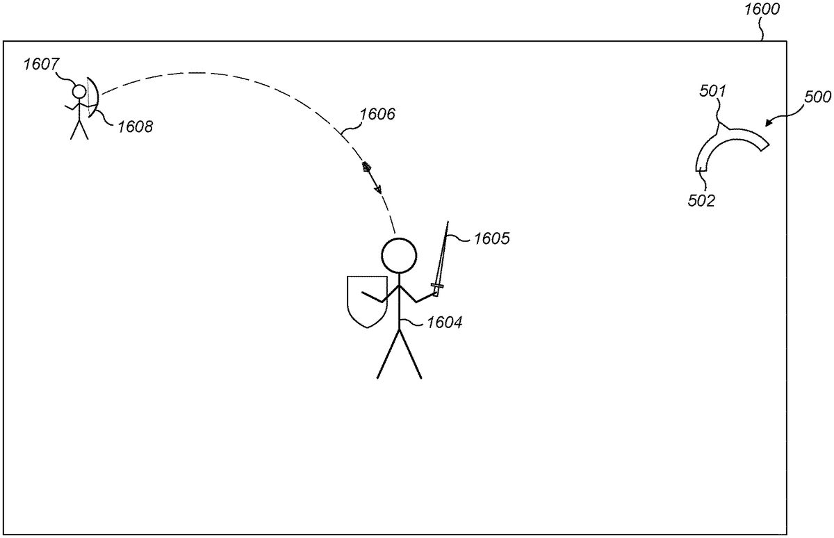
To illustrate such a situation,FIG.16schematically depicts a screenshot1600, from a “third person” perspective, of a player character1604(in this case bearing a sword1605and a shield) that is under attack from an enemy character1607(in this case an archer equipped with a bow1608). As illustrated, the incoming attack1606is in the form of a launched projectile, namely an arrow from the archer, that follows a parabolic trajectory. Since the trajectory is non-linear, the direction of impact of the arrow on the player character1604will be different from the direction of the enemy character1607from the player character1604. To convey this, the first pointing part501of the graphical indicator500indicates the direction of impact of the attack on the player character1604, rather than the direction of the enemy character1607from the player character1604. This may be helpful to the user as they may prefer to take action to evade or defend themselves from the incoming attack1606, e.g. by moving the shield in accordance with the indicated direction of impact, to block the attack, rather than say attempting to shoot back at the enemy character1607. Consequently, in such a situation, the graphical indicator500conveying the direction of impact of the attack1606on the player character1604may be more useful to the user than the direction of the enemy character1607itself.The Concepts of “Intensity of the Incoming Attack” and “Level of Damage Inflicted Upon the Player Character as a Consequence of the Incoming Attack”
The concepts of “intensity of the incoming attack” and “level of damage inflicted upon the player character as a consequence of the incoming attack” may be embodied by, but not limited to, any of the following:the instantaneous intensity of the incoming attack (e.g. proportional to the number of incoming bullets or other projectiles fired at the player character per unit of time);the level of damage the attack is potentially capable of causing the player character (if defensive or retaliatory action is not taken);the instantaneous level of damage being absorbed by the player character (i.e. taking into account the effect of any shield or other defensive means possessed by the player character);the total level of damage absorbed by the player character over a period of gameplay (e.g. since the attack or battle began);the total level of damage absorbed by the player character since the beginning of the game.
Indicating Direction and Intensity
To describe the first embodiment of the invention in more detail, and to exemplify some of the principles introduced above, reference will now be made toFIGS.5-7andFIGS.8a-8c, which all depict an on-screen graphical indicator500in which the second part502is arc-shaped. Reference will also be made toFIG.17, which is an annotated and simplified version ofFIG.5, to illustrate geometrical aspects of the graphical indicator500.
More particularly,FIGS.5-7depict a series of schematic screenshots510of various scenes in a virtual world of a “first-person shooter” video game in which the player character504is carrying a gun505. In practice, such video screens may be generated by the image generator111/211and virtual camera control unit112/212, under the control of processor104/204(seeFIGS.3and4). It will of course be appreciated that, in the presentFIGS.5-7, black and white line drawings are used to represent what would typically be displayed to the user as rendered video (preferably photorealistic video rendering) in the game.
In the depicted screenshots510, the player character504is under attack by an enemy character507who is carrying a gun508. Thus, the attack to which the player character504is subjected is gunfire—i.e. a stream of bullets506fired by the enemy character507towards the player character.
The on-screen graphical indicator500comprises two conjoined parts: a first pointing part501and a second part502. In the illustrated embodiment the first pointing part501comprises an arrowhead and is arranged to indicate the determined direction of the incoming attack506, whereas the second part502comprises an arc and is configured to indicate, by means of the length of the arc, the determined intensity of the incoming attack506or the determined level of damage inflicted upon the player character504as a consequence of the incoming attack.
To indicate the determined direction of the incoming attack506, and with reference to the annotated and simplified diagram inFIG.17, the graphical indicator generating unit113/213is configured to adjustably set the angular position1714of the first pointing part501relative to a reference position1712which corresponds to a straight-ahead direction1711of the player character504. In such a manner, the angular position1714of the first pointing part501, at an angle θ from the reference position1712, corresponds to the direction1713of the incoming attack506relative to the straight-ahead direction1711of the player character504, at the same angle θ.
In the illustrated embodiment the arc of the second part502is an arc of a virtual circle, with the first pointing part501pointing outward from the midpoint of the arc. The graphical indicator generating unit113/213is configured to adjustably set the angular position of the first pointing part501on the circumference of the virtual circle, according to the determined direction of the incoming attack506, with the arc-shaped second part502extending on both sides of the first pointing part501, also on the circumference of the virtual circle. The centre of the virtual circle is indicated by “O” inFIG.17, which also corresponds to the point of intersection of the virtual lines denoting the reference position1712and the angular position1714of the first pointing part501.
In the illustrated embodiment the arrowhead501points outward from the outer (convex) face of the arc502. However, in alternative embodiments, the arrowhead501may point inwards from the inner (concave) face of the arc502, in an equivalent angular position.
The graphical indicator generating unit113/213is configured to adjustably set the length of the arc502in dependence on the determined intensity of the incoming attack or the determined level of damage inflicted upon the player character504as a consequence of the incoming attack.
In the instance of gameplay shown inFIG.5the incoming attack506is of a relatively high intensity (denoted by the relatively high frequency of bullets in the illustration) and is originating from an off-screen enemy character507. That is to say, the enemy character507is not visible to the user at this moment in the game, and is illustrated outside the screenshot510inFIG.5merely for the sake of explanation. The enemy character507is located in a direction in front of the player character504and to the right of the direction the player character is facing.
Accordingly, in this instance the arrowhead501of the graphical indicator500is pointed upwards and to the right, to indicate the direction of the incoming attack506, and the arc502is relatively long to indicate the relatively high intensity of the incoming attack506.
Although the bullets of the incoming attack506are shown in this schematic screenshot for reference, in the actual gameplay they may not be visible to the user. The indicator500may therefore be the only indication to the player of the direction and intensity of the attack the player character is under.
FIG.6shows a further instance of the video game, in which the player character504is in receipt of an incoming attack506of a relatively low intensity (denoted by the relatively low frequency of bullets in the illustration). The attack506of gunfire is incident on the player character504from a direction in front of and to the left of the player character504. This is shown by the graphical indicator500, in which the arrowhead501is directed upwards and to the left, and the length of the arc502is relatively short, to indicate the relatively low intensity of the incoming attack506.
It should be noted that, inFIG.6, the graphical indicator500is in a different position on the screen than inFIG.5. Indeed, the graphical indicator generating unit113/213may be configured to reposition the graphical indicator within the screen, so as not to obscure relevant content (such as the enemy character507inFIG.6).
InFIG.7the incoming attack (not shown) is coming from behind and to the right of the player character504, and is of a relatively low intensity. This is shown by the graphical indicator500, in which the arrowhead501is directed downwards and to the right, and the length of the arc502is relatively short, to indicate the relatively low intensity of the incoming attack.
As can be appreciated fromFIG.7in particular, the graphical indicator500may be the only indication that the user may have that the player character504is under attack—thus illustrating the usefulness of the graphical indicator500to the user.
FIGS.8a,8band8cshow three instances of the graphical indicator500of the first embodiment, as employed inFIGS.5-7, i.e. wherein the second part502comprises an arc (on the circumference of a virtual circle) and the first pointing part501comprises an arrowhead arranged in the midpoint of the arc502.
As noted above, the graphical indicator generating unit113/213is configured to adjustably set the length or size of the arc502in dependence on the determined intensity of the incoming attack or the determined level of damage inflicted upon the player character as a consequence of the incoming attack. In this embodiment, a larger or longer arc502indicates a greater intensity of attack or level of damage.
To illustrate this,FIGS.8ato8crepresent three different levels of intensity of an incoming attack.FIG.8arepresents a relatively low intensity of an incoming attack, denoted by a relatively short length of the arc502;FIG.8brepresents a medium intensity of an incoming attack, denoted by an intermediate length of the arc502; andFIG.8crepresents a relatively high intensity of an incoming attack, denoted by a relatively long length of the arc502. Naturally, as explained above, in practice the graphical indicator500would be dynamically rotated as appropriate, so that the angular position of the first pointing part501indicates the direction of the incoming attack.
As discussed above, in the embodiment ofFIGS.5-7and8a-8cthe second part502of the graphical indicator500comprises an arc of a virtual circle. Alternatively, in other embodiments, the arc may be an arc of another curved virtual shape, such a virtual ellipse.
In further alternative embodiments the second part of the graphical indicator may comprise some other geometric shape or may take some other form, some examples of which will now be described. In all these cases, in practice the graphical indicator would be dynamically rotated as appropriate, so that the angular position of the first pointing part indicates the direction of the incoming attack.Perpendicular Line Indicator
FIGS.9a,9band9cillustrate a second embodiment of a graphical indicator900having a first pointing part901joined to a second part902. The second part902is elongate, in the form of a line or bar arranged substantially perpendicularly to the pointing direction of the first pointing part901. In this embodiment the first pointing part901is also an arrowhead and is located at the midpoint of the perpendicular line902.
Similar to the first embodiment, the graphical indicator generating unit113/213is configured to adjustably set the length or size of the second part902in dependence on the determined intensity of the incoming attack or the determined level of damage inflicted upon the player character as a consequence of the incoming attack. In this embodiment, a larger or longer line902indicates a greater intensity of attack or level of damage.
To illustrate this,FIGS.9ato9crepresent three different levels of intensity of an incoming attack.FIG.9arepresents a relatively low intensity of an incoming attack, denoted by a relatively short length of the line902;FIG.9brepresents a medium intensity of an incoming attack, denoted by an intermediate length of the line902; andFIG.9crepresents a relatively high intensity of an incoming attack, denoted by a relatively long length of the line902.Parallel Line Indicator
FIGS.10a,10band10cillustrate a third embodiment of a graphical indicator1000having a first pointing part1001joined to a second part1002. The second part1002is elongate, in the form of a line or bar arranged substantially parallel to the pointing direction of the first pointing part1001. In this embodiment the first pointing part1001is an arrowhead and is located at one end of the second part1002.
Similar to the first and second embodiments, the graphical indicator generating unit113/213is configured to adjustably set the length or size of the second part1002in dependence on the determined intensity of the incoming attack or the determined level of damage inflicted upon the player character as a consequence of the incoming attack. In this embodiment, a larger or longer line1002indicates a greater intensity of attack or level of damage.
To illustrate this,FIGS.10ato10crepresent three different levels of intensity of an incoming attack.FIG.10arepresents a relatively low intensity of an incoming attack, denoted by a relatively short length of the line1002;FIG.10brepresents a medium intensity of an incoming attack, denoted by an intermediate length of the line1002; andFIG.10crepresents a relatively high intensity of an incoming attack, denoted by a relatively long length of the line1002.Segmented Line Indicator
The second part of the line-based graphical indicators ofFIGS.8a-8c,9a-9cand10a-10cmay be graphically divided into segments or provided with other graduations, to give the user an even more quantitative appreciation of the intensity of the incoming attack or the level of damage inflicted upon the player character as a consequence of the incoming attack.
By way of example,FIGS.11a,11band11cillustrate a fourth embodiment of a graphical indicator1100having a first pointing part1101joined to a second part1102, that is a segmented version of the indicator1000ofFIGS.10a,10band10c. Thus, the second part1102of the indicator1100is in the form of a segmented line or bar arranged substantially parallel to the pointing direction of the first pointing part1101.
Similar to the preceding embodiments, the graphical indicator generating unit113/213is configured to adjustably set the length or size of the second part1102in dependence on the determined intensity of the incoming attack or the determined level of damage inflicted upon the player character as a consequence of the incoming attack. In this embodiment, a larger or longer line1102indicates a greater intensity of attack or level of damage.
To illustrate this,FIGS.11ato11crepresent three different levels of intensity of an incoming attack.FIG.11arepresents a relatively low intensity of an incoming attack, denoted by a relatively short length (i.e. a single segment) of the segmented line1102;FIG.11brepresents a medium intensity of an incoming attack, denoted by an intermediate length (two segments) of the line1102; andFIG.11crepresents a relatively high intensity of an incoming attack, denoted by a relatively long length (three segments) of the line1102.Shaded Indicator
FIGS.12a,12band12cshow a fifth embodiment of a graphical indicator1200having a first pointing part1201joined to a second part1202. The second part1202is substantially circular (although it could be any other shape) and is provided with shading. The first pointing part1201is again an arrowhead.
In this case, the graphical indicator generating unit113/213is configured to adjustably set the density of shading of the second part1202in dependence on the determined intensity of the incoming attack or the determined level of damage inflicted upon the player character as a consequence of the incoming attack. In this embodiment, a higher density of shading of the second part1202indicates a greater intensity of attack or level of damage.
To illustrate this,FIGS.12ato12crepresent three different levels of intensity of an incoming attack.FIG.12arepresents a relatively low intensity of an incoming attack, denoted by a relatively low density of shading of the second part1202;FIG.12brepresents a medium intensity of an incoming attack, denoted by an intermediate density of shading of the second part1202; andFIG.12crepresents a relatively high intensity of an incoming attack, denoted by a relatively high density of shading of the second part1202.Filled Indicator
FIGS.13a,13band13cshow a sixth embodiment of a graphical indicator1300having a first pointing part1301joined to a second part1302. The second part1302is substantially circular (although it could be any other shape) and is provided with at least partial shading or fill1310. The first pointing part1301is again an arrowhead.
In this case, the graphical indicator generating unit113/213is configured to adjustably set the extent of shading or fill1310of the second part1302in dependence on the determined intensity of the incoming attack or the determined level of damage inflicted upon the character as a consequence of the incoming attack. In this embodiment, a greater extent of shading or fill1310of the second part1302indicates a greater intensity of attack or level of damage.
To illustrate this,FIGS.13ato13crepresent three different levels of intensity of an incoming attack.FIG.13arepresents a relatively low intensity of an incoming attack, denoted by a relatively low extent of shading or fill1310of the second part1302;FIG.13brepresents a medium intensity of an incoming attack, denoted by an intermediate extent of shading or fill1310of the second part1302; andFIG.13crepresents a relatively high intensity of an incoming attack, denoted by a relatively high extent of shading or fill1310of the second part1302.
In a variant which is not shown in the figures, the second part of the graphical indicator (which may be any shape) may change colour. In such a case, the graphical indicator generating unit113/213is configured to adjustably set the colour of the second part in dependence on the determined intensity of the incoming attack or the determined level of damage inflicted upon the player character as a consequence of the incoming attack. For instance, a green colour may indicate a low intensity of attack or a low level of damage, a yellow colour may indicate a medium intensity of attack or a medium level of damage, and a red colour may indicate a high intensity of attack or a high level of damage. The second part of the graphical indicator is joined to a first pointing part as per the earlier embodiments.Numerical Indicator
FIGS.14a,14band14cshow a seventh embodiment of a graphical indicator1400having a first pointing part1401joined to a second part1402. The second part1402comprises a numerical indicator which includes a numerical value (in this case ranging from 1 to 10). The first pointing part1401is again an arrowhead.
In this case, the graphical indicator generating unit113/213is configured to adjustably set the numerical value of the numerical indicator in dependence on the determined intensity of the incoming attack or the determined level of damage inflicted upon the player character as a consequence of the incoming attack.
To illustrate this,FIGS.14ato14crepresent three different levels of intensity of an incoming attack.FIG.14arepresents a relatively low intensity of an incoming attack, denoted by a relatively low numerical value (1) in the second part1402;FIG.14brepresents a medium intensity of an incoming attack, denoted by an intermediate numerical value (6) in the second part1402; andFIG.14crepresents a relatively high intensity of an incoming attack, denoted by a relatively high numerical value (9) in the second part1402.Graphical Image Indicator
FIGS.15a,15band15cshow an eighth embodiment of a graphical indicator1500having a first pointing part1501joined to a second part1502. The overall graphical indicator1500is a graphical image (in this case an archer's arrow), the extent of completeness of which indicates the intensity of the incoming attack or the determined level of damage inflicted upon the player character as a consequence of the incoming attack. The extent of completeness of the indicator1500is thus variable—especially, but not necessarily exclusively, in terms of the appearance of the second part1502. The first pointing part1501is again an arrowhead.
In this case, the graphical indicator generating unit113/213is configured to adjustably set the extent of completeness of the graphical image in dependence on the determined intensity of the incoming attack or the determined level of damage inflicted upon the player character as a consequence of the incoming attack.
To illustrate this,FIGS.15ato15crepresent three different levels of intensity of an incoming attack.FIG.15arepresents a relatively low intensity of an incoming attack, denoted by a relatively low extent of completeness of the second part1502(the absence of fletches);FIG.15brepresents a medium intensity of an incoming attack, denoted by an intermediate extent of completeness of the second part1502(only a few fletches are shown); andFIG.15crepresents a relatively high intensity of an incoming attack, denoted by a relatively high extent of completeness of the second part1502(a full complement of fletches is shown).
Modifications and Alternatives
Detailed embodiments and some possible alternatives have been described above. As those skilled in the art will appreciate, a number of modifications and further alternatives can be made to the above embodiments whilst still benefiting from the inventions embodied therein. It will therefore be understood that the invention is not limited to the described embodiments and encompasses modifications apparent to those skilled in the art lying within the scope of the claims appended hereto.
Claims
- A computer-readable recording medium including a program which is executed by a computer apparatus to provide a video game that is progressed by controlling a character operated by a player in a virtual game world in which the character is vulnerable to attack, the program causing the computer apparatus to function as: an attack analysing unit configured to: determine a direction of an incoming attack as a direction of impact of the attack on the character when the character is under the attack by a projectile that do not follow a linear trajectory, and determine an intensity of the incoming attack or a level of damage inflicted upon the character as a consequence of the incoming attack;and a graphical indicator generating unit configured to generate an on-screen graphical indicator comprising: a first pointing part arranged to indicate the determined direction of the incoming attack, and a second part arranged to indicate the determined intensity of the incoming attack or the determined level of damage inflicted upon the character as a consequence of the incoming attack;wherein the first pointing part and the second part are joined together to form the graphical indicator;wherein the graphical indicator generating unit is configured to adjustably set a dimension or a characteristic of the second part in dependence on the determined intensity of the incoming attack or the determined level of damage inflicted upon the character as a consequence of the incoming attack;wherein the graphical indicator generating unit is further configured to determine a location of the on-screen graphical indicator based on content to be displayed on a screen;and wherein the location of the on-screen graphical indicator is determined by the graphical indicator generating unit to prevent obscuring of a source of the attack by the on-screen graphical indicator on the screen.
- The computer-readable recording medium according to claim 1, wherein the first pointing part comprises an arrowhead.
- The computer-readable recording medium according to claim 1, wherein the graphical indicator generating unit is configured to adjustably set an angular position of the first pointing part relative to a reference position which corresponds to a straight-ahead direction of the character, the angular position of the first pointing part corresponding to the direction of the incoming attack relative to the straight-ahead direction of the character.
- The computer-readable recording medium according to claim 3, wherein the second part comprises an arc, wherein the arc is an arc of a virtual circle, and wherein the graphical indicator generating unit is configured to adjustably set the angular position of the first pointing part on the circumference of the virtual circle.
- The computer-readable recording medium according to claim 1, wherein the second part comprises a geometric shape.
- The computer-readable recording medium according to claim 5, wherein the second part comprises an arc.
- The computer-readable recording medium according to claim 6, wherein the first pointing part is arranged in the midpoint of the arc.
- The computer-readable recording medium according to claim 1, wherein the graphical indicator generating unit is configured to arrange the second part substantially perpendicularly to the pointing direction of the first pointing part.
- The computer-readable recording medium according to claim 1, wherein the characteristic of the second part is a density of shading of the second part in dependence on the determined intensity of the incoming attack or the determined level of damage inflicted upon the character as a consequence of the incoming attack or fill of the second part in dependence on the determined intensity of the incoming attack or the determined level of damage inflicted upon the character as a consequence of the incoming attack.
- The computer-readable recording medium according to claim 1, wherein the characteristic of the second part is a colour of the second part in dependence on the determined intensity of the incoming attack or the determined level of damage inflicted upon the character as a consequence of the incoming attack.
- The computer-readable recording medium according to claim 1, wherein the characteristic of the second part is a numerical value of the numerical indicator in the second part, the numerical value in dependence on the determined intensity of the incoming attack or the determined level of damage inflicted upon the character as a consequence of the incoming attack.
- The computer-readable recording medium according to claim 1, wherein the characteristic of the second part is an extent of completeness of the graphical image in dependence on the determined intensity of the incoming attack or the determined level of damage inflicted upon the character as a consequence of the incoming attack.
- The computer-readable recording medium according to claim 1, wherein the direction of the incoming attack is a direction of impact of the attack on the character.
- The computer-readable recording medium according to claim 1, wherein the attack analysing unit is configured to determine an instantaneous intensity of the incoming attack.
- The computer-readable recording medium according to claim 1, wherein the attack analysing unit is configured to determine the level of damage the attack is capable of causing the character.
- The computer-readable recording medium according to claim 1, wherein the attack analysing unit is configured to determine the instantaneous level of damage being absorbed by the character.
- The computer-readable recording medium according to claim 1, wherein the attack analysing unit is configured to determine the total level of damage absorbed by the character over a period of gameplay.
- The computer-readable recording medium according to claim 1, wherein the first pointing part has a length along a longitudinal direction parallel to a direction in which the incoming attack travels and a width perpendicular to the longitudinal direction, and wherein the second part is elongate in the longitudinal direction, and wherein the adjustable dimension of the second part is in the longitudinal direction.
Disclaimer: Data collected from the USPTO and may be malformed, incomplete, and/or otherwise inaccurate.