U.S. Pat. No. 11,612,812
Video Game Streaming With Dynamic Range Conversion
AssigneeAmazon Technologies, Inc.
Issue DateJune 29, 2021
Illustrative Figure
Abstract
Conversion components may receive game video rendered in high-dynamic-range (HDR) and standard-dynamic-range (SDR) camera video of a game player. The conversion components may provide local video output to a local display and remote video output for network transmission to remote viewers. The SDR camera video may be converted to HDR and provided with HDR game video in the local video output. For HDR network transmission, the HDR game video and converted HDR camera video may be included in the remote video output. For SDR network transmission, the HDR game video may be converted to SDR and provided with the SDR camera video in the remote video output. The game video, camera video and other video feeds may have respective portals in the local and remote video outputs. The local and remote video outputs may have respective visual portal arrangements that may be at least partially different from one another.
Description
DETAILED DESCRIPTION Techniques for video game streaming with dynamic range conversion and selectable portal arrangement are described herein. In some examples, conversion components may be provided that may allow conversion of high-dynamic range (HDR) and/or standard-dynamic range (SDR) video inputs to HDR and/or SDR video outputs. The video inputs may include game video received from a video game as well as camera (e.g., webcam) video received from one or more cameras. The term game video, as used herein, refers to video that is rendered by a video game. The camera video may include video that shows a game player playing, and commentating on, the video game. The video outputs may include a local video output, which is provided to a local display component (e.g., television), such as for display to the video game player as he or she plays the video game. The video outputs may also include a remote video output, which is transmitted over one or more networks, such as to one or more remote viewers (e.g., via a video streaming service). In some examples, the game video may be received, by the conversion components, from a game console. In some other examples, the game video may be server-rendered game video that may be received from a remote server, such as a cloud-gaming server. In some examples, the conversion components may be integrated into a display device (e.g., a smart television) that includes the local display component. In some other examples, the conversion components may be included in an intermediary device, which is external to the display device that includes the local display component. In some cases, the intermediary device may include one or more High-Definition Multimedia Interface (HDMI)™ or other digital video input ports, for example to receive video input from game consoles, cameras and/or other devices. ...
DETAILED DESCRIPTION
Techniques for video game streaming with dynamic range conversion and selectable portal arrangement are described herein. In some examples, conversion components may be provided that may allow conversion of high-dynamic range (HDR) and/or standard-dynamic range (SDR) video inputs to HDR and/or SDR video outputs. The video inputs may include game video received from a video game as well as camera (e.g., webcam) video received from one or more cameras. The term game video, as used herein, refers to video that is rendered by a video game. The camera video may include video that shows a game player playing, and commentating on, the video game. The video outputs may include a local video output, which is provided to a local display component (e.g., television), such as for display to the video game player as he or she plays the video game. The video outputs may also include a remote video output, which is transmitted over one or more networks, such as to one or more remote viewers (e.g., via a video streaming service).
In some examples, the game video may be received, by the conversion components, from a game console. In some other examples, the game video may be server-rendered game video that may be received from a remote server, such as a cloud-gaming server. In some examples, the conversion components may be integrated into a display device (e.g., a smart television) that includes the local display component. In some other examples, the conversion components may be included in an intermediary device, which is external to the display device that includes the local display component. In some cases, the intermediary device may include one or more High-Definition Multimedia Interface (HDMI)™ or other digital video input ports, for example to receive video input from game consoles, cameras and/or other devices. Additionally, the intermediary device may include one or more HDMI™ or other digital video output ports, for example to provide video to a display device and/or other devices. The intermediary device may also include one or more wired and/or wireless network connections, such as to send and receive data to and from the Internet and other networks. In one specific example, the intermediary device may perform other television-related functionality, such as allowing downloading and executing of applications for watching movies, television programs, playing music, online shopping, and the like. These and other configurations of the conversion components may assist in allowing a video game player to play games and transit game video from a convenient location, such as a living room sofa, family room couch or other convenient television location, for example without the need to employ a traditional laptop or desktop computer.
In some examples, the game video that is input to the conversion components may be HDR video. By contrast, in some examples, the camera (e.g., webcam) video that is input to the conversion components may be SDR video. Moreover, in some examples, the conversion components may provide HDR local video outputs for display on an HDR-supported local display component that is configured to display HDR video. In these and other examples, the conversion components may include an SDR-to-HDR converter that converts the input SDR camera video to HDR camera video for display on the HDR-supported local display component.
The conversion components may provide one or more user interfaces (e.g., that are displayed via the local display component) that allow the user (e.g., the video game player) to configure options for streaming. For example, a conversion component user interface may allow a user to select whether the remote video output is to be streamed as HDR or SDR video. For scenarios in which HDR streaming is selected, the input SDR camera video may also be converted to HDR camera video for network streaming. By contrast, for scenarios in which SDR streaming is selected, the conversion components may convert (via an HDR-to-SDR converter) the input HDR game video to SDR game video for network streaming. The conversion components may also include resolution scaling components to scale (if necessary) resolution levels of the video inputs to appropriate resolution levels for local display as well as network transmission.
In some examples, the conversion components may include a separate processing component, such as a graphics processing unit (GPU), for processing of the remote video output independently of the local video output This may allow the remote video output to be arranged differently than the local video output. For example, this may allow the remote video output to include video feeds that are not included in the local video output. As an example, in some cases, the camera input may be included in the remote video output but not in the local video output. Additionally, in some examples, the local video output may include video feeds that are not included in the remote video output. For example, in some cases, an additional video input, such as a chat interface that displays chat messages associated with the video game, may be included in the local video output but not in the remote video output. Furthermore, in some examples, a video feed may occupy a different display area in the remote video output than in the local video output. For example, a video feed may have a different size and/or shape (e.g., aspect ratio) in the remote video output than in the local video output. As a specific example, the camera video may be larger in the remote video output than in the local video output. As another specific example, the camera video may have a square shape in the remote video output but may have a non-square rectangular shape in the local video output. As yet another specific example, the camera video may be located on at the bottom-right corner of the remote video output but may be located at the top-left corner of the local video output.
One or more user interfaces provided by the conversion components may allow the user to configure the arrangements for the remote video output and the local video output. For example, the user interfaces may allow the user to select each video feed that is displayed in each of the remote and local video outputs as well as the respective size, shape (e.g., aspect ratio), and location of each video feed in each of the remote and local video outputs. The user interfaces may also allow the user to dynamically (e.g., during gameplay) modify any, or all, of the configurations and selections for the local video output and the remote video output. Moreover, the conversion components may also allow the user to provide instructions to temporarily connect the remote video output to the local display, thereby allowing the user to temporarily view, on the local display, the same output that is being seen by remote viewers. This may be helpful, such as to allow the user to temporarily see what his or her viewers are seeing. For example, the user may wish to confirm that the webcam feed in the remote video output is not blocking certain portions of the game video. Thus, the conversion components may allow the user to switch input to the local display between the local video output and the remote video output. Moreover, in some examples, the conversion components may allow the user to switch the remote video output between different cameras. In one specific example, for most of the game transmission, the player may transmit video from a side-view camera that is zoomed-out to show not only the player's face but also the player's body, such as to show hand gestures and other player actions. However, at certain times during gameplay, such as right after key events (e.g., winning a battle, scoring a touchdown, etc.), the player may wish to temporarily transmit video from a front-view camera that is zoomed-in on the player's face, such as to show facial expressions in response to these key game events. The conversion components may allow the game player to switch between these multiple cameras with different camera angles, zoom levels, etc.
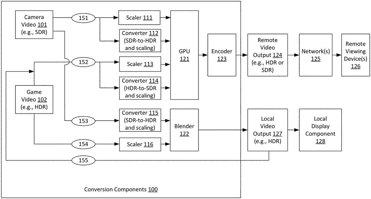
FIG.1is a diagram illustrating an example video conversion system that may be used in accordance with the present disclosure. As shown inFIG.1, conversion components100receive video inputs including game video102and camera (e.g., webcam) video101. The game video102may be received from a video game that renders the game video102. The camera video101may be captured by, and received from, a video camera. The camera video101may include video that shows a game player playing, and commentating on, the video game. In the example ofFIG.1, game video102is received, by the conversion components100, from a video game that provides HDR video. Thus, game video102includes HDR video when the game video102is received by the conversion components100. It is noted, however, that the techniques described herein are not limited to use with HDR video games and that SDR game video may also be employed. Additionally, in the example ofFIG.1, camera video101is received, by the conversion components100, from an SDR camera. Thus, camera video101includes SDR video when the camera video101is received by the conversion components100. It is noted, however, that the techniques described herein are not limited to use with SDR cameras and that HDR cameras may also be employed. In some examples, the conversion components100may receive multiple camera video feeds from multiple different cameras. Moreover, in some examples, the conversion components100may receive one or more camera video feeds from SDR cameras as well as one or more camera video feeds from HDR cameras.
As also shown inFIG.1, conversion components100provide video outputs including local video output127and remote video output124. As shown, local video output127is provided to a local display component128(e.g., television), such as for display to the video game player as he or she plays the video game. Additionally, the remote video output124is transmitted over one or more network(s)125, such as to one or more remote viewing device(s)126(e.g., via a video streaming service). The remote video output124may be transmitted over one or more local area networks (LAN's) and/or one or more wide area networks (WAN's), such as the Internet. Additionally, the remote video output124may be transmitted using streaming transmission techniques, in which portions of transmitted content are received and played while subsequent portions of the transmitted content are being transmitted. In some examples, the remote video output124may be transmitted to, and played by, remote viewing device(s)126using live streaming techniques. The term live streaming, as used herein, refer to scenarios in which video content of an event (e.g., a video game) may be transmitted to viewers, and at least part of the video content may be played while the event is still occurring (e.g., while the video game is still being played by the players), albeit with some small amounts latency between the time that video content is captured and the time that the video is eventually played to viewers.
In the example ofFIG.1, both the local video output127and the remote video output124may optionally include the game video102and the camera video101. Additionally, in the example ofFIG.1, the local video output127includes HDR video, and the local display component128is configured to display HDR video. It is noted, however, that the techniques described herein are not limited to use with HDR local display components and that SDR local display components may also be employed. Furthermore, in the example ofFIG.1, the remote video output124may include either HDR or SDR video. For example, in some cases, the conversion components100may provide one or more user interfaces that may be displayed via local display component128and that may allow a user (e.g., video game player) to select whether the remote video output124is to be streamed as HDR or SDR video. These user interfaces may also allow the user to select a desired image resolution for streaming.
As shown inFIG.1, the game video102, which is received by the conversion components100as HDR video, may be included in the remote video output124via path152. Specifically, via path152, the game video102is provided to either a scaler113or a converter114, depending upon whether HDR streaming or SDR streaming is selected for remote video output124. For scenarios in which SDR streaming is selected, it is necessary to convert the game video102from HDR video (as provided by the video game) to SDR video (for SDR streaming). Thus, when SDR streaming is selected, the game video102is provided, via path152, to converter114, which converts the game video102from HDR video to SDR video. Converter114may also optionally scale the resolution of game video102, if necessary, to match a desired transmission resolution. For example, if the game video102, as provided by the video game, has 4 k resolution, and the user selects 1080p resolution for remote video output124, then the converter114may downscale the game video102from 4 k resolution to 1080p resolution. By contrast, for scenarios in which HDR streaming is selected, it is not necessary to convert the game video102from HDR video to SDR video. Thus, when HDR streaming is selected, the game video102is provided, via path152, to scaler113. Scaler113does not convert the game video102from HDR video to SDR video. However, scaler113may optionally scale the resolution of game video102, if necessary, to match a desired transmission resolution as described above.
Additionally, the game video102may be included in the local video output127via path154. As described above, in the example ofFIG.1, the local display component128is an HDR display. Thus, in the example ofFIG.1, it is not necessary to convert the game video102from HDR video to SDR video. Accordingly, the game video102is provided, via path154, to scaler116. Scaler116does not convert the game video102from HDR video to SDR video. However, scaler116may optionally scale the resolution of game video102, if necessary, to match the display resolution of the local display component128. In some examples, the display resolution of the local display component128, as well as an indication of whether the local display component128supports HDR video, may also be entered, by the user, into one or more user interfaces provided by the conversion components100.
As also shown inFIG.1, the camera video101, which is received by the conversion components100as SDR video, may be included in the remote video output124via path151. Specifically, via path151, the camera video101is provided to either a scaler111or a converter112, depending upon whether HDR streaming or SDR streaming is selected for remote video output124. For scenarios in which HDR streaming is selected, it is necessary to convert the camera video101from SDR video (as provided by an SDR camera) to HDR video (for HDR streaming). Thus, when HDR streaming is selected, the camera video101is provided, via path151, to converter112, which converts the camera video101from SDR video to HDR video. Converter114may also optionally scale the resolution of camera video101, if necessary, to match a desired transmission resolution. By contrast, for scenarios in which SDR streaming is selected, it is not necessary to convert the camera video101from SDR video to HDR video. Thus, when SDR streaming is selected, the camera video101is provided, via path151, to scaler111. Scaler111does not convert the camera video101from SDR video to HDR video. However, scaler111may optionally scale the resolution of camera video101, if necessary, to match a desired transmission resolution.
Additionally, the camera video101may be included in the local video output127via path153. As described above, in the example ofFIG.1, the local display component128is an HDR display. Thus, in the example ofFIG.1, it is necessary to convert the camera video101from SDR video to HDR video. Accordingly, the camera video101is provided, via path153, to converter115. Converter115converts the camera video101from SDR video to HDR video. Additionally, converter115may optionally scale the resolution of camera video101, if necessary, to match the display resolution of the local display component128. It is noted that a person of ordinary skill in the art will appreciate that there are multiple SDR to HDR and HDR to SDR conversion techniques that may be employed by converters112,114and/or115, as applicable.
The conversion components100include a graphics processing unit (GPU)121, which processes the scaled and/or converted camera video101and game video102to generate the remote video output124. Specifically, when SDR streaming is selected, the GPU121receives video from scaler111(which provides camera video101as SDR video) and converter114(which provides game video102as SDR video). The GPU121then combines the video from scaler111and converter114into remote video output124, which is encoded for transmission via encoder123. By contrast, when HDR streaming is selected, the GPU121receives video from converter112(which provides camera video101as HDR video) and scaler113(which provides game video102as HDR video). The GPU121then combines the video from converter112and scaler113into remote video output124, which is encoded for transmission via encoder123.
Additionally, the conversion components100include a blender122, which blends the outputs of converter115and scaler116to generate the local video output127. Specifically, the blender122receives video from converter115(which provides camera video101as HDR video) and scaler116(which provides game video102as HDR video). The blender122then combines the video from converter115and scaler116into local video output127, which is provided to local display component128. It is noted that the conversion components100may include any number of additional or alternative components not shown inFIG.1. For example, for scenarios in which camera video is additionally or alternatively received from an HDR camera, the conversion components100may include one or more additional HDR-to-SDR converters to convert the camera video from HDR to SDR, such as to enable SDR streaming of the camera video to remote viewing device(s)126. Moreover, in some examples, there may be no camera video provided from any cameras, and no camera video may be included in the remote video output124or the local video output127.
Referring now toFIG.2, an example video game streaming system will now be described in detail. As shown inFIG.2, the local display component128is included in a local display device210(e.g., smart television or other television). In the example ofFIG.2, the conversion components100are included in an intermediary device200that is separate from the local display device210. In some examples, the game video102may be received, by the conversion components100, from a game console211, which may execute a video game that renders the game video. In some other examples, the game video102may be server-rendered game video that may be received, by the conversion components100, from a game service212. The game service212may include one or more remote servers, such as cloud-gaming servers, that execute the video game that renders the game video. The camera video101may be provided by a camera that is included in one or more camera(s)213, such as one or more webcams. In some examples, the camera(s)213may include multiple HDR and/or SDR cameras that provide camera video to the conversion components100. In some cases, the intermediary device200may include one or more HDMI™ or other digital video input ports, for example to receive video input from game console211, camera(s)213and/or other devices. Additionally, the intermediary device200may include one or more HDMI™ or other digital video output ports, for example to provide video to local display device210and/or other devices. The intermediary device200may also include one or more wired and/or wireless network connections, such as to send and receive data to and from the Internet and other networks (e.g., to receive game video101from game service212, to send remote video output to remote viewing device(s)126, etc.). In one specific example, the intermediary device200may perform other television-related functionality, such as allowing downloading and executing of applications for watching movies, television programs, playing music, online shopping, and the like. In some examples, the intermediary device200may have a corresponding remote control, such as to allow users to make selections in a user interfaces that are provided by conversion components100and displayed on local display component128. The intermediary device200may be a computing device that includes one or more processors and one or more memories, such as described below with reference toFIG.13.
Referring now toFIG.3, an alternative configuration of a video streaming system will now be described in detail. In the example, ofFIG.3, the conversion components100are integrated into an integrated display device300(e.g., a smart television) that includes the local display component128. In some cases, the integrated display device300may include one or more HDMI™ or other digital video input ports, for example to receive video input from game console211, camera(s)213and/or other devices. The integrated display device300may also include one or more wired and/or wireless network connections, such as to send and receive data to and from the Internet and other networks (e.g., to receive game video102from game service212, to send remote video output to remote viewing device(s)126, etc.). In some examples, the integrated display device300may have a corresponding remote control, such as to allow users to make selections in a user interfaces that are provided by conversion components100and displayed on local display component128. The integrated display device300may be a computing device that includes one or more processors and one or more memories, such as described below with reference toFIG.13.
One or more user interfaces provided by the conversion components100may allow the user to configure the arrangements for the remote video output124and the local video output127. For example, the user interfaces may allow the user to select each video feed that is displayed in each of the remote video output124and in the local video output127as well as the respective size, shape (e.g., aspect ratio), and location of each video feed in each of the remote video output124and in the local video output127. The user interfaces may also allow the user to dynamically (e.g., during gameplay) modify any, or all, of the configurations and selections for the local video output127and the remote video output124. In some examples, the conversion components may include one or more additional GPU's (e.g., in addition to GPU121), such as for rendering of the one or more user interfaces. The output of these additional GPU's may be provided directly, or indirectly, to blender122.
Referring back toFIG.1, it is shown that the conversion components100include GPU121, which allows processing of the remote video output124independently of the local video output127. This may allow the remote video output124to be arranged differently than the local video output127. For example, this may allow the remote video output to include video feeds that are not included in the local video output. Referring now toFIG.4, an example is show in which a given video feed (i.e., camera video101) is included in the remote video output124but not in the local video output127. In particular, in the example ofFIG.4, the remote video output124includes a portal402, which includes game video102. Additionally, the remote video output124also includes a portal403, which includes camera video101. By contrast, the local video output127includes only portal401, which includes the game video102. Thus, in this example, the remote video output124includes both camera video101and game video102, while the local video output127includes only game video102. In some examples, the arrangement ofFIG.4may be advantageous, such as because game players may not wish to view video of themselves in camera video101and would instead prefer to use the local display component128to view game video102. It is noted that one or more features (e.g., resolution, dynamic range, etc.) of the game video102included in portal401may differ from one or more features (e.g., resolution, dynamic range, etc.) of the game video102included in portal402. For example, in some cases, the game video102included in portal401may be HDR video, while the game video102included in portal402may be SDR video (e.g., for scenarios in which the user selects to stream video in SDR). Additionally, the resolution of game video102included in portal401may differ from the resolution of game video102included in portal402.
In some examples, one or more video feeds may occupy a different display area in the remote video output124than in the local video output127. For example, a video feed may have a different size and/or shape (e.g., aspect ratio) in the remote video output124than in the local video output127. As a specific example, the camera video101may sometimes occupy a larger display area in the remote video output124than in the local video output127. As another specific example, the camera video101may sometimes have a square shape in the remote video output124but may have a non-square rectangular shape in the local video output127. As yet another specific example, the camera video101may be located at the bottom-right corner of the remote video output124but may be located at the top-left corner of the local video output127.
The term display area refers to an area of the remote video output124or the local video output127that is occupied by a portal. For example, inFIG.4, the display area of portal402in the remote video output124is the portion of the remote video output124that is occupied by portal402(i.e., the upper left portion of remote video output124). By contrast, the display area of portal401in the local video output127is the portion of the remote video output124that is occupied by portal402(i.e., the upper left portion of remote video output124). It is noted that both portals401and402include the same video feed (i.e., game video102), albeit with potentially different dynamic ranges, resolutions, etc. Thus, in the example ofFIG.4, the game video102occupies a different display area in the remote video output124than in the local video output127(i.e., because portals401and402have different sizes, different shapes and occupy different respective locations of local video output127and remote video output124). Generally, a video feed may occupy a different display area in the remote video output124than in the local video output127if the portals that include the video feed have a different size as one another, a different shape as one another, and/or different respective locations in the remote video output124and the local video output127. By contrast, a video feed may occupy a same display area in the remote video output124and the local video output127if the portals that include the video feed have the same size as one another, the same shape as one another, and the same respective locations in the remote video output124and the local video output127.
Referring now toFIG.5, an example is shown in which both the camera video101and the game video102occupy different display areas in the remote video output124than in the local video output127. In particular, in the example ofFIG.5, the remote video output124includes portal402, which includes game video102. Additionally, the local video output127includes portal502, which also includes game video102. However, the location of portal402in remote video output124differs from the location of portal502in local video output127. Specifically, portal402occupies the top-left portion of remote video output124. By contrast, portal502occupies all of local video output127with the exception of the portion overlayed by portal501. Additionally, portal502is larger than portal402. Furthermore, portal502has a different shape (e.g., different aspect ratio) than portal402. As also shown inFIG.5, the remote video output124includes portal403, which includes camera video101. Additionally, the local video output127includes portal501, which also includes camera video101. However, the location of portal403in remote video output124differs from the location of portal501in local video output127. Specifically, portal403occupies the bottom-right portion of remote video output124. By contrast, portal501occupies the middle-left portion of local video output127. Additionally, portal403is larger than portal501. Furthermore, portal403has a different shape (e.g., different aspect ratio) than portal501.
In some examples, the local video output127may include video feeds that are not included in the remote video output124. For example, in some cases, an additional video input, such as a chat interface that displays chat messages associated with the video game, may be included in the local video output127but not in the remote video output124. Referring now toFIG.6, an example is shown in which the local video output127includes an additional video input that is not included in the remote video output124. In particular, in the example ofFIG.6, the remote video output124again includes a portal402, which includes game video102, and portal403, which includes camera video101. By contrast, the local video output127includes portals601and602. Portal601includes the game video102. Additionally, portal602includes chat or other data received, by the conversion components100, from game service212. In one specific example, portal602may be a chat interface that displays chat messages associated with the video game that renders game video102. Additionally, in some examples, the conversion components100may include one or more additional GPU's (e.g., in addition to GPU121), such as for rendering of a chat interface (or other interface) that may be displayed in portal602. The output of these additional GPU's may be provided directly, or indirectly, to blender122.
Thus,FIGS.4-6depict some example scenarios in which the remote video output124may have a different arrangement than the local video output127. In some other examples, however, it may be advantageous for the remote video output124to have the same arrangement as the local video output127. In these scenarios, the conversion components100may provide the local video output127as an input that is used to generate the remote video output124, thereby causing the remote video output124to have the same arrangement as the local video output127(albeit with potentially different dynamic range, resolution, etc.). Referring back toFIG.1, it is shown that, for scenarios in which the remote video output124has the same arrangement as the local video output127, the local video output127may be split and provided to both the local display component128and to an additional path155. The local video output127may then be provided, via path155, as an input to path152. This means that, via path152, the local video output127may be provided to either scaler113or converter114, depending upon whether HDR streaming or SDR streaming is selected for remote video output124. For scenarios in which SDR streaming is selected, it is necessary to convert the local video output127from HDR video to SDR video (for SDR streaming). Thus, when SDR streaming is selected, the local video output is provided, via path152, to converter114, which converts the local video output127from HDR video to SDR video. Converter114may also optionally scale the resolution of the local video output127, if necessary, to match a desired transmission resolution. By contrast, for scenarios in which HDR streaming is selected, it is not necessary to convert the local video output127from HDR video to SDR video. Thus, when HDR streaming is selected, the local video output127is provided, via path152, to scaler113. Scaler113does not convert the local video output127from HDR video to SDR video. However, scaler113may optionally scale the resolution of the local video output127, if necessary, to match a desired transmission resolution as described above. In this manner, the local video output127may be used to generate the remote video output124, thereby causing the remote video output124to have the same arrangement as the local video output127.
Furthermore, in some examples, when the remote video output124and the local video output127have different arrangements (e.g., as shown inFIGS.4-6), the conversion components100may allow the remote video output124to be temporarily connected to the local display component128, thereby allowing the user to temporarily view, on the local display component128, the same output that is being seen by remote viewers. This may be helpful, such as to allow the user to temporarily see what his or her viewers are seeing. For example, the user may wish to confirm that the webcam feed in the remote video output is not blocking or certain portions of the game video. Thus, the conversion components may allow the user to switch the input to the local display between the local video output and the remote video output. Referring now toFIG.7, an example is shown in which the video that is provided, by the conversion components100, to the local display component128is switched between the local video output127and the remote video output124. In particular, in the left portion ofFIG.7, it is shown that, at time T=1, the local video output127is provided to the local display component128. In this example, the local video output127includes portal601(including game video102) and portal602(including chat or other data from game service212). As shown in the middle portion ofFIG.7, at time T=2 (which is a later time subsequent to time T=1), the video that is provided to the local display component128is switched from the local video output127to the remote video output124. In this example, the remote video output124includes portal402(including game video102) and portal403(including camera video101). As shown in the right portion ofFIG.7, at time T=3 (which is a later time subsequent to time T=2), the video that is provided to the local display component128is switched back from the remote video output124to the local video output127. In some examples, switching of the video that is provided to the local display component128between the local video output127and the remote video output124may be performed based one or more user commands. The conversion components100may optionally include a switching component, such as to perform switching between the local video output127and the remote video output124. Both the local video output127and the remote video output124may be connected to the switching component, while the output of the switching component may be provided to the local display component128.
The conversion components100may allow the user to switch the remote video output124(and/or the local video output127) between different cameras. In one specific example, for most of the game transmission, the player may transmit video from a side-view camera that is zoomed-out to show not only the player's face but also the player's body, such as to show hand gestures and other player actions. However, at certain times during gameplay, such as right after key events (e.g., winning a battle, scoring a touchdown, etc.), the player may wish to temporarily transmit video from a front-view camera that is zoomed-in on the player's face, such as to show facial expressions in response to these key game events. The conversion components may allow the game player to switch between these multiple cameras with different camera angles, zoom levels, etc.
Referring now toFIG.8, an example is shown in which the remote video output124is switched between a side view camera video812and a front view camera video811. As shown at the top ofFIG.8, conversion components100may receive side view camera video812from side view camera802. Conversion components100may also receive front view camera video811from front view camera801. Side view camera802may be zoomed-out to show not only the player's face but also the player's body, such as to show hand gestures and other player actions. By contrast, front view camera801that may be zoomed-in on the player's face. As also shown inFIG.8, at time T=1, remote video output includes portals402and821. Portal402includes game video102, while portal821includes side view camera video812. Subsequently, at time T=2 (which is a later time subsequent to T=1), the remote video output is switched to have portal822replace portal821. As shown, portal822includes front view camera video811as opposed to side view camera video812. For example, time T=2 may occur right after a key video game event (e.g., winning a battle, scoring a touchdown, etc.), and the player may wish to temporarily transmit front view camera video811that is zoomed-in on the player's face, such as to show facial expressions in response to these key game events. Subsequently, at time T=3 (which is a later time subsequent to T=2), the remote video output is switched back to have portal821(which includes side view camera video812) replace portal822(which includes front view camera video811).
FIG.9is a flowchart illustrating an example video game streaming process with local HDR output and remote HDR output that may be used in accordance with the present disclosure. In some examples, the process ofFIG.9may be performed by the conversion components100(and, therefore, by a computing device that may include the conversion components100, such as intermediary device200ofFIG.2or integrated display device300ofFIG.3). Thus, in some examples, a computing device that performs the process ofFIG.9may include the local display component or may be external to a display device that includes the local display component. As shown, the process ofFIG.9is initiated at operation910, at which instructions are received to perform HDR video transmission to remote devices. As described above, the conversion components100may allow either HDR or SDR video transmission to remote viewing device(s)126. In some examples, the conversion components100may provide one or more user interfaces, which may be displayed via the local display component128. The user interfaces provided by the conversion component may allow and/or assist the user in selecting (e.g., via a remote control of the intermediary device200ofFIG.2and/or the integrated display device300ofFIG.3) either HDR or SDR video transmission to remote viewing device(s)126. User selections may also be received through other inputs, e.g., voice command, etc. Thus, operation910may include receiving a user selection to perform HDR video transmission to remote devices.
At operation912, settings, including portal arrangement, are received for the remote video output. In some examples, one or more of these settings may be selected by, and received from, a user, such as via one or more user interfaces that may be provided by the conversion components100and displayed on the local display component128(including via a remote control of the intermediary device200ofFIG.2and/or the integrated display device300ofFIG.3that makes selections in the user interface). The settings received at operation912include portal arrangement, such as the display area (e.g., size, shape, and location) of each portal within the remote video output. For example, indications may be provided of which video feeds are to be included in the remote video output, such as game video, camera video, and/or additional video feeds (e.g., chat interface, etc.). In some examples, each of the selected video feeds may have a respective portal that is included in the remote video output. In one specific example, a conversion component user interface may show an area that represents the remote video output and that includes a graphical representation of each portal in the remote video output. Each portal graphical representation may have sides that can be adjusted, such by dragging and dropping a side. This may allow re-sizing and re-shaping of the portals. Additionally, each portal graphical representation may be moved to a desired location in the area, such by dragging and dropping the portal graphical representation. This may allow the user to select the respective location of the portal within the remote video output. In this manner, the user interface may allow the user to select a respective display area (e.g., size, shape, and location) for each portal in the remote video output. Thus, in these and other examples, at least one user interface may be provided that allows a user to define a visual arrangement of one or more portals included in the remote video output. The settings received at operation912may also include a desired image resolution for the remote video output.
At operation914, settings, including portal arrangement, are received for the local video output. In some examples, one or more of these settings may be selected by, and received from, a user, such as via one or more user interfaces that may be provided by the conversion components100and displayed on the local display component128(including via a remote control of the intermediary device200ofFIG.2and/or the integrated display device300ofFIG.3that makes selections in the user interface). The settings received at operation914include portal arrangement, such as the display area (e.g., size, shape, and location) of each portal within the remote video output. For example, indications may be provided of which video feeds are to be included in the local video output, such as game video, camera video, and/or additional video feeds (e.g., chat interface, etc.). In some examples, each of the selected video feeds may have a respective portal that is included in the local video output. In one specific example, a conversion component user interface may show an area that represents the local video output and the includes a graphical representation of each portal in the local video output. Each portal graphical representation may have sides that can be adjusted, such by dragging and dropping a side. This may allow re-sizing and re-shaping of the portals. Additionally, each portal graphical representation may be moved to a desired location in the area, such by dragging and dropping the portal graphical representation. This may allow the user to select the respective location of the portal within the local video output. In this manner, the user interface may allow the user to select a respective display area (e.g., size, shape, and location) for each portal in the remote video output. Thus, in these and other examples, at least one user interface may be provided that allows a user to define a visual arrangement of one or more portals included in the local video output. The settings received at operation912may also include a resolution of the local display component (which may be used as the image resolution for the local video output) as well as an indication to provide the local video output using HDR video.
At operation916, first video input is received including first HDR video content. The first video input may be game video that is received from, and rendered by, a video game. Thus, the first HDR video content may be game video. For example, as shown inFIG.1, game video102is received by the conversion components100. The game video102may include HDR video upon being received by the conversion components100from the video game. At operation918, second video input is received including SDR video content. The second video input may be camera video that is received from, and captured by, a camera. Thus, the SDR video content may be camera video. For example, as shown inFIG.1, camera video101is received by the conversion components100. The camera video101may include SDR video upon being received by the conversion components100from the camera.
At operation920, the SDR video content is converted to second HDR video content. For example, as shown inFIG.1, the camera video101may be provided, via path151, to a converter115, which converts the camera video101from SDR video to HDR video (and optionally scales the camera video101) for transmission to remote viewing device(s)126via remote video output124. As also shown inFIG.1, the camera video101may be provided, via path153, to converter115, which converts the camera video101from SDR video to HDR video (and optionally scales the camera video101) for display on the local display component128via local video output127. Thus, in this example, operation920may include optionally either, or both, of the conversions of camera video101performed by converter112and/or by converter115. Moreover, in this example, optionally either, or both, of the outputs of converter112and/or converter115may be considered to be second HDR video content, for example in the sense that providing video including either of those outputs may be considered to be providing video that includes the second HDR video content.
At operation922, remote video output including the first HDR video content and the second HDR video content is provided, wherein the remote video output is transmitted over one or more networks. For example, as shown inFIG.1, the conversion components100may provide remote video output124. For scenarios in which HDR streaming is selected for the remote video output124, the GPU121may combine the outputs of converter112and scaler113into the remote video output124. Specifically, the first HDR video content may be included in the remote video output124via the output of scaler113(including game video102as HDR video optionally scaled for remote transmission). Additionally, the second HDR video content may be included in the remote video output124via the output of converter112(including the camera video101converted from SDR to HDR and optionally scaled for remote transmission).
At operation924, local video output including the first HDR video content is provided, wherein the local video output is displayed on a local display component. For example, as shown inFIG.1, the conversion components100may provide local video output127. Specifically, the first HDR video content may be included in the local video output127via the output of scaler116(including game video102as HDR video optionally scaled for local display). Additionally, in some examples, the local video output127may sometimes optionally further include the second HDR video content, which may be included in the local video output127via the output of converter115(including the camera video101converted from SDR to HDR and optionally scaled for local display). As shown in the examples ofFIGS.4-6, the size, shape and/or location of the first HDR video (e.g., the game video102) may be different in the remote video output than in the local video output. Additionally, the size, shape and/or location of the second HDR video (e.g., the camera video101converted from SDR to HDR) may be different in the remote video output than in the local video output.
FIG.10is a flowchart illustrating an example video game streaming process with local HDR output and remote SDR output that may be used in accordance with the present disclosure. In some examples, the process ofFIG.10may be performed by the conversion components100(and, therefore, by a computing device that may include the conversion components100, such as intermediary device200ofFIG.2or integrated display device300ofFIG.3). Thus, in some examples, a computing device that performs the process ofFIG.10may include the local display component or may be external to a display device that includes the local display component. As shown, the process ofFIG.10is initiated at operation1010, at which instructions are received to perform SDR video transmission to remote devices. As described above, the conversion components100may allow either HDR or SDR video transmission to remote viewing device(s)126. In some examples, the conversion components100may provide one or more user interfaces, which may be displayed via the local display component128. The user interfaces provided by the conversion component may allow and/or assist the user in selecting (e.g., via a remote control of the intermediary device200ofFIG.2and/or the integrated display device300ofFIG.3) either HDR or SDR video transmission to remote viewing device(s)126. User selections may also be received through other inputs, e.g., voice command, etc. Thus, operation1010may include receiving a user selection to perform SDR video transmission to remote devices.
At operation1012, settings, including portal arrangement, are received for the remote video output. Operation1012may be the same as operation912ofFIG.9, and the description of operation912is therefore considered to apply to operation1012(without being repeated here). At operation914, settings, including portal arrangement, are received for the local video output. Operation1014may be the same as operation914ofFIG.9, and the description of operation914is therefore considered to apply to operation1014(without being repeated here). At operation1016, first video input is received including first HDR video content. Operation1016may be the same as operation916ofFIG.9, and the description of operation916is therefore considered to apply to operation1016(without being repeated here). At operation1018, second video input is received including first SDR video content. Operation1018may be the same as operation918ofFIG.9, and the description of operation918is therefore considered to apply to operation1018(without being repeated here).
At operation1020, the first HDR video content is converted to second SDR video content. For example, as shown inFIG.1, the game video102may be provided, via path152, to a converter114, which converts the game video102from HDR video to SDR video (and optionally scales the game video102) for transmission to remote viewing device(s)126via remote video output124.
At operation1022, the first SDR video content is converted to second HDR video content. For example, as shown inFIG.1, the camera video101may be provided, via path153, to converter115, which converts the camera video101from SDR video to HDR video (and optionally scales the camera video101) for display on the local display component128via local video output127.
At operation1024, remote video output including the first SDR video content and the second SDR video content is provided, wherein the remote video output is transmitted over one or more networks. For example, as shown inFIG.1, the conversion components100may provide remote video output124. For scenarios in which SDR streaming is selected for the remote video output124, the GPU121may combine the outputs of scaler111and converter114into the remote video output124. Specifically, the first SDR video content may be included in the remote video output124via the output of scaler111(including camera video101as SDR video optionally scaled for remote transmission). Additionally, the second SDR video content may be included in the remote video output124via the output of converter114(including the game video102converted from HDR to SDR and optionally scaled for remote transmission).
At operation1026, local video output including the first HDR video content provided, wherein the local video output is displayed on a local display component. For example, as shown inFIG.1, the conversion components100may provide local video output127. Specifically, the first HDR video content may be included in the local video output127via the output of scaler116(including game video102as HDR video optionally scaled for local display). Additionally, in some examples, the local video output127may sometimes optionally further include the second HDR video content, which may be included in the local video output127via the output of converter115(including the camera video101converted from SDR to HDR and optionally scaled for local display).
FIG.11is a flowchart illustrating an example video game streaming process with local and remote outputs having different respective portal arrangements that may be used in accordance with the present disclosure. In some examples, the process ofFIG.11may be performed by the conversion components100(and, therefore, by a computing device that may include the conversion components100, such as intermediary device200ofFIG.2or integrated display device300ofFIG.3). Thus, in some examples, a computing device that performs the process ofFIG.11may include the local display component or may be external to a display device that includes the local display component. As shown, the process ofFIG.11is initiated at operation1110, at which settings, including portal arrangement, are received for the remote video output. Operation1110may be the same as operation912ofFIG.9, and the description of operation912is therefore considered to apply to operation1110(without being repeated here). At operation1112, settings, including portal arrangement, are received for the local video output. Operation1112may be the same as operation914ofFIG.9, and the description of operation914is therefore considered to apply to operation1112(without being repeated here).
At operation1114, a first video input including a first video feed is received. The first video feed may be received from, and rendered by, a video game. Thus, the first video feed may be a game video feed. For example, as shown inFIG.1, game video102is received by the conversion components100. At operation1116, second video input is received including a second video feed. The second video feed may be received from, and captured by, a camera. Thus, the second video feed may be a camera video feed. For example, as shown inFIG.1, camera video101is received by the conversion components100. It is noted that the term video feed, as used herein, refers to video irrespective of modifiable features such as dynamic range, resolution, etc. Thus, for example, a game video feed may that is converted from HDR to SDR is still considered to be the same video feed both before and after its HDR to SDR conversion. As another example, a camera video feed may that is converted from SDR to HDR is still considered to be the same video feed both before and after its SDR to HDR conversion.
At operation1116, the remote video output comprising first visual portals including the first video feed and the second video feed is provided, wherein the remote video output is transmitted over one or more networks, and wherein the remote video output has a first visual arrangement of the first visual portals. For example, as shown inFIG.1, the remote video output124is provided by the conversion components100for transmission over network(s)125to remote viewing device(s)126. As described above, at least one user interface may be provided that allows a user to define the first visual arrangement (i.e., the portal arrangement for the remote video output) and/or a second visual arrangement (i.e., the portal arrangement for the local video output). For example, operation916describes some examples of how portal arrangement may be defined, such as by a user, for the remote video output, such as by selecting a size, shape (e.g., aspect ratio) and/or location of each portal included in the remote video output. This description is not repeated here.
At operation1118, local video output comprising one or more second visual portals including the first video feed is provided, wherein the local video output is displayed on a local display component, wherein the local video output has a second visual arrangement of the one or more second visual portals, and wherein the second visual arrangement is at least partially different from the first visual arrangement. For example, as shown inFIG.1, the local video output127is provided by the conversion components100to local display component128. As described above, at least one user interface may be provided that allows a user to define the first visual arrangement (i.e., the portal arrangement for the remote video output) and/or the second visual arrangement (i.e., the portal arrangement for the local video output). For example, operation918describes some examples of how portal arrangement may be defined, such as by a user, for the local video output, such as by selecting a size, shape (e.g., aspect ratio) and/or location of each portal included in the remote video output. This description is not repeated here. It is noted that the second video feed may also sometimes be optionally included in the one or more second visual portals.
It is noted thatFIGS.4-6show some examples in which the first visual arrangement is at least partially different from the second visual arrangement. In some examples, the second visual arrangement may differ from the first visual arrangement at least because the second video feed is not included in the one or more second visual portals. For example, as shown inFIG.4, the remote video output124includes portal402(including game video102) and portal403(including camera video101). By contrast, the local video output127includes only portal401(including game video102) and no portal including camera video101.
Additionally, in some examples, the second visual arrangement may differ from the first visual arrangement at least because the first video feed occupies at least a partially different display area in the second visual arrangement than in the first visual arrangement. This means that the first video feed has a different size, different shape (e.g., aspect ratio) and/or occupies at least partially different respective locations of the remote video output124and the local video output127.FIG.5illustrates an example in which all three of these conditions (e.g., different size, different shape, and at least partially different respective locations of the remote video output124and the local video output127) are met. For example, as shown inFIG.5, portal402(which includes game video102) and portal502(which includes game video102) occupy at least partially different respective locations of remote video output124and local video output127. Specifically, portal402occupies the top-left portion of remote video output124. By contrast, portal502occupies all of local video output127with the exception of the portion overlayed by portal501. Additionally, portal502is larger than portal402. Furthermore, portal502has a different shape (e.g., different aspect ratio) than portal402.
Furthermore, in some examples, the second visual arrangement may differ from the first visual arrangement at least because the one or more second visual portals may include a third video feed that is not included in the first visual portals. For example, as shown inFIG.6, the local video output127includes portal601(including game video102) and portal602, which includes an additional video feed (i.e., chat or other data from game service212). By contrast, inFIG.6, the remote video output124does not include a portal that includes chat or other data from game service212. Rather, remote video output instead includes portal402(including game video102) and portal403(including camera video101).
At operation1122, input to the local display component is optionally switched between the remote video output and the local video output. For example, as shown inFIG.7, input to the local display component128may be switched between the remote video output124and the local video output127. This may allow the user to temporarily view, on the local display, the same output that is being seen by remote viewers. This may be helpful, such as to allow the user to temporarily see what his or her viewers are seeing. For example, the user may wish to confirm that the webcam feed in the remote video output is not blocking certain portions of the game video. It is, therefore, noted that the feature that the local video output is displayed on a local display component, for example as specified in operations1120,1026and924, does not require that the local video output must be displayed on the local display component for an entire duration of the local video output (e.g., an entire duration that a game is being played). Rather, the local video output need only be displayed on the local display component for at least some viewable time period in order to satisfy this feature, for example such as to allow switching of the input to the local display component between the local video output and the remote video output.
As described above, in some examples, the second video feed may be received from a first camera. For example, referring back toFIG.8, the second video feed may be side view camera video812received from side view camera802. In some examples, the remote video output may be switched between the second video feed and an additional video feed received from an additional camera. For example, as show inFIG.8, the remote video output124may be switched between side view camera video812and front view camera video811(received from front view camera801). This may allow a view to be temporarily switched to the additional view feed, such as to quickly show a player's reaction to a key game event. It is, therefore, noted that the feature that the remote video output comprises first visual portals including the first video feed and the second video feed, for example as specified in operation1118, does not require that a visual portal including the second feed must be included in the remote video output for an entire duration of the remote video output (e.g., an entire duration that game video is being transmitted to remote viewers). Rather, a visual portal including the second feed need only be included in the remote video output for at least some viewable time period in order to satisfy this feature, for example such as to allow switching of the remote video output between the second video feed and an additional video feed received from an additional camera.
An example system for transmitting and providing data will now be described in detail. In particular,FIG.12illustrates an example computing environment in which the embodiments described herein may be implemented.FIG.12is a diagram schematically illustrating an example of a data center85that can provide computing resources to users70aand70b(which may be referred herein singularly as user70or in the plural as users70) via user computers72aand72b(which may be referred herein singularly as computer72or in the plural as computers72) via a communications network73. Data center85may be configured to provide computing resources for executing applications on a permanent or an as-needed basis. The computing resources provided by data center85may include various types of resources, such as gateway resources, load balancing resources, routing resources, networking resources, computing resources, volatile and non-volatile memory resources, content delivery resources, data processing resources, data storage resources, data communication resources and the like. Each type of computing resource may be available in a number of specific configurations. For example, data processing resources may be available as virtual machine instances that may be configured to provide various web services. In addition, combinations of resources may be made available via a network and may be configured as one or more web services. The instances may be configured to execute applications, including web services, such as application services, media services, database services, processing services, gateway services, storage services, routing services, security services, encryption services, load balancing services, application services and the like. These services may be configurable with set or custom applications and may be configurable in size, execution, cost, latency, type, duration, accessibility and in any other dimension. These web services may be configured as available infrastructure for one or more clients and can include one or more applications configured as a platform or as software for one or more clients. These web services may be made available via one or more communications protocols. These communications protocols may include, for example, hypertext transfer protocol (HTTP) or non-HTTP protocols. These communications protocols may also include, for example, more reliable transport layer protocols, such as transmission control protocol (TCP), and less reliable transport layer protocols, such as user datagram protocol (UDP). Data storage resources may include file storage devices, block storage devices and the like.
Each type or configuration of computing resource may be available in different sizes, such as large resources—consisting of many processors, large amounts of memory and/or large storage capacity—and small resources—consisting of fewer processors, smaller amounts of memory and/or smaller storage capacity. Customers may choose to allocate a number of small processing resources as web servers and/or one large processing resource as a database server, for example.
Data center85may include servers76aand76b(which may be referred herein singularly as server76or in the plural as servers76) that provide computing resources. These resources may be available as bare metal resources or as virtual machine instances78a-d(which may be referred herein singularly as virtual machine instance78or in the plural as virtual machine instances78).
The availability of virtualization technologies for computing hardware has afforded benefits for providing large scale computing resources for customers and allowing computing resources to be efficiently and securely shared between multiple customers. For example, virtualization technologies may allow a physical computing device to be shared among multiple users by providing each user with one or more virtual machine instances hosted by the physical computing device. A virtual machine instance may be a software emulation of a particular physical computing system that acts as a distinct logical computing system. Such a virtual machine instance provides isolation among multiple operating systems sharing a given physical computing resource. Furthermore, some virtualization technologies may provide virtual resources that span one or more physical resources, such as a single virtual machine instance with multiple virtual processors that span multiple distinct physical computing systems.
Referring toFIG.12, communications network73may, for example, be a publicly accessible network of linked networks and possibly operated by various distinct parties, such as the Internet. In other embodiments, communications network73may be a private network, such as a corporate or university network that is wholly or partially inaccessible to non-privileged users. In still other embodiments, communications network73may include one or more private networks with access to and/or from the Internet.
Communication network73may provide access to computers72. User computers72may be computers utilized by users70or other customers of data center85. For instance, user computer72aor72bmay be a server, a desktop or laptop personal computer, a tablet computer, a wireless telephone, a personal digital assistant (PDA), an e-book reader, a game console, a set-top box or any other computing device capable of accessing data center85. User computer72aor72bmay connect directly to the Internet (e.g., via a cable modem or a Digital Subscriber Line (DSL)). Although only two user computers72aand72bare depicted, it should be appreciated that there may be multiple user computers.
User computers72may also be utilized to configure aspects of the computing resources provided by data center85. In this regard, data center85might provide a gateway or web interface through which aspects of its operation may be configured through the use of a web browser application program executing on user computer72. Alternately, a stand-alone application program executing on user computer72might access an application programming interface (API) exposed by data center85for performing the configuration operations. Other mechanisms for configuring the operation of various web services available at data center85might also be utilized.
Servers76shown inFIG.12may be servers configured appropriately for providing the computing resources described above and may provide computing resources for executing one or more web services and/or applications. In one embodiment, the computing resources may be virtual machine instances78. In the example of virtual machine instances, each of the servers76may be configured to execute an instance manager80aor80b(which may be referred herein singularly as instance manager80or in the plural as instance managers80) capable of executing the virtual machine instances78. The instance managers80may be a virtual machine monitor (VMM) or another type of program configured to enable the execution of virtual machine instances78on server76, for example. As discussed above, each of the virtual machine instances78may be configured to execute all or a portion of an application.
It should be appreciated that although the embodiments disclosed above discuss the context of virtual machine instances, other types of implementations can be utilized with the concepts and technologies disclosed herein. For example, the embodiments disclosed herein might also be utilized with computing systems that do not utilize virtual machine instances.
In the example data center85shown inFIG.12, a router71may be utilized to interconnect the servers76aand76b. Router71may also be connected to gateway74, which is connected to communications network73. Router71may be connected to one or more load balancers, and alone or in combination may manage communications within networks in data center85, for example, by forwarding packets or other data communications as appropriate based on characteristics of such communications (e.g., header information including source and/or destination addresses, protocol identifiers, size, processing requirements, etc.) and/or the characteristics of the private network (e.g., routes based on network topology, etc.). It will be appreciated that, for the sake of simplicity, various aspects of the computing systems and other devices of this example are illustrated without showing certain conventional details. Additional computing systems and other devices may be interconnected in other embodiments and may be interconnected in different ways.
In the example data center85shown inFIG.12, a server manager75is also employed to at least in part direct various communications to, from and/or between servers76aand76b. WhileFIG.12depicts router71positioned between gateway74and server manager75, this is merely an exemplary configuration. In some cases, for example, server manager75may be positioned between gateway74and router71. Server manager75may, in some cases, examine portions of incoming communications from user computers72to determine one or more appropriate servers76to receive and/or process the incoming communications. Server manager75may determine appropriate servers to receive and/or process the incoming communications based on factors such as an identity, location or other attributes associated with user computers72, a nature of a task with which the communications are associated, a priority of a task with which the communications are associated, a duration of a task with which the communications are associated, a size and/or estimated resource usage of a task with which the communications are associated and many other factors. Server manager75may, for example, collect or otherwise have access to state information and other information associated with various tasks in order to, for example, assist in managing communications and other operations associated with such tasks.
It should be appreciated that the network topology illustrated inFIG.12has been greatly simplified and that many more networks and networking devices may be utilized to interconnect the various computing systems disclosed herein. These network topologies and devices should be apparent to those skilled in the art.
It should also be appreciated that data center85described inFIG.12is merely illustrative and that other implementations might be utilized. It should also be appreciated that a server, gateway or other computing device may comprise any combination of hardware or software that can interact and perform the described types of functionality, including without limitation: desktop or other computers, database servers, network storage devices and other network devices, PDAs, tablets, cellphones, wireless phones, pagers, electronic organizers, Internet appliances, television-based systems (e.g., using set top boxes and/or personal/digital video recorders) and various other consumer products that include appropriate communication capabilities.
In at least some embodiments, a server that implements a portion or all of one or more of the technologies described herein may include a computer system that includes or is configured to access one or more computer-accessible media.FIG.13depicts a computer system that includes or is configured to access one or more computer-accessible media. In the illustrated embodiment, computing device15includes one or more processors10a,10band/or10n(which may be referred herein singularly as “a processor10” or in the plural as “the processors10”) coupled to a system memory20via an input/output (I/O) interface30. Computing device15further includes a network interface40coupled to I/O interface30.
In various embodiments, computing device15may be a uniprocessor system including one processor10or a multiprocessor system including several processors10(e.g., two, four, eight or another suitable number). Processors10may be any suitable processors capable of executing instructions. For example, in various embodiments, processors10may be embedded processors implementing any of a variety of instruction set architectures (ISAs), such as the x86, PowerPC, SPARC or MIPS ISAs or any other suitable ISA. In multiprocessor systems, each of processors10may commonly, but not necessarily, implement the same ISA.
System memory20may be configured to store instructions and data accessible by processor(s)10. In various embodiments, system memory20may be implemented using any suitable memory technology, such as static random access memory (SRAM), synchronous dynamic RAM (SDRAM), nonvolatile/Flash®-type memory or any other type of memory. In the illustrated embodiment, program instructions and data implementing one or more desired functions, such as those methods, techniques and data described above, are shown stored within system memory20as code25and data26.
In one embodiment, I/O interface30may be configured to coordinate I/O traffic between processor10, system memory20and any peripherals in the device, including network interface40or other peripheral interfaces. In some embodiments, I/O interface30may perform any necessary protocol, timing or other data transformations to convert data signals from one component (e.g., system memory20) into a format suitable for use by another component (e.g., processor10). In some embodiments, I/O interface30may include support for devices attached through various types of peripheral buses, such as a variant of the Peripheral Component Interconnect (PCI) bus standard or the Universal Serial Bus (USB) standard, for example. In some embodiments, the function of I/O interface30may be split into two or more separate components, such as a north bridge and a south bridge, for example. Also, in some embodiments some or all of the functionality of I/O interface30, such as an interface to system memory20, may be incorporated directly into processor10.
Network interface40may be configured to allow data to be exchanged between computing device15and other device or devices60attached to a network or networks50, such as other computer systems or devices, for example. In various embodiments, network interface40may support communication via any suitable wired or wireless general data networks, such as types of Ethernet networks, for example. Additionally, network interface40may support communication via telecommunications/telephony networks, such as analog voice networks or digital fiber communications networks, via storage area networks such as Fibre Channel SANs (storage area networks) or via any other suitable type of network and/or protocol.
In some embodiments, system memory20may be one embodiment of a computer-accessible medium configured to store program instructions and data as described above for implementing embodiments of the corresponding methods and apparatus. However, in other embodiments, program instructions and/or data may be received, sent or stored upon different types of computer-accessible media. Generally speaking, a computer-accessible medium may include non-transitory storage media or memory media, such as magnetic or optical media—e.g., disk or DVD/CD coupled to computing device15via I/O interface30. A non-transitory computer-accessible storage medium may also include any volatile or non-volatile media, such as RAM (e.g., SDRAM, DDR SDRAM, RDRAM, SRAM, etc.), ROM (read only memory) etc., that may be included in some embodiments of computing device15as system memory20or another type of memory. Further, a computer-accessible medium may include transmission media or signals such as electrical, electromagnetic or digital signals conveyed via a communication medium, such as a network and/or a wireless link, such as those that may be implemented via network interface40.
A network set up by an entity, such as a company or a public sector organization, to provide one or more web services (such as various types of cloud-based computing or storage) accessible via the Internet and/or other networks to a distributed set of clients may be termed a provider network. Such a provider network may include numerous data centers hosting various resource pools, such as collections of physical and/or virtualized computer servers, storage devices, networking equipment and the like, needed to implement and distribute the infrastructure and web services offered by the provider network. The resources may in some embodiments be offered to clients in various units related to the web service, such as an amount of storage capacity for storage, processing capability for processing, as instances, as sets of related services and the like. A virtual computing instance may, for example, comprise one or more servers with a specified computational capacity (which may be specified by indicating the type and number of CPUs, the main memory size and so on) and a specified software stack (e.g., a particular version of an operating system, which may in turn run on top of a hypervisor).
A compute node, which may be referred to also as a computing node, may be implemented on a wide variety of computing environments, such as commodity-hardware computers, virtual machines, web services, computing clusters and computing appliances. Any of these computing devices or environments may, for convenience, be described as compute nodes.
A number of different types of computing devices may be used singly or in combination to implement the resources of the provider network in different embodiments, for example computer servers, storage devices, network devices and the like. In some embodiments a client or user may be provided direct access to a resource instance, e.g., by giving a user an administrator login and password. In other embodiments the provider network operator may allow clients to specify execution requirements for specified client applications and schedule execution of the applications on behalf of the client on execution platforms (such as application server instances, Java′ virtual machines (JVMs), general-purpose or special-purpose operating systems, platforms that support various interpreted or compiled programming languages such as Ruby, Perl, Python, C, C++ and the like or high-performance computing platforms) suitable for the applications, without, for example, requiring the client to access an instance or an execution platform directly. A given execution platform may utilize one or more resource instances in some implementations; in other implementations, multiple execution platforms may be mapped to a single resource instance.
In many environments, operators of provider networks that implement different types of virtualized computing, storage and/or other network-accessible functionality may allow customers to reserve or purchase access to resources in various resource acquisition modes. The computing resource provider may provide facilities for customers to select and launch the desired computing resources, deploy application components to the computing resources and maintain an application executing in the environment. In addition, the computing resource provider may provide further facilities for the customer to quickly and easily scale up or scale down the numbers and types of resources allocated to the application, either manually or through automatic scaling, as demand for or capacity requirements of the application change. The computing resources provided by the computing resource provider may be made available in discrete units, which may be referred to as instances. An instance may represent a physical server hardware platform, a virtual machine instance executing on a server or some combination of the two. Various types and configurations of instances may be made available, including different sizes of resources executing different operating systems (OS) and/or hypervisors, and with various installed software applications, runtimes and the like. Instances may further be available in specific availability zones, representing a logical region, a fault tolerant region, a data center or other geographic location of the underlying computing hardware, for example. Instances may be copied within an availability zone or across availability zones to improve the redundancy of the instance, and instances may be migrated within a particular availability zone or across availability zones. As one example, the latency for client communications with a particular server in an availability zone may be less than the latency for client communications with a different server. As such, an instance may be migrated from the higher latency server to the lower latency server to improve the overall client experience.
In some embodiments the provider network may be organized into a plurality of geographical regions, and each region may include one or more availability zones. An availability zone (which may also be referred to as an availability container) in turn may comprise one or more distinct locations or data centers, configured in such a way that the resources in a given availability zone may be isolated or insulated from failures in other availability zones. That is, a failure in one availability zone may not be expected to result in a failure in any other availability zone. Thus, the availability profile of a resource instance is intended to be independent of the availability profile of a resource instance in a different availability zone. Clients may be able to protect their applications from failures at a single location by launching multiple application instances in respective availability zones. At the same time, in some implementations inexpensive and low latency network connectivity may be provided between resource instances that reside within the same geographical region (and network transmissions between resources of the same availability zone may be even faster).
As set forth above, content may be provided by a content provider to one or more clients. The term content, as used herein, refers to any presentable information, and the term content item, as used herein, refers to any collection of any such presentable information. A content provider may, for example, provide one or more content providing services for providing content to clients. The content providing services may reside on one or more servers. The content providing services may be scalable to meet the demands of one or more customers and may increase or decrease in capability based on the number and type of incoming client requests. Portions of content providing services may also be migrated to be placed in positions of reduced latency with requesting clients. For example, the content provider may determine an “edge” of a system or network associated with content providing services that is physically and/or logically closest to a particular client. The content provider may then, for example, “spin-up,” migrate resources or otherwise employ components associated with the determined edge for interacting with the particular client. Such an edge determination process may, in some cases, provide an efficient technique for identifying and employing components that are well suited to interact with a particular client, and may, in some embodiments, reduce the latency for communications between a content provider and one or more clients.
In addition, certain methods or process blocks may be omitted in some implementations. The methods and processes described herein are also not limited to any particular sequence, and the blocks or states relating thereto can be performed in other sequences that are appropriate. For example, described blocks or states may be performed in an order other than that specifically disclosed, or multiple blocks or states may be combined in a single block or state. The example blocks or states may be performed in serial, in parallel or in some other manner. Blocks or states may be added to or removed from the disclosed example embodiments.
It will also be appreciated that various items are illustrated as being stored in memory or on storage while being used, and that these items or portions thereof may be transferred between memory and other storage devices for purposes of memory management and data integrity. Alternatively, in other embodiments some or all of the software modules and/or systems may execute in memory on another device and communicate with the illustrated computing systems via inter-computer communication. Furthermore, in some embodiments, some or all of the systems and/or modules may be implemented or provided in other ways, such as at least partially in firmware and/or hardware, including, but not limited to, one or more application-specific integrated circuits (ASICs), standard integrated circuits, controllers (e.g., by executing appropriate instructions, and including microcontrollers and/or embedded controllers), field-programmable gate arrays (FPGAs), complex programmable logic devices (CPLDs), etc. Some or all of the modules, systems and data structures may also be stored (e.g., as software instructions or structured data) on a computer-readable medium, such as a hard disk, a memory, a network or a portable media article to be read by an appropriate drive or via an appropriate connection. The systems, modules and data structures may also be transmitted as generated data signals (e.g., as part of a carrier wave or other analog or digital propagated signal) on a variety of computer-readable transmission media, including wireless-based and wired/cable-based media, and may take a variety of forms (e.g., as part of a single or multiplexed analog signal, or as multiple discrete digital packets or frames). Such computer program products may also take other forms in other embodiments. Accordingly, the present invention may be practiced with other computer system configurations.
Conditional language used herein, such as, among others, “can,” “could,” “might,” “may,” “e.g.” and the like, unless specifically stated otherwise, or otherwise understood within the context as used, is generally intended to convey that certain embodiments include, while other embodiments do not include, certain features, elements, and/or steps. Thus, such conditional language is not generally intended to imply that features, elements and/or steps are in any way required for one or more embodiments or that one or more embodiments necessarily include logic for deciding, with or without author input or prompting, whether these features, elements and/or steps are included or are to be performed in any particular embodiment. The terms “comprising,” “including,” “having” and the like are synonymous and are used inclusively, in an open-ended fashion, and do not exclude additional elements, features, acts, operations and so forth. Also, the term “or” is used in its inclusive sense (and not in its exclusive sense) so that when used, for example, to connect a list of elements, the term “or” means one, some or all of the elements in the list.
While certain example embodiments have been described, these embodiments have been presented by way of example only and are not intended to limit the scope of the inventions disclosed herein. Thus, nothing in the foregoing description is intended to imply that any particular feature, characteristic, step, module or block is necessary or indispensable. Indeed, the novel methods and systems described herein may be embodied in a variety of other forms; furthermore, various omissions, substitutions and changes in the form of the methods and systems described herein may be made without departing from the spirit of the inventions disclosed herein. The accompanying claims and their equivalents are intended to cover such forms or modifications as would fall within the scope and spirit of certain of the inventions disclosed herein.
Claims
- A computing device comprising: one or more processors;and one or more memories having stored thereon instructions that, when executed by the one or more processors, cause the computing device to perform operations comprising: receiving a user selection to perform high-dynamic-range (HDR) video transmission;receiving, from a video game, game video including first high-dynamic-range (HDR) video content;receiving, from a camera, camera video including standard-dynamic-range (SDR) video content;converting the SDR video content to second HDR video content;providing remote video output including the first HDR video content from the game video and the second HDR video content converted from the SDR video content in the camera video, wherein the remote video output is transmitted over one or more networks;and providing local video output including the first HDR video content, wherein the local video output is displayed on a local display component.
- The computing device of claim 1, further comprising the local display component.
- The computing device of claim 1, wherein the computing device is external to a display device that includes the local display component.
- The computing device of claim 1, wherein the local video output further includes the second HDR video content.
- A computer-implemented method comprising: receiving, from a video game, game video including first high-dynamic-range (HDR) video content;receiving, from a camera, camera video including standard-dynamic-range (SDR) video content;converting the SDR video content to second HDR video content;providing remote video output including the first HDR video content from the game video and the second HDR video content converted from the SDR video content in the camera video, wherein the remote video output is transmitted over one or more networks;and providing local video output including the first HDR video content, wherein the local video output is displayed on a local display component.
- The computer-implemented method of claim 5, wherein the computer-implemented method is performed by a computing device that comprises the local display component.
- The computer-implemented method of claim 5, wherein the computer-implemented method is performed by a computing device that is external to a display device that includes the local display component.
- The computer-implemented method of claim 5, further comprising receiving a user selection to perform HDR video transmission.
- The computer-implemented method of claim 5, wherein the local video output further includes the second HDR video content.
- The computer-implemented method of claim 5, wherein at least one of a size, shape or location of the first HDR video content is different in the remote video output than in the local video output.
- One or more non-transitory computer-readable storage media having stored thereon computing instructions that, upon execution by a computing device, cause the computing device to perform operations comprising: receiving, from a video game, game video including first high-dynamic-range (HDR) video content;receiving, from a camera, camera video including standard-dynamic-range (SDR) video content;converting the SDR video content to second HDR video content;providing remote video output including the first HDR video content from the game video and the second HDR video content converted from the SDR video content in the camera video, wherein the remote video output is transmitted over one or more networks;and providing local video output including the first HDR video content, wherein the local video output is displayed on a local display component.
- The one or more non-transitory computer-readable storage media of claim 11, wherein the computing device comprises the local display component.
- The one or more non-transitory computer-readable storage media of claim 11, wherein the computing device is external to a display device that includes the local display component.
- The one or more non-transitory computer-readable storage media of claim 11, wherein the operations further comprise receiving a user selection to perform HDR video transmission.
- The one or more non-transitory computer-readable storage media of claim 11, wherein the local video output further includes the second HDR video content.
- The one or more non-transitory computer-readable storage media of claim 11, wherein at least one of a size, shape or location of the first HDR video content is different in the remote video output than in the local video output.
Disclaimer: Data collected from the USPTO and may be malformed, incomplete, and/or otherwise inaccurate.