U.S. Pat. No. 11,599,187
HOME AND PORTABLE AUGMENTED REALITY AND VIRTUAL REALITY GAME CONSOLES
Issue DateOctober 20, 2020
Illustrative Figure
Abstract
Systems and methods are provided for portable or stationary virtual reality and augmented reality video game systems. A game system that is operable of providing visual information to numerous head mounted displays are provided. A game system that is operable to receive, and recharge, numerous rechargeable batteries is also provided.
Description
DETAILED DESCRIPTION OF THE DRAWINGS U.S. patent application Ser. No. 10/400,296, filed on Mar. 25, 2003, entitled “Systems and Methods for Locating Cellular Phones and Security Measures for the Same” is hereby incorporated by reference herein in its entirety. U.S. patent application Ser. No. 10/932,536, filed on Sep. 1, 2004, entitled “Systems and Methods for Location Based Games and Employment of the Same on Location Enabled Devices” is hereby incorporated by reference herein in its entirety. U.S. patent application Ser. No. 11/208,943, filed on Aug. 22, 2005, entitled “Wireless Devices with Flexible Monitors and Keyboards” is hereby incorporated by reference herein in its entirety. U.S. patent application Ser. No. 11/281,812, filed on Nov. 11, 2005, entitled “Location-Based Games and Augmented Reality Systems” is hereby incorporated by reference herein in its entirety. FIG.1shows display110that may provide graphical user interface (GUI)111. Display110may be included in device101, which may be a stationary device (e.g., a television set) or a portable device (e.g., laptop, wireless telephone, or handheld gaming system). Game system120may communicate with display110(e.g., provide information to display110by communicating with device101) through a wire-based communication channel via wire-based link129or through a wireless communication channel. A wireless communications channel may be provided, for example, via wireless link199and a wireless link located on game system120. As such, game system120and device101may include, for example, one or more wire-based or wireless-based ports to communicate information (e.g., display and audio information). For example, game system120may include one, two, three, four, or more wire-based ports that are operable to provide a wire-based link that provides audio and video to ports in device101. Such ports may be, for example, coaxial ports, component video ports, audio/video ports, and/or any other type of audio and/or video port (e.g., a High Definition Multimedia Interface (HDMI) port). In this manner, system120may provide video and ...
DETAILED DESCRIPTION OF THE DRAWINGS
U.S. patent application Ser. No. 10/400,296, filed on Mar. 25, 2003, entitled “Systems and Methods for Locating Cellular Phones and Security Measures for the Same” is hereby incorporated by reference herein in its entirety.
U.S. patent application Ser. No. 10/932,536, filed on Sep. 1, 2004, entitled “Systems and Methods for Location Based Games and Employment of the Same on Location Enabled Devices” is hereby incorporated by reference herein in its entirety.
U.S. patent application Ser. No. 11/208,943, filed on Aug. 22, 2005, entitled “Wireless Devices with Flexible Monitors and Keyboards” is hereby incorporated by reference herein in its entirety.
U.S. patent application Ser. No. 11/281,812, filed on Nov. 11, 2005, entitled “Location-Based Games and Augmented Reality Systems” is hereby incorporated by reference herein in its entirety.
FIG.1shows display110that may provide graphical user interface (GUI)111. Display110may be included in device101, which may be a stationary device (e.g., a television set) or a portable device (e.g., laptop, wireless telephone, or handheld gaming system).
Game system120may communicate with display110(e.g., provide information to display110by communicating with device101) through a wire-based communication channel via wire-based link129or through a wireless communication channel. A wireless communications channel may be provided, for example, via wireless link199and a wireless link located on game system120. As such, game system120and device101may include, for example, one or more wire-based or wireless-based ports to communicate information (e.g., display and audio information). For example, game system120may include one, two, three, four, or more wire-based ports that are operable to provide a wire-based link that provides audio and video to ports in device101. Such ports may be, for example, coaxial ports, component video ports, audio/video ports, and/or any other type of audio and/or video port (e.g., a High Definition Multimedia Interface (HDMI) port). In this manner, system120may provide video and audio to numerous television sets. In doing so, a single video game system may provide audio/video information to multiple television sets so that each player view the video game on her/her own television set. Furthering the example, each player may be provided with different video game indicia provided by a video game on the player's designated TV set. In doing so, for example, four players that play a first-person perspective game may view only his/her first-person perspective on a video game and not his/her opponent's first person perspectives.
Game system120may include any number of additional communication ports that may be, for example, wireless or wire-based. For example, game system120may include controller ports122and124and HMD ports121and123. Such a game system may provide two pairs of HMD and controller ports. A game system may include any number of HMD and controller ports (e.g., one, two, three, four, or more such port pairs). The controller and HMD ports may be located on one face of game system120(e.g., a front face), while television ports are located on an opposite face (e.g., the rear face). A game media-receiving device (e.g., a disc drive) may be located on game system120. For example, a game media-receiving device may be located on the top, front, or side face of game system120. A game media-receiving disc drive may be top loading or side loading (with respect to the disc). Disc-based media-receiving devices may include, for example, CD, DVD, Blue-Ray, and/or HD-DVD readers. Other types of game media-receiving devices may include, for example, flash readers or any type of memory cartridge. One or more permanent or removable hard drives may be provided to store game-related information.
Persons skilled in the art will appreciate that a single port may provide the functionality of a HMD port, a controller port, and/or a HMD and controller port. For example, a port located on a game system, or any device, may include wire connections for a controller in which only control signals are received by the game system from the game controller and also wire connections for a HMD in which both control signals and audio signals (e.g., microphone) signals are received by the game system from the HMD. Such a port may also receive other types of information (e.g., image information) from a device (e.g., a camera included in an HMD). Such a port on a game system, or any device, may send information such as mechanical information to a controller (e.g., a “rumble” control signal), control information to a controller (e.g., how to configure the controller to operate), sound information to a controller, visual information to a controller, mechanical information to a HMD, control information to a HMD (e.g., to switch between an audgmented reality and virtual reality topology), visual information to a HMD, and audio information to an HMD. A port may, for example, be operable to detect which wire connections are made when a wire-based link is inserted into the system such that the game system can autonomously recognize the type of signals it has to provide and receive from a device. Similarly, the device may load, when connected, software for operating the device through the control port. As per another example, the device can send an identification number to the game system such that the game system can identify the type of device that was inserted into the port of the game system. Persons skilled in the art will appreciate that any port may include one or more wire-based links for one or more devices that are operable to receive (from the game system) sound, video, operational power, and/or additional signals (e.g., control signals to make the HMD or controller rumble or software updates to configure/change the software in a device) as well as transmit (to the game system) sound, video, control signals and/or additional signals (e.g., status information such as the status of a battery internal to a HMD). Persons skilled in the art will appreciate that such a wire-based port may be provided as a wireless port that may provide any type of signal wirelessly (e.g., power, visual gaming information, audio, and/or control data).
Port122may, for example, be operable to receive a particular type of wire-based communication stream from controller130(and/or a HMD). Port121may, for example, be operable to receive a particular type of wire-based communication stream from HMD140(and/or a controller). HMD140may be, for example, a virtual reality headset and/or an augmented reality headset. HMD140may include positioning and/or intertial movement sensors143to determine, for example, the position of HMD140(e.g., the location of HDM in the world using positioning signals such as from a global positioning system (GPS)). HMD140may include (e.g., in addition to one or more GPS receivers) one or more inertial sensors (e.g., accelerometers and/or gyroscopes) to determine the direction that HMD140is facing, moves, and the amount of movement (e.g., the velocity and acceleration of the movement). HMD140may include structures141that may be utilized to secure a display in front of a person's eyes. Structure141may be, for example, structures similar to glasses for grasping behind a person's ear or a belt or strap. One or more additional devices142may be included on such structures such as, for example, microphones, speakers, or mechanical movement devices (e.g., rumble devices). Port123may couple to a controller (and/or HMD). Port124may be coupled to a HMD (and/or a controller).
A HMD may also include wireless communication devices such as, for example, wireless communication device198. Game system120may also include wireless communication devices to communicate to any number of controllers, HMDs, and/or stationary devices101(e.g., through wireless communication device199). Similarly, a wireless communications device, such as device199and198, may communicate with remote devices such as remote databases. Game system120may also include one or more wireless communications devices to communicate with a controller, HMD, other stationary devices101or a remote device such as a remote database.
Game system120may be included in, for example, stationary device101or an HMD. Persons skilled in the art will appreciate that HMDs may include one or more non-transparent display screens that a user may not see through (e.g., which may provide a virtual reality display) or a transparent display screen that is operable of displaying virtual images to provide a virtual reality video game. Images may be provided on a transparent display screen such that the user can still see his/her environment through the transparent display screen as augmented by the images. As such, a transparent display screen may provide an augmented reality video game. Similarly, a camera may be provided on a HMD and a non-transparent display screen may provide a game in which a user's environment is modified by video game indicia. For example, a video game character may be overlayed on a user's environment, as captured by the camera, and this modified environment may be displayed to a user.
Persons skilled in the art will also appreciate that a screen that a user can see through and that is capable of displaying virtual indicia may be utilized as a virtual reality screen by displaying virtual indicia, that a user cannot see through, across the entire display screen.
A user, for example, may never be able to see through a non-transparent screen when the non-transparent display is ON or OFF, yet a user may be able to see through a transparent display screen while at least the transparent display is OFF. If a transparent screen is partially provided with video game indicia, an augmented reality video game may be provided (e.g., a user's environment may be modified by video game indicia), yet if the entire transparent screen displays a video game then a virtual reality video game may be provided. A user's environment may be modified by video game indicia by, for example, introducing a video game character into the user's environment.
Display110on device101(or a display on an HMD) may receive and display a GUI from game system120Accordingly, for example, game system120may read game code from a programmable medium (e.g., a DVD, blue-ray disk, flash memory, HD DVD) inserted into the game system and use the game code to provide signals representative of the GUI that display110can understand. Such signals may be, for example, signals that device101can understand and translate into information that display110can understand. Such a GUI may be, for example, the selection of the type of way the game should be displayed. For example, a game console operable of using HMDs may provide a display where a user can select augmented reality mode112(e.g., for all player's HMDs), virtual reality mode113(e.g., for all player's HMDs), controller only mode114(e.g., TV is a display and no indicia are provided to a HMD), a different display mode per player mode115(e.g., player1uses the television and player2uses an HMD in a virtual reality configuration), and/or an augmented reality with TV mode116(e.g., images are provided on the television and augmented reality indicia can interact with such images).
An HMD and/or video game controller may also be oriented with respect a device. Such a device may be placed around device101(e.g., played on top of device101) such that the an HMD and/or video game controller can be oriented with respect to device101. Such an orientation may, for example, be located about device101(e.g., placed on top of device101). Such a device may, for example, transmit signals such that an HMD and/or a controller may determine whether the HMD and/or controller is facing the orientation device and the degree to which the controller and/or HMD is facing the device. For example, a device may include multiple structures that emit signals that can be distinguished (e.g., different IR, or microwave, signals). The HMD and/or controller may determine which of the IR, or microwave, signals it is receiving and may utilize these signals to determine that the HMD and/or controller is facing the device and that the HMD and/or controller is facing a particular part of the device (e.g., the left side of the device with respect to the user). Alternatively, for example, the device may include structures that transmit the same signal (e.g., the same IR signal) and an HMD and/or controller may utilize these signals to determine whether the controller is facing the device and to what degree the controller is facing the device (e.g., how strong the received IR signals are). Persons skilled in the art will appreciate that the strongest signal may be received, for example, when the HMD or controller faces the middle of the device.
The structures may be angled such that the signals provided by the structures hit the ground in different locations. In doing so, a HMD and/or controller may receive signals and determine if the HMD or controller is moving away from, or towards, the device by determining that the HMD and/or controller has picked up different signals from differently angled structures.
A HMD may include one or more inertial and/or positioning sensors to determine the direction that a user is facing. The HMD may utilize such sensors to determine information such as the pitch, tilt, and roll of the HMD as well as the velocity and acceleration of any movement. Persons skilled in the art will appreciate that inertial sensors may be utilized to determine the position of a device. For example, one or more accelerometers and/or gyroscopes may be utilized to determine the position of a device. For example, acceleration information may be obtained from an accelerometer. The integral of acceleration information may provide velocity information. The integral of velocity information may provide positional information. Any processing may occur on any device (e.g., an HMD, controller, and/or game system).
Information obtained from, for example, positioning and/or inertial sensors may be transmitted to a game console such that the game console can provide visual information dependent upon the direction that a user is facing. Accordingly, for example, the pitch, tilt, and roll of an HMD (and/or controller) as well as the velocity and acceleration of any movement may be utilized in determining which visual information should be displayed to a user (e.g., which information should be displayed on an HMD).
An HDM may also include positioning sensors to determine where the HDM is located. Global Positioning Sensors (GPS) may be utilized to determine, for example, the a device's location in the world and/or the users position with respect to a position reference. Local Positioning Sensors may be utilized to determine, for example, a device's location in a playfield and/or the device's position with respect to a position reference. Such positioning information (as well as inertial movement information) may be utilized in any device such as a game system (e.g., handheld game system), HMD, and/or controller. Multiple video game systems may be utilized to provide a video game such as a multiplayer video game.
Furthermore, a positioning system may be utilized to periodically provide position information for an HMD while inertial sensors can be utilized to update this position between updates from the position system. For example, a GPS system may be utilized to periodically determine the location of a device, such as an HMD, and one or more accelerometers and/or gyrscopes may utilize intertial movement information such as acceleration to determine how the device moves, and the device's position changes, between GPS updates.
HMD's may include memory to store the visual video game information received from the game console and may, for example, further process the visual information such that the visual information can be displayed on a particular HMD. Persons skilled in the art will appreciate that the game system can receive identification information from the HMD such that the game system can perform any such additional processing (e.g., for a particular brand and/or version and/or type of an HMD).
FIG.2shows topology200that may include display230, which may be included in a HMD. Stationary television210is positioned in front of display230inFIG.2. Display230may be a a non-transparent display screen such that a virtual reality game may be provide on the non-transparent screen. As such, for example, a user may not see through the non-transparent display screen when the display screen is ON or OFF. Such a display screen may receive visual information from the game console (e.g., either wirelessly or through a wire). Such visual information may be utilized to display, for example, a virtual sky231, clouds232, trees233, virtual characters234, and any other type of virtual object. As such, a game console may provide an HMD with a virtual world that a user can interact with. A user may utilize a controller to walk through the environment where if a user turns his/her head to the left, the portion of the virtual environment shown to a user scrolls out to the right such that a new portion of a virtual environment scrolls in from the left. A user may press a button on a controller to move throughout the game in the direction the user is facing. Alternatively, movement through a video game may be controlled by one or more positioning and/or inertial movement devices. Persons skilled in the art will appreciate that a transparent screen may be utilized to emulate a virtual reality display by displaying non-transparent virtual indicia across the entire transparent display such that the transparent display essentially becomes non-transparent. Due to the non-transparency of display230, television210can not be seen when looking through display230.
FIG.3shows a transparent display screen positioned in front of television310in topology300. As the display screen is transparent, a user looking through the display can see television310. Transparent screen may be provided with virtual images331and332(which may be provided from a game console) over a user's physical environment.
Persons skilled in the art will appreciate that by displaying images on a transparent display screen, the display screen may become semi-transparent. A virtual reality game may be provided if a virtual reality screen fills the entire transparent display. GUI's for initiating the start or features of an augmented and/or virtual reality games may cover the entire screen.
Virtual objects may be, for example, virtual characters that move around. A HMD may include a landscape detector that can determine its surroundings. As such, the HMD may position virtual objects over a user's surroundings and have the virtual objects interact with a user's physical environment. For example, a virtual spider may crawl across a user's floor and then climb up a user's television and/or wall. Information from the landscape detector may be provided to a video game to assist in orienting a video game character. Similarly, information from positioning and/or intertial movement sensors from video game devices (e.g., HMDs, handheld game systems, and/or controllers) may be utilized to orient characters. For example, a device may be placed on top of a television that sends signals and different angles on the user's floor. Thus, the device may determine the location and landscape of the portion of a user's floor that is located in front of the television. Accordingly, this device may transmit such landscape information to a video game system such that the video game system can place virtual objects on an HMD. A video game system may then, for example, utilize a device on a HMD to determine if the HMD is facing the television (e.g., as the device on the television may provide signals, such as IR signals, to the HMD so the HMD can determine orientation information and send this orientation information to the game system) and can detect the landscape of the floor in front of the television. The game system can then determine how the landscape determined by the television device and the HMD device overlap such that appropriate video game indicia may be provided to the HMD. The tilt, pitch, and roll of the HMD may also be utilized in determining how such objects, or any visual information, is displayed. Similarly, an HMD and/or controller may, for example, provide information that is received by the video game console and/or a device located about a television such that this information may be utilized by the video game system to determine the location and presentation (e.g., rotation) of images on an HMD for a particular moment in time. A landscape detector may take many forms. For example, a landscape detector may be a camera and images taken from the camera may be utilized to determine the landscape a user is confronted with.
Persons skilled in the art will appreciate that an HMD may be provided by a game console with information about a particular game level or a portion of a game. HMD may then process this information and utilize control signals (e.g., the way the HMD moves, controls received from a controller) and process such control signals to appropriately display particular visual information in a particular location. Such processing may also occur, for example, at a video game system. Persons skilled in the art will appreciate that an HMD may be a video game system in and upon itself such that a portable gaming system may be realized by the HMD. Any number of controllers may be coupled to such a HMD, or any HMD or game system, to provide controls for controlling the video game.
FIG.4shows display430that is located in front of television410in topology400. As display430is a transparent display, a user looking through display430may be able to see television410. Display430is operable to provide virtual indicia (e.g., virtual character431) to a user such that a user's physical environment is augmented with virtual gaming indicia.
Persons skilled in the art will appreciate that since a game console may provide display information to both display430and stationary television410, the game console can coordinate such display information. For example, the game console can provide a video game by providing display information to an HMD display and a stationary display. For example, a game console can provide particular visual information to television410such that an environment is displayed on the television. A user's HMD can then provide virtual indicia to interact with the environment displayed on stationary display410. For example, a HMD may provide virtual spiders and a spider cave can be displayed on stationary display410. As such, the spiders displayed on the HMD may be displayed as coming out of the cave when the spiders are first displayed to a user on an HMD.
Persons skilled in the art will appreciate that a HMD may include a number of light sensors to detect the light coming from the television such that the television can be located. Similarly, the game console may know the type of visual information that was provided to the television display and can use the sensors on the HMD to pick up this information. As such, the game console can determine the different portions of the stationary display by providing different visual information to the different portions and detecting where the different visual information was sensed by the HMD. For example, the console may provide different colors (or amounts of light or types of light) to different portions and move these colors and the HMD can then detect the colors and send the color location information to the console. If the movements of the two match, then the console may assume that the user is looking at a particular portion of stationary display410. A game console can use such information to change the virtual information on the HMD or stationary display410. Alternatively, one or more devices may be placed about (e.g., on top of or underneath) that may be utilized to provide the game console with information that would allow the console to orient a HMD or controller with the device. For example, the device may transmit signals, a HMD or controller may receive the signals and the HMD, controller, and/or video game system may utilize the received information to determine the orientation of the HDM and/or contoller with respect to the device (e.g., whether, and to what extent, a controller is facing the stationary display). Persons skilled in the art will appreciate that multiple controllers and multiple HMDs may utilize the same device located about the stationary display to assist in orienting the HMDs and/or controllers with the device (e.g., with the TV about which the device is located).
FIG.5shows a flow chart and wire-based communication link520. The flow chart may begin when, for example, a game system is turned ON in step501. Step502may be utilized to determine whether or not a game is inserted into the game system. Step503may be utilized to load game data if a game is inserted in step502. Step503may also, for example, determine user input/output options (e.g., the types of devices that are communicating with the game system). Step504may be utilized to automatically detect if visors (e.g., HMDs) are in communication with the game system (e.g., coupled via wire-based links or communicating wirelessly). Step505may be utilized to auto-detect controllers. If a game is not inserted, for example, a default GUI may be displayed in step509(e.g., a GUI that displays system information—not game information) until a game is inserted or downloaded and initiated in step508. Step506may be utilized to determine whether or not the devices coupled to the game system are operable with the game system. Step506may receive, for example, identification information and may communicate with a remote server to identify the identification information if the game system does not know the identity of the identification information. Similarly, a game system may update the software on the game system such that the game system is compatible with the component. Similarly, the component (e.g., HMD) may include a software update for the game system and may include identification of this software update to the game system such that the game system can determine whether or not the software update is needed (e.g., installed). If the software update is needed, then the game system can, for example, download the software update from the component (e.g., from the controller and/or HMD). Step507may be utilized to set default input/output configurations for a game to configurations viable with the detected input/output devices (e.g., channels). Step512may be utilized to display the detected input/output devices with options for setting game type and input/output devices for each player. Step511may be utilized to receive user adjustments and/or confirmations. Step510may then set user adjustments and/or confirmations.
Persons skilled in the art will appreciate that any type of wire-based link may be utilized to communicate with a game system. For example, a wire-based link that includes communication wires for both a HMD and a controller may be utilized such as wire-based link520. Such a wire-based link520may be utilized such that a game system can determine whether a controller, HMD, or a controller and HMD are coupled to a port that received wire-based link520. Particularly, wire-based link520may include a structure521that provides two communication wires528and529. Communication wires528and529may each include a bundle of wires. Communication wires528and529may be coupled to separate control devices (e.g., two separate controllers or a controller and HDM). Communication wires528and529may be combined into a single bundle at the other end of structure522(e.g., end523). End423may then provide the wires included in wires528and529in a particular configuration. For example, the top wires (e.g., the top 3 wires) may be controller wires, while the bottom wires (e.g., the bottom 3 wires) may be HMD wires. A game system can then detect whether a controller or HDM or both are connected to the game system by determining which wires are provided (e.g., which wires electrically couple with corresponding wires on a game system port). Thus, if only a controller is coupled to a port, then structure522may only include wire528and, as such, only wires corresponding to a controller may be provided at end523(e.g., no HMD wires may be provided).
FIG.6shows GUIs600that may be utilized in a video game system. GUI610may include a GUI that provides the default control scheme determined or provided by the video game system. For example, a game system may detect that a controller and a HMD is coupled to the game system and may autonomously associate the controller and the HMD to the game to the controls for a single player. GUI610may then allow a user to modify these control schemes such that, for example, the HMD may be changed from being associated to a first player to being associated to a second player (e.g., in a game where one player is the “eyes” of the team and the other player provides “controls” for the team). GUI610may then detect if new devices are coupled to the game system (e.g., an additional controller or HMD) and then may autonomously associate these new devices to a player, display these choices to the players, and then allow the players to adjust the autonomously determined control schemes.
GUI630may be utilized to set up display options. For example, one or more players may be able to change the display options from displaying all of the players HMD video output on a display screen for guests to view (e.g., by providing a split screen on the TV) or to display a particular HMD video output on the TV for guests to view.
GUI620may be utilized to automatically detect the type of device (or devices) coupled to each input/output slot. Players may be able to, for example, use GUI620to chose a particular configuration for a particular controller or HMD (e.g., instruct a game system to provide VR or AR visual information to an HMD operable of providing both AR and VR).
GUI640may be utilized to associate particular devices to a particular type of controller that may be utilized by a particular game. For example, a player may designate one controller (e.g., the controller in slot2) as being associated with his/her left hand and another controller (e.g., the controller in slot3) as being associated with his/her right hand. The player may also designate a particular HMD (e.g., the HMD in slot1) as being associated with his/her head.
FIG.7shows portable system700that may include HMD710(which may include wireless communications device712and inertial/positioning sensors711) coupled to a portable system720that may include, for example, inertial/positioning sensors721and media input device723(e.g., a HD DVD or DVD player). Portable game system720may be attached to a user via attachments728and729. Attachments728and729me used, for example, to attach game system720around a user's neck such that game system720rests across a user's chest or back. Such a configuration reduces the wires around a user's body such that when a user swings controller730, the changes that a user's arms gets caught in wires coupling HMD710to game system720is reduced. Controller730may include any number of buttons731,732, and733. For example, buttons733may be reachable by a user's thumb. A user's palm may grip controller730under buttons733. A user's other fingers (and possible a user's thumb) may then be in position to easily interact with buttons731and732.
Controller730, HMD710, and game system720may communicate wirelessly (e.g., through wireless communication devices). Controller730, HMD710and game system720may communicate with other devices (e.g., either wirelessly or via wires) such as other game systems (e.g., for multiplayer functionality) controllers or HMDs (e.g., if more than one player is using a single game system). Game system720may also be placed around a playfield such that one or more HMDs and controllers can wirelessly communicate with game device720. Game device720may, for example, be powered by one or more batteries (e.g., removable rechargeable batteries). Game system720, controller730, and HMD710may include any number of positioning and/or inertial movement determination systems.
FIG.7shows shoe820that may include control pad810. Control pad810may sense when a user presses down on control pad810such that controls are provided to a game system. Such information could be utilized, for example, to synch the running style of a player's character in a virtual world such that other players can be provided with a virtual character that is more closely matching the movements of the actual player controlling the character. Portable game device851may be provided that may be able to couple around a user's shoe. Control pad810(or control pad850may be placed in a user's she). Device851may not include game medium and run a game but may, for example, include inertial movement and/or positioning sensors and may wireless communicate controls and movement/position information to another device (e.g., game device720ofFIG.7) through wireless communication device852. Device851may be attached to a user via attachments854and853and may communicate with pad850through wire(s)857.
Pad861may be placed in a user's shoe and coupled to device865via wire867. Device865may be secured to a shoe by straps866. Device865may communicate through wireless communications device868.
FIG.9shows a number of additional devices such as a control glove coupled to device914(e.g., a portable game system and/or a device having any number of inertial movement and/or positioning devices). Device914may include any number of inertial movement/positioning devices914and wireless communications device916and attachments911and912. A control glove may include any number of control regions901-907that, when physically connected or within a particular distance of one another, produce a control signal indicative of the control regions that were touched. Regions may, for example, have one or more capacitance sensors and power may be provided to the regions such that the regions have a particular capacitance. The capacitance sensors can then sense the amount of capacitance when the sensors come into contact with another region to determine the regions that are within a particular distance or physically touching. Alternatively, a particular amount of voltage may be provided to a region such that other regions can sense this particular amount of voltage when the regions are physically coupled together or are brought within a particular proximity of one another. Alternatively still, a region may be a SENSE region that senses an electrical characteristic from a POWER region (e.g., region910) while another region may be a POWER region that provides an electrical characteristic that the SENSE region can determine (e.g., regions902-907). Mechanical control909may also be provided that may include, for example, a rotational ball that may be rolled to provide particular control signals and pressed to provide additional control signals. A control signal may be provided by a glove, for example, when region901touches, or comes into the proximity of, region902. A different control signal may be provided from a glove, for example, when region901touches, or comes into the proximity of, region903.
A HMD may be provided as a compact HMD such as individual devices920and930with a retractable display portion922and932that are coupled to extendable portions921and931, respectively to provide HMD configuration940. An additional structure may be provided to mechanically coupled displays922and932together to provide stability (e.g., provide the type of forehead stability that a pair of glasses may provide).
HMD configuration960may also be provided in which devices951and952house a flexible display953. An additional strap961may be provided to provide support for the HMD from the top of a person's head. Additional strap962may be provided to provide, for example, support from the back of a user's head. Devices951and952may be shaped to grip behind a user's ear such that additional support is provided.
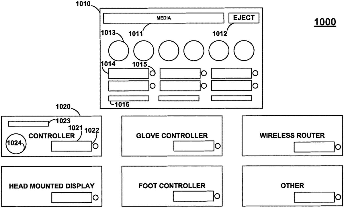
FIG.10shows game system1010that may include, for example, media player1011associated with eject button1012, input/output ports1013that may be used, for example, to coupled HMDs and/or controllers. Game system1010may also include memory slots1016that may receive memory (e.g., compact flash) and read information from, and/or write information to, received memory (e.g., a player's profile and/or particular game information such as the player's progress in a particular game). Game system1010may also include battery slots1014that may, for example, receive a rechargeable battery and recharge the rechargeable battery if, for example, the battery is not already fully charged. Thus, a user may use, for example, a battery powered wireless HMD and a battery powered wireless controller and, when a particular battery needs recharging, a user can simply take out a charged battery in a rechargeable slot, put the battery that needs charging into the rechargeable slot, and then use the charged battery to power the device needing a charged battery. Power indicators1015may be provided that are representative of the amount of charging that has occurred. For example, power indicators1015may be YELLOW when the battery is charging and GREEN when the battery is fully charged. Alternatively, power indicators1015may be RED when the battery has LOW power, YELLOW when the battery has MEDIUM power, and GREEN when the battery has HIGH power. Thus, a user may be able to select the most charged battery when a new battery is needed. Alternatively, power indicators1015may include a percentage number that is indicative of the percentage that the battery is charged. Persons skilled in the art will appreciate that different types of batteries may store different amounts of energy. Thus, power indicators1015may include the amount of time that a battery is expected to operate in a particular device (e.g., a controller). Persons skilled in the art will also appreciate that different devices may consume power at a faster rate than other devices. As such, different batteries may be utilized for different devices and such batteries may be color coded (e.g., batteries for an HMD may be RED while batteries for a controller are GREEN). Different types of batteries may be configured to operate on the same recharging interface or, for example, game system1010may include different types of recharging ports which also may be color coded to correspond to the types of batteries the recharging ports are operable to recharge.
For example, controller1021, or any device, may include a battery port1021with power indicator1022. Battery port1021may be utilized to couple a battery to a controller such that the controller can be powered from a battery in battery port1021. Controller1020may include memory input1023for receiving memory and reading/writing information from/to the memory. Controller1021may include interface1024that is coupled to a wire that may be inserted into port1013. Glove controllers, wireless routers, head mounted displays, foot controllers, or any other additional controller or gaming device may be operable to be powered, at least partially, by a rechargeable battery that can be recharged, for example, by a recharging port on system1010. Persons skilled in the art will appreciate that any controller may include a wire-based link for interfacing with game system1010and any such wire-based link may provide power to the device from system1010. As such game system1010, or any controller or HMD, may include any type and any number of power regulation devices.
FIG.11shows game package schemes1100that may include game package1110,1120, and1130. Persons skilled in the art will appreciate that game systems may be packaged with a variety of different devices and that such packages increase the whimsical and festive nature of both the game system, the devices, and the package itself. Providing packaging with a whimsical and festive nature may directly increase the commercial success of a particular package.
Game package110may include, for example, a console, a head mounted display, a controller, a power converter/regulator/surge protector, cables (e.g., cables to connect to different types of television sets such as coaxial, audio/video, and component cables), a rechargeable battery (or two or more rechargeable batteries), and a remote control (e.g., for playing a media inserted into a media player that is not game media such as a HD DVD movie). Gaming package1110may, for example, include additional components or may include less components. Gaming package1110may, for example, not include a power converter/regulator. Additionally, the controller may, for example, be a wireless (or wire-based) controller and the HMD may be a wire-based (or wireless HMD). Package1120may include, for example, a HMD, wireless controller, television interface cables, and two rechargeable batteries (or one or any number of rechargeable battery). Gaming package1130may include, for example, a console, a controller, and television interface cables. A gaming package may also include, for example, a particular game (and components that are designed around the theme of the game) or a game demo and advertising/operational manuals.
FIG.12shows process1200that may include, for example, step1210in which a game may be transported (e.g., downloaded) or inserted into a HMD, or portable system, for portable play. Step1210may, for example, be utilized to play the game off the source of where the game is being read (e.g., from an insertable game medium in a stationary game system or located in the memory of a remote server) so that the game may be transported (e.g., downloaded) into the portable system (e.g., HMD-based system). Step1210may be utilized to transport the game from a portable, handheld gaming system to the HMD. Persons skilled in the art will appreciate that a game may be transferred from an insertable storage medium (e.g., game disc) into the Random Access Memory (RAM) of a video game system (e.g., a portable game system such as a HMD-based portable game device or a stationary system).
Step1220may be provided, for example, to download the game (or a game portion) to, for example, the memory of the HMD (or removable memory that can be inserted into a HMD or a game system electrically coupled to the HMD).
Step1230may be utilized to determine when a user desires to play a game and the game may be played in step1240. Step1250may be utilized to determine whether the game is over or the game progress is desired to be saved. Step1260may be utilized to upload the game status (e.g., to a remote server or to a game system) and/or store locally in step1270. Step1280may upload game results.
FIG.13shows architecture1300that may be utilized for a game system (e.g., a portable game system or a stationary game system). Persons skilled in the art will appreciate that components may be added to, or removed from, architecture1330. For example, architecture1330may include one or more processors1310, power sources1320, output devices1325, memory1330, connection terminals1335, additional components1340, location/inertial sensing devices1245, manual input controls1350, wireless transmitters/receivers1355, sensory feedback1360(e.g., mechanical rumbler, additional sound maker, light producer), and/or microphones/speakers1365.
FIG.14shows network1400topology that may be utilized. Network1451may be utilized to communicate information from, for example, content facility1480to portable game devices1460or stationary game devices1470. The internet, or an internet, may be utilized to facility the communication. Content facility1480may, for example, allow video games to be downloaded to gaming devices, progress to be uploaded, and scores to be uploaded (for online competitions). Information may be stored on remote databases1481. Persons skilled in the art will appreciate that content facility1480may also be utilized to facility multiplayer games by routing information (e.g., information on the game's progress and player movements) between players that are located remotely from one another.
FIG.15shows portable game system1510that may include game display1520and any number of inertial and/or positioning sensors1530. Portable game system1510may be a wireless telephone (e.g., a cellular phone) that is operable of making telephone calls in addition to playing video games. One or more directional indicia1540may be utilized to show the direction that device1510is moving in. Three dimensional indicia may be utilized to depict the pitch/roll/tilt of a device. As such, system1510may include any number of inertial and positioning devices to determine the direction system1510is facing, the pitch, roll, and tilt of system1510and the velocity and acceleration of system1510in any direction (e.g., how fast the system rolls, pitches, tilts, moves, and/or the distance the system displaces). Additional information may be displayed indicative of the velocity and acceleration of the movement of the device. Multiple controls may be provided as well as multiple speakers and microphones. A portable system may include a game media port for playing new games or the game system may be dedicated to one or more games and may not include a game port (or an ability to wireless download games or play games over a wireless connection).
A location-based game may be provided where a players physical movements correlate to a video game characters virtual movements. Particularly, the location of a device (e.g., the changes in a position of a device) may be utilized to move a virtual character. Such location information may be obtained from any number of positioning systems (e.g., GPS, Galileo, or a local positioning system) and/or inertial sensors. Persons skilled in the art will appreciate that inertial sensors may be utilized to provide a positioning system by utilizing velocity/acceleration/directional information to determine changes in a user's position. Positioning systems may utilize inertial information to update location approximations during periods when the positioning system is unable to update a location approximate on its own (e.g., between receptions of GPS signals).
Persons skilled in the art will appreciate that a game can be programmed to help minimize errors that result from error accumulations in inertial sensors such as accelerometers and gyroscopes. For example, a game may be programmed with narrow passageways at particular points in the game such that the need for complex movement information is minimized (e.g., the game can just determine movement in the direction of the passageway to move a character and does not need to use other movement information). Such passageways can also be utilized to determine errors as a person walking through the passageway would be expected to walk through the passageway and not hit a wall. If the game receives information that a user has hit a wall, the game may be able to assume that such readings are errors and the game can try to negate such errors from future readings. Similarly, a video game character can be told to stop at particular times (e.g., at particular save checkpoints, or level completion points, or when talking to a character) such that inertial errors can be detected and/or inertial systems can be reset and/or recalibrated. Such checkpoints that are built into the game may also allow, for example, some positioning systems (e.g., GPS systems) to update the location before game progress continues such that a reference point is established when a user is not moving.
FIG.16shows game systems1610and1620. A game may be provided in which a character is always aligned with an alignment line (e.g., alignment line1625or1675). Such a line may be, for example, a vertical line or a horizontal line (and may be transparent to a user). Thus, the character will move along the line if movement occurs along the line, but if movement occurs not along the line, the game will scroll such that the game environment moves. Such an alignment line may allow a character to always be positioned in a particular area of the game such that a particular portion of the environment may always be seen on all, or a particular side, or a character. An alignment point may be provided such that the character never moves (e.g., is always center on the screen) and user movements are used to move the character through the virtual environment by scrolling the virtual environment with respect to the virtual character. Such an alignment line may be centered.
FIG.17shows systems1710and1720with a vertical alignment line (e.g., line1725and1775) that is off-centered (e.g., approximately 75-95% on one side of the display).
FIG.18shows game systems1810and1820that may include alignment areas (e.g., alignment areas1825and1875). A character may move freely within an alignment area (e.g., a centered box) but when the character hits the perimeter, the character may not, for example, move through that perimeter. Instead, the game environment may scroll such that the character can always move but is always within the alignment area. Manual game controls may be provided or transparent game controls may be provided (e.g., via positioning and/or inertial movement sensors).
FIG.19shows gaming devices (e.g., dedicated portable gaming devices) that may be shaped similar to a tool used in a game such as, for example, a gun or shovel. For example, a gaming device may be coupled to a shovel and a user may move around a virtual environment my walking with the shovel and the user may dig in a particular location in the virtual environment by stopping and moving the shovel in a particular manner (e.g., digging). The GUI on the shovel may then sense such movement and may switch from displaying one environment (e.g., a treasure map or virtual world) to another display (e.g., a mini-game or digging/action indicia such as a display associated to the particular type of movement).
Persons skilled in the art will appreciate that one or more cameras can be coupled to a HMD, or attached to a particular portion of a user's body (e.g., shoulder). Such a camera may, for example, take video of the user's surroundings. If attached to a HMD, the camera may point towards the front of the HMD such that the camera substantially captures the user's perspective of his/her environment. Such pictures may be processed by the HMD, a game system, or another device and utilized to provide information that may assist in providing a video game. For example, a HMD may have a non-transparent screen, but may provide an augmented reality game by using a camera. More particularly, a camera may continually capture the user's perspective, add video game indicia to the captured pictures/video, and then display the new composite pictures/video to a user on the non-transparent display. Persons skilled in the art will appreciate that such composite pictures/video may be provided on a transparent display. As such, a user may be able to see his/her surroundings while using a non-transparent display so that the user can move freely (e.g., run) in his/her actual environment and interact with video game indicia added to the pictures/video of his/her actual environment. Processing a picture/video of an environment may provide different types of information to a game system. For example, a picture/video may be processed to determine the landscape of a user's environment as well as any objects that are located in the user's environment (e.g., tree). As per another example, processing a picture/video may assist in determining the lighting of a user's environment. Alternatively still, processing a picture/video may assist in determining other players that are in a user's environment. For example, reflective devices may be placed on other HMDs such that processing a picture, or using additional sensors, may determine the location of such reflective devices such that other players can be located. The information from a camera may be shared to other HMDs. For example, if playing a multiplayer game, a user on your team may view a friendly user's camera information such that members of the same team can perform better (e.g., coordinate attacks on an enemy). A camera may also be pointed towards a user's face such that communications to other users may include such camera information. Thus, a user may be able to see another user on a portion of his/her HMD and may communicate to that user.
A video game system may also use a camera to provide picture/video data to a game console to affect the picture/video data that is provided to a stationary television set. For example, a camera may be utilized to capture the picture/video of a player such that the picture/video may be utilized to generate a video game player.
Persons skilled in the art will also appreciate that the present invention is not limited to only the embodiments described. Instead, the present invention more generally involves providing video games. As such, for example, rechargeable battery ports may be utilized in a game system that is not operable to couple to a HMD or gaming devices with inertial/positioning sensors. Persons skilled in the art will also appreciate that the apparatus of the present invention may be implemented in other ways then those described herein. All such modifications are within the scope of the present invention, which is limited only by the claims that follow.
Claims
- A video game console device comprising: a console housing, wherein a video game is operable of being played, said video game having a plurality of selectable video game topologies, a manual input is operable to be received indicative of a selection of at least one of said selectable video game topologies, and said plurality of selectable video game topologies comprises: a virtual reality video game topology operable of displaying said video game in a virtual reality configuration on at least a head-mounted device;and a television set video game topology operable of displaying said video game in a television configuration on at least a television set.
- The video game console device of claim 1, wherein said plurality of selectable video game topologies further comprises an augmented reality video game topology operable of displaying said video game in an augmented reality configuration on a device.
- The video game console device of claim 1, further comprising: a virtual reality port for coupling said head-mounted device, wherein said plurality of selectable game topologies further comprises an augmented reality game topology for displaying said video game in an augmented reality configuration on a device, said virtual reality port is operable to provide virtual reality video game data to said head-mounted device;and a television port for coupling said television, wherein said television port is operable to provide television video game data to said television.
- The video game console device of claim 1, further comprising: a virtual reality port for coupling said head-mounted device, wherein said virtual reality port is operable to provide virtual reality game data to said head-mounted device;and a television port for coupling said television, wherein said television port is operable to provide television game data to said television.
- The video game console device of claim 1, wherein said video game is stored on a media that is removable from, and insertable into, said housing.
- The video game console device of claim 1, further comprising a controller port for coupling to a video game controller and said video game controller is operable to be utilized with said video game.
- The video game console device of claim 1, wherein said manual input is received from a graphical user interface that provides a list of said plurality of selectable game topologies.
- A video game console device comprising: at least one communication receiver, wherein a video game is operable to be played, said video game includes a plurality of selectable video game topologies provided as a result of the detection of a plurality of devices communicatively coupled to said at least one communication receiver, wherein said plurality of selectable video game topologies comprises: a virtual reality video game topology operable to display said video game in a virtual reality configuration on at least a head-mounted device;and a television set video game topology operable to display said video game in a television configuration on at least a television set.
- The video game console device of claim 8, wherein said plurality of selectable video game topologies further comprises an augmented reality video game topology for displaying said video game in an augmented reality configuration on a device.
- The video game console device of claim 8, further comprising: a virtual reality port for coupling said head-mounted device, wherein said virtual reality port is operable to provide virtual reality video game data to said head-mounted device;and a television port for coupling said television, wherein said television port is operable to provide television video game data to said television.
- The video game console device of claim 8, further comprising: a virtual reality port for coupling said head-mounted device, wherein said plurality of selectable game topologies further comprises an augmented reality game topology for displaying said video game in an augmented reality configuration on a device, and said virtual reality port is operable to provide virtual reality game data to said head-mounted device;and a television port for coupling said television, wherein said television port is operable to provide television game data to said television.
- The system of claim 8, wherein said video game is stored on a media that is removable from, and insertable into, said console.
- The video game console device of claim 8, further comprising a controller port for coupling to a video game controller and said video game controller is operable to be utilized with said video game.
- The video game console device of claim 8, wherein said manual input is received from a graphical user interface operable that provides a list of said plurality of selectable game topologies.
- A video game console device comprising: a housing, wherein a video game is operable of being played, said video game includes a plurality of selectable video game topologies, manual input is operable to be received indicative of a selection of at least one of said selectable video game topologies and said plurality of selectable video game topologies comprises: a virtual reality video game topology for displaying said video game in a virtual reality configuration on at least a head-mounted device;and an augmented reality video game topology for displaying said video game in an augmented reality configuration on a device.
- The video game console device of claim 15, wherein said console further comprises: a virtual reality port for coupling said head-mounted device, wherein said virtual reality port is operable to provide virtual reality video game data to said head-mounted device;and a television port for coupling said television, wherein said television port is operable to provide television video game data to a television.
- The video game console device of claim 15, further comprising: a virtual reality port for coupling said head-mounted device, wherein said plurality of selectable game topologies further comprises an augmented reality game topology for displaying said video game in an augmented reality configuration on a device, and said virtual reality port is operable to provide virtual reality game data to said head-mounted device;and a television port for coupling said television, wherein said television port is operable to provide television game data to a television.
- The system of claim 15, wherein said video game is stored on a media that is removable from, and insertable into, said console.
- The video game console device of claim 15, wherein said manual input is received from a graphical user interface that provides a list of said plurality of selectable game topologies.
- The system of claim 15, wherein said head-mounted device is operable to be detected as a virtual reality device.
Disclaimer: Data collected from the USPTO and may be malformed, incomplete, and/or otherwise inaccurate.