U.S. Pat. No. 11,599,137
JOYSTICK ASSEMBLY AND GAME CONTROLLER
AssigneeDEXIN CORP.
Issue DateMay 5, 2022
Illustrative Figure
Abstract
A joystick assembly applicable to a game controller includes a base, a shaft, a movement sensing device, a memory and a processor. The shaft is pivotally disposed at the base. The movement sensing device is disposed in the base and configured to sense the movement of the shaft relative to the base to generate a movement signal. The memory is disposed in the base and stores an identification number of the joystick assembly and pieces of calibration data. The processor is disposed in the base and configured to determine whether to output the movement signal according to the calibration data.
Description
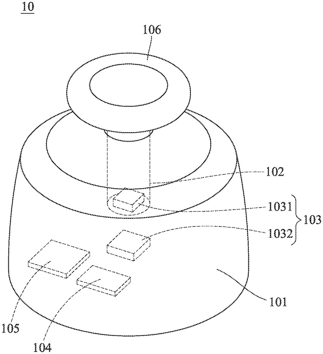
DETAILED DESCRIPTION Please refer toFIG.1, which is a schematic diagram of a joystick assembly according to one embodiment of the present disclosure. As illustrated inFIG.1, the joystick assembly10includes a base101, a shaft102, a movement sensing device103, a memory104and a processor105. The shaft102is pivotally disposed at the base101and a joystick cap106may be installed on the shaft102. It should be noted thatFIG.1exemplarily illustrates the shapes of the base101and the joystick cap106of the joystick assembly10instead of intending to limit the present disclosure. The movement sensing device103is disposed in the base101and is configured to sense the movement of the shaft102relative to the base101to generate a movement signal. The movement sensing device103includes one or more magnetic components1031and a Hall integrated circuit1032. The magnetic component1031may be implemented by a magnet or the other magnetic material and is disposed on the terminal, located in the base101, of the shaft102. The Hall integrated circuit1032may be disposed in the base101and is configured to sense the movement of the magnetic component1031as the shaft102moves relative to the base101to generate a movement signal. Specifically, the Hall integrated circuit1032may include Hall effect sensors and a signal processing circuit, the said Hall effect sensors may respectively detect magnetic field sensing signals, and the signal processing circuit may process the said magnetic field sensing signals to generate digital signals corresponding to the movements on the x-axis and the y-axis as the said movement signal. In another embodiment, the movement sensing device103may comprise at least two potentiometers. The said at least two potentiometers output voltage values corresponding to the movements on the x-axis and the y-axis respectively following the movement of the shaft102relative to the base101, wherein the voltage values serve as the said movement signal. The memory104is disposed in the base101. The memory104may be a read-only memory (ROM), a flash memory, a dynamic random access ...
DETAILED DESCRIPTION
Please refer toFIG.1, which is a schematic diagram of a joystick assembly according to one embodiment of the present disclosure. As illustrated inFIG.1, the joystick assembly10includes a base101, a shaft102, a movement sensing device103, a memory104and a processor105. The shaft102is pivotally disposed at the base101and a joystick cap106may be installed on the shaft102. It should be noted thatFIG.1exemplarily illustrates the shapes of the base101and the joystick cap106of the joystick assembly10instead of intending to limit the present disclosure.
The movement sensing device103is disposed in the base101and is configured to sense the movement of the shaft102relative to the base101to generate a movement signal. The movement sensing device103includes one or more magnetic components1031and a Hall integrated circuit1032. The magnetic component1031may be implemented by a magnet or the other magnetic material and is disposed on the terminal, located in the base101, of the shaft102. The Hall integrated circuit1032may be disposed in the base101and is configured to sense the movement of the magnetic component1031as the shaft102moves relative to the base101to generate a movement signal. Specifically, the Hall integrated circuit1032may include Hall effect sensors and a signal processing circuit, the said Hall effect sensors may respectively detect magnetic field sensing signals, and the signal processing circuit may process the said magnetic field sensing signals to generate digital signals corresponding to the movements on the x-axis and the y-axis as the said movement signal.
In another embodiment, the movement sensing device103may comprise at least two potentiometers. The said at least two potentiometers output voltage values corresponding to the movements on the x-axis and the y-axis respectively following the movement of the shaft102relative to the base101, wherein the voltage values serve as the said movement signal.
The memory104is disposed in the base101. The memory104may be a read-only memory (ROM), a flash memory, a dynamic random access memory (DRAM), a static random access memory (SRAM) or the other non-volatile memory. The memory104may store an identification number of the joystick assembly and pieces of calibration data. The identification number of the joystick assembly may indicate a production batch number of the joystick assembly10. The calibration data may include a static signal and a virtual true circle, and wherein the static signal indicates a signal (such as a voltage value, a current value, etc.) detected by the movement sensing device103when the shaft102is not moved by any external force and the virtual true circle indicates a movement range of the shaft102with respect to the base101. Besides, the memory104may be electrically coupled to the movement sensing device103and may store the signal detected by the movement sensing device103.
Specifically, the memory104may further be controlled to output one or more of the identification number of the joystick assembly, the pieces of calibration data and the signal detected by the movement sensing device103for an external processing device to perform processes of collection, tracking, analysis and so on of the data of the joystick assembly10. In particular, the external processing device may read the identification numbers and the pieces of calibration data of multiple joystick assemblies and accordingly perform a processing procedure of analyzing the calibration data of joystick assemblies that belong to the same production batch number or a processing procedure of comparing the calibration data of joystick assemblies with different production batch numbers and so on. For example, the external processing device may utilize the calibration data of all the joystick assemblies with the same identification number to analyze a yield rate of these joystick assemblies produced in the same production batch.
The processor105is disposed in the base101and is electrically coupled to the movement sensing device103and the memory104. The processor105may be implemented by a central processing unit. In particular, the processor105and the aforementioned memory104may be included in a microcontroller; that is, the processor105and the memory104may be implemented by a processor and a memory in the microcontroller. The processor105is configured to determine whether to output the movement signal or not according to the pieces of calibration data. Specifically, the calibration data may include the static signal and the virtual true circle, and the processor105may utilize the static signal and the virtual true circle to obtain 2D coordinates and may determine whether the 2D coordinates are in the virtual true circle or not. The processor105outputs the movement signal if the 2D coordinates are in the virtual true circle. The processor105does not output the movement signal if the 2D coordinates are not in the virtual true circle. The 2D coordinates and the virtual true circle belong to the same coordinate system. The data contents indicated by the 2D coordinates and the virtual true circle are the same as those described in the former paragraphs and are not repeated. By regarding the virtual true circle as a calibration indicator, there is no need to particularly design structure according to a sensing range of the movement sensing device103of the joystick assembly to limit a moving range of the shaft102, and cost of the structure design is lowered.
In particular, the Hall integrated circuit1032, the memory104and the processor105of the said movement sensing device103may be disposed on one circuit board.
In one embodiment, the movement sensing device103is further configured to generate the static signal associated with the shaft102, a horizontal movement limit signal and a vertical movement limit signal in addition to performing the operation of the aforementioned embodiment. The static signal indicates the signal detected by the movement sensing device103when the shaft102is not moved by any external force. The horizontal movement limit signal indicates the signal detected by the movement sensing device103when the shaft102is moved to the limit on the horizontal direction. The vertical movement limit signal indicates the signal detected by the movement sensing device103when the shaft102is moved to the limit on the vertical direction. In addition to the operation of the aforementioned embodiment, the processor105is further configured to perform zero calibration operation according to the static signal, and to perform virtual true circle calibration operation according to the static signal associated with the shaft102, the horizontal movement limit signal and the vertical movement limit signal, and to store a result of the virtual true circle calibration operation and the static signal into the memory104as the pieces of calibration data.
Specifically, the zero calibration operation performed by the processor105includes regarding the 2D coordinates corresponding to the static signal as the coordinates of the center. The virtual true circle calibration operation performed by the processor105includes: utilizing the static signal and the horizontal movement limit signal to obtain an x-coordinate; utilizing the static signal and the vertical movement limit signal to obtain a y-coordinate; transforming the x-coordinate and the y-coordinate into polar coordinates to obtain a radius; utilizing the radius and the aforementioned coordinates of the center to obtain the virtual true circle as the result of the virtual true circle calibration operation which is one of the pieces of calibration data. The movement of the aforementioned shaft102may be manipulated by a user or a mechanical arm of a testing apparatus and the processor105may be triggered by the user or the testing apparatus to perform the aforementioned calibration operation.
In particular, the piece of calibration data may be obtained by the operation of the movement sensing device103and the processor105before the joystick assembly10is out of the factory. Or, the joystick assembly10may update the calibration data by performing the aforementioned operation of the movement sensing device103and the processor105again.
Please refer toFIG.2, which is a schematic diagram of a game controller according to one embodiment of the present disclosure. As illustrated inFIG.2, the game controller1may include a body11and one or more joystick assemblies10, wherein each joystick assembly10may be pluggably disposed at the body11and may be the joystick assembly10in any one of the aforementioned embodiments. Specifically, the game controller1may further comprise a processing device12. The processing device12is disposed in the body11and may be coupled to the processor105by wire connection or wireless connection. The processing device12may be disposed in a region other than the region where the joystick assembly10is disposed in the body11. The processing device12may be disposed on a circuit board different from the circuit board where the processor105is disposed. The processing device12may be implemented by a microcontroller and is configured to receive the movement signal determined to be output by the processor105according to the pieces of calibration data. The processing device12may perform signal processing on the movement signal or combine the movement signal and a control signal from another control assembly such as a circle button, a D-pad and so on of the game controller1for analysis and/or processing, but the present disclosure is not limited thereto.
By the aforementioned structure, for the joystick assembly and the game controller disclosed by the present disclosure, the joystick assembly itself is provided with the memory and the processor, wherein the memory stores the identification number of the joystick assembly to provide the processes of data collection, data tracking, data analysis and so on. Besides, the memory of the joystick assembly stores the pieces of calibration data for the processor to determine whether to output an input signal or not. In other words, the joystick assembly may complete the calibration before the joystick assembly is out of the factory or is installed in the game controller so as to avoid the problem of the conventional entire equipment that components need to be checked one by one when the signal of the equipment is not good and therefore much calibration is taken.
Claims
- A joystick assembly, applicable to a game controller, comprising: a base;a shaft pivotally disposed at the base;a movement sensing device disposed in the base and configured to sense a movement of the shaft relative to the base to generate a movement signal;a memory disposed in the base and storing an identification number of the joystick assembly and a plurality of pieces of calibration data;and a processor disposed in the base, electrically coupled to the movement sensing device and the memory, and configured to determine whether to output the movement signal or not according to the plurality of pieces of calibration data.
- The joystick assembly according to claim 1, wherein the movement sensing device comprises: a magnetic component disposed on one terminal, located in the base, of the shaft;and a Hall integrated circuit disposed in the base and configured to sense a movement of the magnetic component as the shaft moves relative to the base to generate a digital signal, wherein the digital signal serves as the movement signal.
- The joystick assembly according to claim 1, wherein the memory and the processor are included in a microcontroller.
- The joystick assembly according to claim 1, wherein the plurality of pieces of calibration data comprise a virtual true circle and a static signal and determining whether to output the movement signal or not according to the plurality of pieces of calibration data performed by the processor comprises: utilizing the static signal and the movement signal to obtain 2D coordinates;determining whether the 2D coordinates are in the virtual true circle or not;outputting the movement signal if the 2D coordinates are in the virtual true circle;and not outputting the movement signal if the 2D coordinates are not in the virtual true circle.
- The joystick assembly according to claim 1, wherein: the movement sensing device is further configured to generate a static signal associated with the shaft, a horizontal movement limit signal and a vertical movement limit signal, and the processor is further configured to perform a calibration operation according to the static signal, the horizontal movement limit signal and the vertical movement limit signal and store a result of the calibration operation and the static signal into the memory as the plurality of pieces of calibration data.
- The joystick assembly according to claim 5, wherein performing the calibration operation performed by the processor comprises: utilizing the static signal and the horizontal movement limit signal to obtain an x-coordinate;utilizing the static signal and the vertical movement limit signal to obtain a y-coordinate;and transforming the x-coordinate and the y-coordinate into polar coordinates to obtain a virtual true circle serving as the result of the calibration operation.
- The joystick assembly according to claim 5, wherein the memory is further configured to be controlled to output one or more of the identification number of the joystick assembly and the plurality of pieces of calibration data.
- A game controller comprising: a body;and a joystick assembly according to claim 1, pluggably disposed at the body.
- The game controller according to claim 8, further comprising: a processing device disposed in the body and coupled to the processor, and configured to receive the movement signal determined to be output by the processor according to the plurality of pieces of calibration data.
- The game controller according to claim 8, wherein the movement sensing device comprises: a magnetic component disposed on one terminal, located in the base, of the shaft;and a Hall integrated circuit disposed in the base and configured to sense a movement of the magnetic component as the shaft moves relative to the base to generate a digital signal, wherein the digital signal serves as the movement signal.
- The game controller according to claim 10, further comprising: a processing device disposed in the body and coupled to the processor, and configured to receive the movement signal determined to be output by the processor according to the plurality of pieces of calibration data.
- The game controller according to claim 8, wherein the memory and the processor are included in a microcontroller.
- The game controller according to claim 12, further comprising: a processing device disposed in the body and coupled to the processor, and configured to receive the movement signal determined to be output by the processor according to the plurality of pieces of calibration data.
- The game controller according to claim 8, wherein the plurality of pieces of calibration data comprise a virtual true circle and a static signal and determining whether to output the movement signal or not according to the plurality of pieces of calibration data performed by the processor comprises: utilizing the static signal and the movement signal to obtain 2D coordinates;determining whether the 2D coordinates are in the virtual true circle or not;outputting the movement signal if the 2D coordinates are in the virtual true circle;and not outputting the movement signal if the 2D coordinates are not in the virtual true circle.
- The game controller according to claim 14, further comprising: a processing device disposed in the body and coupled to the processor, and configured to receive the movement signal determined to be output by the processor according to the plurality of pieces of calibration data.
- The game controller according to claim 8, wherein: the movement sensing device is further configured to generate a static signal associated with the shaft, a horizontal movement limit signal and a vertical movement limit signal, and the processor is further configured to perform a calibration operation according to the static signal, the horizontal movement limit signal and the vertical movement limit signal and store a result of the calibration operation and the static signal into the memory as the plurality of pieces of calibration data.
- The game controller according to claim 16, further comprising: a processing device disposed in the body and coupled to the processor, and configured to receive the movement signal determined to be output by the processor according to the plurality of pieces of calibration data.
- The game controller according to claim 16, wherein performing the calibration operation performed by the processor comprises: utilizing the static signal and the horizontal movement limit signal to obtain an x-coordinate;utilizing the static signal and the vertical movement limit signal to obtain a y-coordinate;and transforming the x-coordinate and the y-coordinate into polar coordinates to obtain a virtual true circle serving as the result of the calibration operation.
- The game controller according to claim 18, further comprising: a processing device disposed in the body and coupled to the processor, and configured to receive the movement signal determined to be output by the processor according to the plurality of pieces of calibration data.
- The game controller according to claim 16, wherein the memory is further configured to be controlled to output one or more of the identification number of the joystick assembly and the plurality of pieces of calibration data.
Disclaimer: Data collected from the USPTO and may be malformed, incomplete, and/or otherwise inaccurate.