U.S. Pat. No. 11,577,173
CONTROLLER SUPPORT FOR VIRTUAL REALITY VIDEO GAMES
AssigneePROTUBEVR
Issue DateSeptember 28, 2020
Illustrative Figure
Abstract
A controller support for virtual reality video games, where the support is presented in the form of a stick simulating an object in the virtual reality video game, at least one housing is adapted to receive a controller by interlocking, the controller housing is secured to the stick by way of a pin, the controller housing is grippable and configured to be removably engaged on the pin, a magnetic connection exerting a magnetic force ensures the holding in position of the controller housing on the pin, the magnetic connection is configured such that the engagement/disengagement of the controller housing on the pin is done by a lateral movement of said housing, the magnetic force being oriented in the direction of this lateral movement.
Description
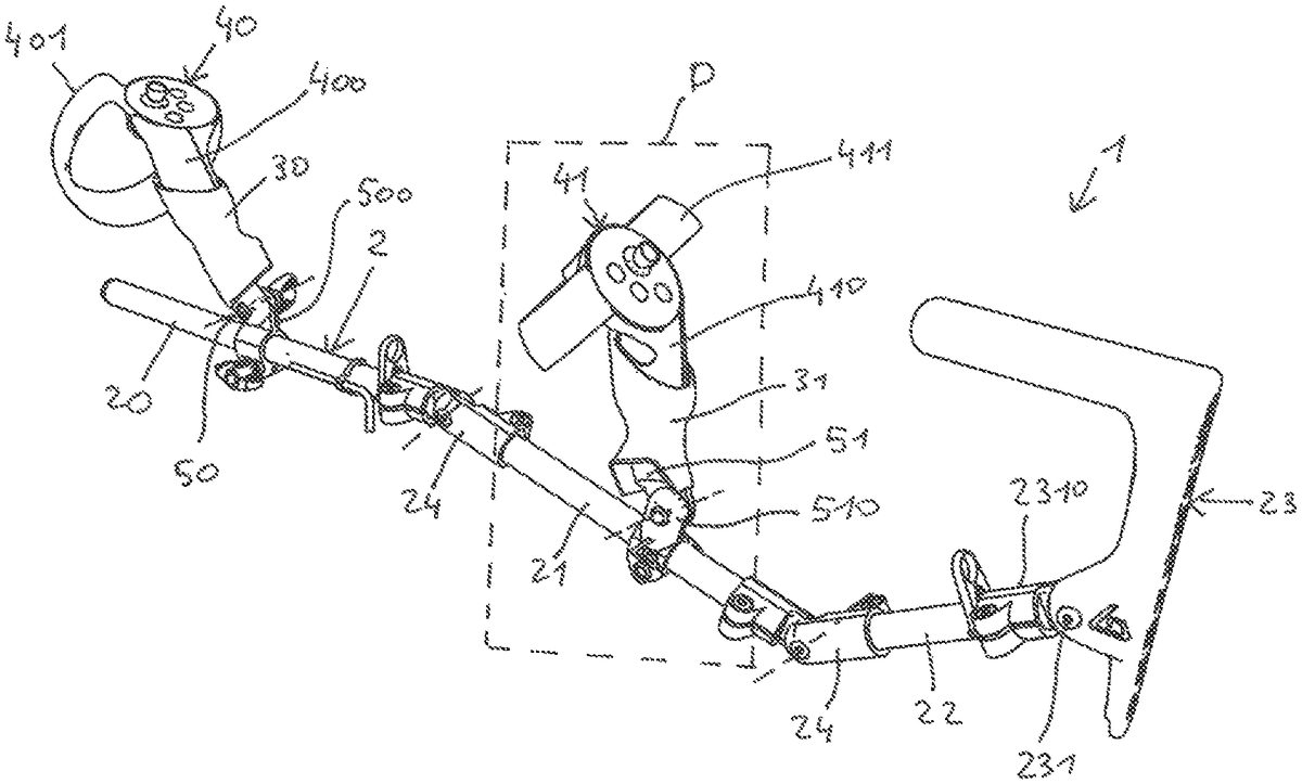
DETAILED DESCRIPTION By referring toFIGS.1and2, the controller support1which is the subject matter of the invention is presented in the form of a stick. This stick2simulates an object in the virtual environment of the video game, in particular a gun, but also other objects such as a handgun, sword, stick, golf club, fishing rod, etc. In other words, the stick2forms a virtual simulated object. The stick2can be straight, curved or be presented in the form of a broken line. It has the function, in particular, of physically connecting the controllers together and to hold them in a certain alignment. According to a preferred embodiment illustrated inFIGS.1and2, the stick2has four portions20,21,22,23articulated together: a front portion20, a middle portion21, a rear portion22and a crosier23. An advantage linked to the use of an articulated stick2is that this can be easily folded (FIG.8), and that in this folded state, the support1has a reduced bulk, such that it can be easily stored and/or transported. Furthermore, the player has the possibility to shape the stick2to adapt it to the morphology thereof, and/or to the virtual simulated object type used in the video game. The front20, middle21and rear 22 portions are presented advantageously in the form of rigid tubes, made of metal, plastic, wood, carbon, etc. The tubes can be cylindrical, of round, oval, square, rectangular cross-section, etc. The length thereof is, for example, comprised between 15 cm and 30 cm and the outer diameter thereof, for example, comprised between 1 cm and 5 cm. These portions can have the same length or different lengths. InFIGS.1and2, the rear portion22is, for example, shorter than the front20and middle21portions. The portions20,21and22are advantageously connected together by means of articulated tube connectors24with two junctions240. These connectors24each form a pivot connection of horizontal axis. The articulations of the connectors24are preferably notched, such that the ...
DETAILED DESCRIPTION
By referring toFIGS.1and2, the controller support1which is the subject matter of the invention is presented in the form of a stick. This stick2simulates an object in the virtual environment of the video game, in particular a gun, but also other objects such as a handgun, sword, stick, golf club, fishing rod, etc. In other words, the stick2forms a virtual simulated object.
The stick2can be straight, curved or be presented in the form of a broken line. It has the function, in particular, of physically connecting the controllers together and to hold them in a certain alignment.
According to a preferred embodiment illustrated inFIGS.1and2, the stick2has four portions20,21,22,23articulated together: a front portion20, a middle portion21, a rear portion22and a crosier23. An advantage linked to the use of an articulated stick2is that this can be easily folded (FIG.8), and that in this folded state, the support1has a reduced bulk, such that it can be easily stored and/or transported. Furthermore, the player has the possibility to shape the stick2to adapt it to the morphology thereof, and/or to the virtual simulated object type used in the video game.
The front20, middle21and rear 22 portions are presented advantageously in the form of rigid tubes, made of metal, plastic, wood, carbon, etc. The tubes can be cylindrical, of round, oval, square, rectangular cross-section, etc. The length thereof is, for example, comprised between 15 cm and 30 cm and the outer diameter thereof, for example, comprised between 1 cm and 5 cm. These portions can have the same length or different lengths. InFIGS.1and2, the rear portion22is, for example, shorter than the front20and middle21portions.
The portions20,21and22are advantageously connected together by means of articulated tube connectors24with two junctions240. These connectors24each form a pivot connection of horizontal axis. The articulations of the connectors24are preferably notched, such that the player can adjust the shaping of the stick2suitably, then block in position the portions20,21and22once the shaping is done.
The crosier23can be made of the same material as the articulated portions20,21,22,23or made of a different material. To simplify the design thereof, it is obtained by plastic molding. InFIGS.1and2, this crosier23has a general L-shape, of which one branch230is mounted on an articulation231. The other branch232is oriented in the same direction as the stick2, towards the front portion20. The branch232forms a cheek support, particularly useful for the player when they want to adjust a shot.
The articulation231forms a pivot connection of horizontal axis enabling a rotation of the crosier23with respect to the axis of the stick2. By “axis of the stick”, this means here the longitudinal axis of the stick2when this is rectilinear, or the longitudinal axis of the rear portion22when said stick is not rectilinear. The articulation231is presented preferably in the form of a notched articulation including a portion2310wherein an end of the rear portion22is fixedly interlocked. The notching makes it possible for the player to adjust the inclination of the crosier23suitably, then to block it in position once this adjustment is carried out.
The support1is provided with two housings30,31adapted to each receive a controller40,41. These housings30,31can be made of metal, plastic, carbon, etc. In the appended figures, they are arranged on the front20and middle21portions of the stick2.
By referring, in particular, toFIG.7, the controller40,41includes a stick400,410at the end of which is arranged a ring401,411supporting the sensors/transmitters4010,4110.
Each housing30,31has the shape of a goblet or cup wherein the stick400,410of the controller40,41is interlocked. This interlocking is done along the axis of the stick400,410, and generally according to a movement from the top to the bottom. The inner dimensions of the housing30,31are adjusted to those of the stick400,410such that the stick400,410is held in position quite firmly. The inner dimensions of the housing30,31are adapted to the controller model used by the player (VIVE®, OCULUS RIFT®, ACER®, LENOVO®, and SAMSUNG®, HP®, DELL®), such that the stick400,410is engaged with a clamped adjustment in said housing30,31. Therefore, a specific housing can be provided by controller model. To improve the holding in position of the stick400,410in the housing30,31, the inner walls of the latter are advantageously covered with a coating of the rubber or silicone type, ensuring an additional adherence.
InFIG.7, the stick400,410is provided with a strap or hand strap402,412adapted to be passed around the wrist of the player to avoid the controller40,41falling if it is accidentally dropped during handling. To conserve this attachment when the stick400,410is interlocked in the housing30,31, the wall of the latter includes a hole for the passage300of the strap402,412.
Each housing30,31is secured to the stick2by way of a pin50,51. These pins50,51protrude upwards from the stick2such that said stick is located positioned under the controllers40,41. The sensors/transmitters4010,4110carried by the rings401,411are thus perfectly discovered when the controllers40,41are interlocked in the respective housing30,31thereof, no element of the support1hiding them.
Each pin50,51is preferably made of a non-magnetic material such as plastic, wood, carbon, etc. It can have a round, oval, square, rectangular cross-section, etc. The height thereof is, for example, comprised between 1 cm and 10 cm and the width/thickness thereof, for example, comprised between 0.5 cm and 5 cm.
Advantageously, each pin50,51is mounted on an articulation500,510enabling a rotation of the housing30,31in a plane passing through the axis of the stick2, and starting a rotation of the controller40,41. By “axis of the stick”, this means here the longitudinal axis of the stick2when this is rectilinear or, when said stick is not rectilinear, the longitudinal axis of the portion20,21on which is arranged the housing30,31. The player thus has the possibility to precisely adjust the inclination of each controller40,41, for example to optimize the precision of a shot.
The mounting of a pin51on an articulation510clearly appears inFIGS.4aand4b, being understood that the mounting of the other pin50on the other articulation500is identical. The articulation510advantageously includes a clamping collar5100making it possible to hold it in position on the portion21, with a possibility of angular articulation around the longitudinal axis of said portion. Also, the two articulations500and510are not necessarily aligned but can be off-center according to the adjustment needs of the player. The clamping collar5100is surmounted by a portion carrying the axis of rotation5110. The latter is perpendicular or substantially perpendicular to the longitudinal axis of the portion21. The axis of rotation5110is presented, for example, in the form of a rod or a screw also in contact with the pin51.
A notched interface can be provided between the pin51and the articulation510, such that the player can adjust the inclination of said pin (and therefore of the housing31) suitably, then block it in position once this adjustment is made. Also, a notched articulation can be provided at the level of a pin and a smooth articulation at the level of the other pin. For example, by referring toFIGS.1and2, the front articulation500can be smooth while the rear articulation510is notched. Such a configuration offers the player the possibility of modifying, at any time, the inclination of the front controller40, for example to adapt it to a game sequence, while the other rear controller41remains with a fixed inclination. The two articulations500,510can also both be smooth articulations.
According to a feature of the invention, the housings30,31are grippable and are removably engaged on the pins50,51. To disengage a controller40,41of the stick12, the player must therefore handle it by holding the housing wherein it is interlocked, which housing is thus substituted for the stick400,410of said controller. To improve the gripping of the housings30,31, the outer wall thereof can be shaped ergonomically to be adapted to the player's hand.
The inventor has observed that a lateral movement of the housing30,31to engage/disengage the stick40,41of the stick2was a lot more natural and intuitive for the player, than a transversal movement from bottom to top or from top to bottom, like with MAMUT®, MAGNETIC VIVE RIFLE VR or ProTubeVR® supports known to date.
FIG.5shows a support1as a top view, the plane of the drawing board corresponding to the transversal plane of the stick2. The lateral movement of the housings30,31is a side movement with respect to the axis A-A of the stick2, which side lateral movement is illustrated by double arrows. The player must hold the housing30,31and carry out a lateral translation and/or rotation of their hand or of their forearm to engage/disengage it from the pin thereof. By referring toFIG.6, this lateral movement can be done perpendicularly to the sagittal median plane P of the stick2(according to the arrow F1) or according to a solid angle ‘S’ less than or equal to 0.5 steradian (Pi/6 for an equivalent plane angle), the axis of this solid angle being normal to the sagittal median plane P of said stick.
FIG.5illustrates a configuration for a right-handed player, where the player holds the front housing30with the left hand and the rear housing31with their right hand. The most natural and intuitive movement for the player consists of disengaging the front housing30by carrying out a movement from right to left and to reengage by a movement from left to right. Conversely, the rear housing31is disengaged by carrying out a movement from left to right and reengaged by a movement from right to left.
A left-handed player will hold the front housing30with their right hand and the rear housing31with their left hand. The most natural and intuitive movement for this player consists of disengaging the front housing30by carrying out a movement from left to right and to reengage it by a movement from right to left. The rear housing31will be disengaged by carrying out a movement from right to left and reengaged by a movement from left to right.
Preferably, it is a magnetic connection exerting a magnetic force which ensures the holding in position of the housing30,31on the pin50,51. Thus, a connection is obtained by “magnetic clipping”. This magnetic connection is configured such that the engagement/disengagement of the housing30,31on the pin50,51is carried out by a lateral movement of said housing, the magnetic force being oriented in the direction of this lateral movement, i.e. according to the arrows illustrated inFIGS.5and6. The direction of the magnetic force is therefore normal to the sagittal plane P of the stick2or oriented according to the abovementioned solid angle ‘S’.
In practice, when the player has a virtual reality headset covering their eyes, a controller40,41held in one hand and disconnected from the stick2, it comes to find, quite intuitively, the approximate position of the pin30,31. Once near the pin50,51, it is the magnetic force which will finish guiding the housing30,31towards said pin. The magnetic connection therefore has two functions: ensuring the holding in position of the housing30,31on the pin50,51; and directing the housing30,31in a determined return direction when it is in the proximity of said pin50,51.
InFIGS.4aand4b, the housing31includes a magnetized portion63engaging with a metal portion65arranged on the pin51. An inverse configuration can be considered where the housing31includes a metal portion63engaging with a magnetized portion65arranged on the pin51. The best results are obtained when the housing30,31and the pin50,51both include a magnetized portion which engage together. Preferably, permanent magnets are used, each exerting a force equivalent to about 11 kg (the equivalent of the force (weight) exerted by a mass of about 11 kg in the average field of the Earth's gravity). This type of magnet is a good compromise between an effective adherence of the housing30,31on the pin50,51; an easy disengagement of the housing30,31by a lateral movement; and a good magnetic guidance during the reengagement phase of the housing30,31on the pin50,51.
InFIGS.4aand4b, the housing31has a reservation delimited by a side wall330and a bottom wall331. This bottom wall331is preferably situated in a plane parallel to the sagittal median plane P of the stick2and/or in a plane perpendicular to the direction of the magnetic force. The side wall330has a U-shaped or C-shaped cross-section. The side wall330thus covers the upper portion of the pin51when said housing is engaged on said pin. The pin51, and in particular the upper portion thereof, has a complementary shape of the reservation of the housing31so as to ensure an adjusted interlocking of these two elements.
The side wall330is oriented in the direction of the lateral engagement/disengagement movement of the housing31on the pin51. It thus acts as a guide during engagement/disengagement phases of the housing31. This guiding is improved when the side wall330is flared, i.e. which goes by enlarging from the bottom wall331. The side wall330thus has the general shape of a three-sided frustum of pyramid.
During particularly active game sequences, it can occur that the player suddenly urges the controllers40,41assembled on the stick2. It is, for example, the case during a shooting game sequence where numerous enemies must be eliminated rapidly or during a fishing game sequence where the player must fire on their fishing rod to hit a fish outside of the water. In this type of sequence, the controllers40,41are generally urged in the axis of the stick2, by a sudden front/rear movement. To not impede the virtual experience of the player, it is important that the housings30,31are not disconnected from the pins50,51following these sudden movements. To do this, and as illustrated inFIGS.4aand4b, the side wall330includes at least one, preferably two active surfaces3301,3302, which each come into contact with a complementary surface5101,5102of the covered portion of the pin51,52when said housing is engaged on said pin and when said housing is urged in the axis of the stick2. In the embodiment ofFIG.4a, the active surface3301comes into contact with the active surface5101when the housing31is urged in the axis A-A of the stick2, towards the right of the drawing board, and the opposite active surface3302comes into contact with the complementary active surface5102when the housing31is urged in the axis A-A of the stick2, towards the left of the drawing board.
Thus shaped, the reservation of the housing31and the portion of the pin51which is covered by this reservation, form stop elements which come into contact when said housing is engaged on said pin and which engage when said housing is urged in the axis A-A of the stick2. However, these stop elements do not engage when the housing31is urged laterally, so as to enable the engagement/disengagement of said housing.
When these stop elements come into contact and engage, they make it possible also for the player to transmit the pair making it possible to adjust the inclination of a pin50and/or51when this is mounted on an articulation500,510.
InFIGS.4aand4b, the magnetized portion63arranged on the housing31is arranged at the level of the bottom wall331and held on the latter by screwing or gluing. The magnetized portion65arranged on the pin51is itself arranged at the level of a side wall of said pin, which side wall is opposite the bottom wall331when the housing31is engaged on said pin. The magnetized portion65is also held on the wall of the pin51by screwing or gluing.
According to an advantageous feature of the invention illustrated inFIGS.9aand9b, the magnetized portions63and65are each presented in the form of a potted magnet. In this type of mounting, the magnet630,650(having North ‘N’ and South ‘S’ poles) is inserted inside a steel cup631,651forming a “pot”. The poles of the magnets630,650are inverted so as to generate an attraction force of the magnetized portions63and65. When the magnetized portions63,65are in contact with one another (FIG.9a), the edges of the cups631,651are in contact, the magnets630,650could be in slight withdrawal from these edges such that they are not in direct contact. The cups631,651all deviate the lines of the magnetic field in the direction of the contact surface. The magnetic force is thus concentrated on the contact surface, which actually improves the adherence of the housing30,31on the pin50,51. Furthermore, the inventor has observed that these potted magnets would contribute to a self-centering of the housing30,31on the pin50,51.
By referring toFIGS.4aand4b, the reservation of the housing31has a lug332which projects from the bottom wall331. This lug332is situated at the level of the free side of the bottom wall331, i.e. the side with no side wall330. The lug332is configured to be engaged against an active surface5132of the pin51, when the housing31is engaged on the latter. The engagement of the lug332and of the active surface5132makes it possible to finalize the self-centering of the housing30,31on the pin50,51.
The lug332and the active surface5132can also form a connection by mechanical clipping contributing to the holding in position of the housing30,31on the pin50,51. This connection by mechanical clipping complements the connection by magnetic clipping described above. In an embodiment variant not covered by the invention, the holding in position of the housing30,31on the pin50,51is only endured by this connection by mechanical clipping.
The arrangement of the different elements and/or means and/or steps of the invention, in the embodiments described above, must not be comprised as requiring such an arrangement in all the implementations. In any case, it will be understood that various modifications can be applied to these elements and/or means and/or steps, without deviating from the sense and the scope of the invention. In particular:
The stick2can be simply one single holding, without articulation, or only include two articulated portions, including the rear crosier.
One single housing30or31can be secured to the stick2.
The pins50,51can be made of metal or steel.
Each pin30,31, or only one of them, can be fixedly mounted on the stick2, i.e. without possibility of rotation, for example by screwing or welding.
Only one of the two housings30,31can be removably engaged on the pin50,51thereof, the other housing being fixedly mounted on the pin thereof, i.e. without possibility of disengagement during the game.
The side wall330of the reservation arranged in the housing30,31can have the general shape of a cone frustum, or any other shape suitable for a person skilled in the art, the pin51or at least one portion of it thus having a complementary shape of this reservation.
Claims
- A controller support for virtual reality video games, comprising: a stick having a shaft, wherein the stick has a longitudinal axis along the entirety of the shaft or having a portion comprising a longitudinal axis along the entirety of the shaft, and at least one grippable housing adapted configured to receive a game controller by interlocking, the controller housing is secured to the stick, wherein the controller housing is secured to the stick or to the stick's portion by way of a pin, the controller housing is configured to be removably engaged on the pin, a magnetic connection exerting a magnetic force ensures the holding in position of the controller housing on the pin, the magnetic connection is configured such that the engagement/disengagement of the controller housing on the pin is done by a lateral movement of said housing, the lateral movement of the housing is in a perpendicular direction with respect to the longitudinal axis, the magnetic force being oriented in the direction of this lateral movement.
- The controller support according to claim 1, wherein the direction of the magnetic force is normal to the sagittal median plane of the stick or oriented according to a solid angle less than or equal to 0.5 steradian, the axis of this solid angle being normal to said sagittal median plane, said sagittal median plane including the longitudinal axis.
- The controller support according to claim 2, wherein the controller housing includes a magnetized portion, respectively a metal portion, engaging with a metal portion, respectively magnetized, arranged on the pin.
- The controller support according to claim 2, wherein the controller housing includes a magnetized portion engaging with another magnetized portion arranged on the pin.
- The controller support according to claim 1, wherein the controller housing includes a magnetized portion, respectively a metal portion, engaging with a metal portion, respectively magnetized, arranged on the pin.
- The controller support according to claim 1, wherein the controller housing includes a magnetized portion engaging with another magnetized portion arranged on the pin.
- The controller support according to claim 1, wherein the controller housing includes a reservation which covers a portion of the pin when said housing is engaged on said pin, which reservation is delimited by a side wall and a bottom wall.
- The controller support according to claim 7, wherein the side wall of the reservation is oriented in the direction of the lateral movement making it possible for the engagement/disengagement of the controller housing, such that said side wall acts as guiding for said housing during the engagement/disengagement thereof of the pin.
- The controller support according to claim 8, wherein the controller housing includes a magnetized portion, respectively a metal portion, engaging with a metal portion, respectively magnetized, arranged on the pin, and wherein the magnetized portion of the controller housing is arranged at the level of the bottom wall.
- The controller support according to claim 8, wherein the controller housing includes a magnetized portion engaging with another magnetized portion arranged on the pin and the magnetized portion of the controller housing is arranged at the level of the bottom wall.
- The controller support according to claim 7, wherein the controller housing includes a magnetized portion, respectively a metal portion, engaging with a metal portion, respectively magnetized, arranged on the pin, and the magnetized portion of the controller housing is arranged at the level of the bottom wall.
- The controller support according to claim 7, wherein the side wall of the reservation includes at least one surface which comes into contact with a complementary surface of the covered portion of the pin when said housing is engaged on said pin and when said housing is urged in the axis of the stick.
- The controller support according to claim 7, wherein the controller housing includes a magnetized portion engaging with another magnetized portion arranged on the pin, and wherein the magnetized portion of the controller housing is arranged at the level of the bottom wall.
- The controller support according to claim 1, wherein the pin is mounted on an articulation enabling a rotation of the controller housing in a plane passing through the axis of the stick.
- The controller support according to claim 1, wherein the stick has at least two portions articulated together, each of said portions is provided with a controller housing mounted on an articulation.
- The controller support according to claim 1, wherein the stick includes a crosier of which one portion is shaped so as to form a cheek support, which crosier is mounted on an articulation enabling a pivoting of said crosier with respect to the axis of said stick.
- The controller support according to claim 1, wherein a connection by mechanical clipping contributes to the holding in position of the controller housing on the pin.
- The controller support according to claim 1, wherein the controller housing includes inner walls covered with a rubber or silicone coating.
- The controller support according to claim 1, wherein the controller has a stick provided with a strap configured to be passed around the wrist of the player, the controller housing having a wall including a hole for the passage of said strap.
Disclaimer: Data collected from the USPTO and may be malformed, incomplete, and/or otherwise inaccurate.