U.S. Pat. No. 11,547,934
GAME CONTROLLER COMPRISING AT LEAST ONE PIVOTING CONTROL MEMBER WITH A MODIFIABLE STOP ANGLE
AssigneeNACON
Issue DateApril 22, 2021
Illustrative Figure
Abstract
A game controller (1) including an assembled shell (2) and at least one pivoting control member (3) which passes through the assembled shell (2) and can be tilted manually in all directions from a rest position into which it returns in a rotationally elastic manner. For each pivoting control member (3), the game controller includes at least one removable first head (32A) and one removable second head. The two removable heads have different dimensions so as to obtain different values for the stop angle of the control member (3) in relation to its rest position when the control member (3) is tilted in abutment in the stop position.
Description
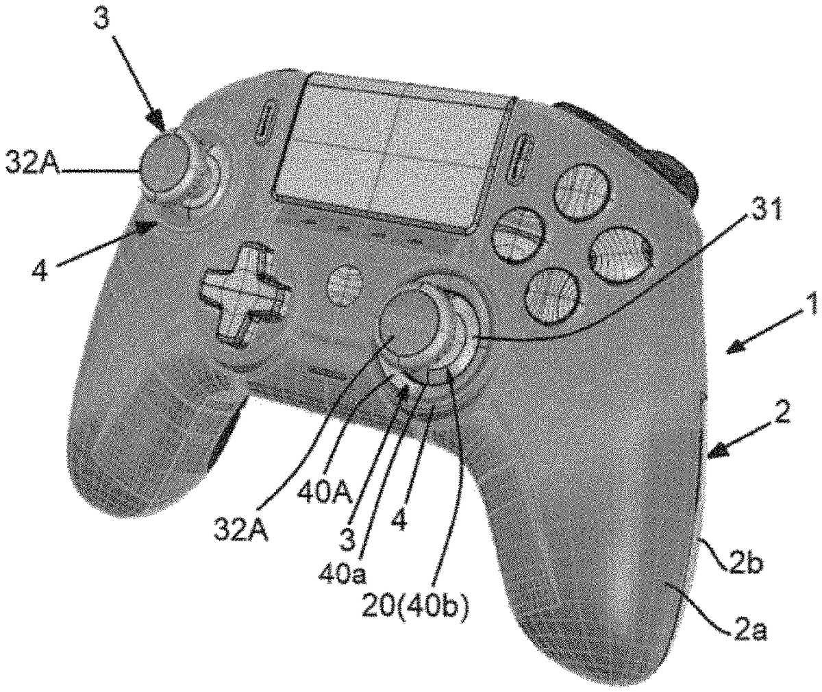
DETAILED DESCRIPTION FIG.1shows a particular example of a game controller1comprising an assembled shell2, and control means in particular comprising two pivoting control members3: a pivoting member3located in the left part of the game controller1and a pivoting member3located in the right part of the game controller1. The assembled shell2comprises, in a manner known per se, an upper half-shell2a, which is assembled by any means, for example mechanically by means of screws or the like and/or by gluing and/or by welding, with a lower half-shell2b. In this particular example, the assembled shell2more particularly has an ergonomic shape adapted to facilitate gripping thereof with both hands by a player. Each pivoting member3is passed through an opening20of the upper half-shell2a, more particularly a circular opening20. More particularly in this specific embodiment, with reference toFIGS.1and3, and in a nonlimiting manner relative to the invention, at each circular opening20of the upper half-shell2a, the game controller1comprises a cylindrical tubular insert4, which is mounted in an opening20of the upper half-shell2aof the controller2, and is fastened to the upper half-shell2a. The upper part of this insert4is provided with a ring40A whose inner edge40adelimits a circular opening40b(FIG.3) of smaller diameter than the diameter of the opening20of the shell2. When this tubular insert4is mounted and is fastened in a circular opening20of the upper half-shell2aof the game controller1, the circular opening40bof this tubular insert4is centered relative to this opening20. In another variant embodiment, the game controller may not comprise such a tubular insert4, and/or may not comprise a ring40A. In the absence of ring40A, the aforementioned inner edge40ais replaced by the inner edge of the opening20in the upper half-shell2aof the game controller. In another variant embodiment, the ring40A can be an integral part of the upper half-shell2aor be an add-on part, which can be fixed permanently or removably to the tubular insert4or ...
DETAILED DESCRIPTION
FIG.1shows a particular example of a game controller1comprising an assembled shell2, and control means in particular comprising two pivoting control members3: a pivoting member3located in the left part of the game controller1and a pivoting member3located in the right part of the game controller1.
The assembled shell2comprises, in a manner known per se, an upper half-shell2a, which is assembled by any means, for example mechanically by means of screws or the like and/or by gluing and/or by welding, with a lower half-shell2b.
In this particular example, the assembled shell2more particularly has an ergonomic shape adapted to facilitate gripping thereof with both hands by a player.
Each pivoting member3is passed through an opening20of the upper half-shell2a, more particularly a circular opening20.
More particularly in this specific embodiment, with reference toFIGS.1and3, and in a nonlimiting manner relative to the invention, at each circular opening20of the upper half-shell2a, the game controller1comprises a cylindrical tubular insert4, which is mounted in an opening20of the upper half-shell2aof the controller2, and is fastened to the upper half-shell2a. The upper part of this insert4is provided with a ring40A whose inner edge40adelimits a circular opening40b(FIG.3) of smaller diameter than the diameter of the opening20of the shell2. When this tubular insert4is mounted and is fastened in a circular opening20of the upper half-shell2aof the game controller1, the circular opening40bof this tubular insert4is centered relative to this opening20.
In another variant embodiment, the game controller may not comprise such a tubular insert4, and/or may not comprise a ring40A. In the absence of ring40A, the aforementioned inner edge40ais replaced by the inner edge of the opening20in the upper half-shell2aof the game controller. In another variant embodiment, the ring40A can be an integral part of the upper half-shell2aor be an add-on part, which can be fixed permanently or removably to the tubular insert4or directly at the opening20of the upper half-shell2a.
In the particular embodiment ofFIG.1, each pivoting member3is of the “joystick” type, and is positioned near the edge of the shell2, so as to be able to be easily manipulated by the left thumb or the right thumb of a player holding the game controller.
Each pivoting control member3of the game controller1is formed by a monolithic assembly of several elements30,31,32A, which will now be described with reference toFIGS.2and4.
Pivoting Control Member3
The element30(FIG.2) of each pivoting control member3is a base element which is intended to be mounted and fixed permanently with respect to the shell2of the game controller. This base element30of each pivoting control member3is known and will therefore be described briefly below.
With reference toFIG.2, this base element30comprises a cylindrical shaft (“stick”)300, with a central axis300a, which is mounted to pivot relative to a casing301. This pivoting cylindrical shaft300is able to be tilted manually with respect to the casing301, in all directions, from a central rest position, illustrated inFIGS.1and2, into which it returns in a rotationally elastic manner. The means for elastically rotating into the central rest position of this shaft300are known and will therefore not be described in detail. These elastic return means, of the spring type, are housed inside the casing301.
This pivoting shaft300is also, and in the usual manner, coupled to analog displacement sensors, for example potentiometer-type sensors, which are housed inside the casing301, and which make it possible to measure the angles of rotation of this shaft300, respectively about two reference axes of rotation, which are perpendicular to each other and which define a plane perpendicular to the central axis300aof the shaft300in its rest position inFIG.2. In a known manner, these sensors deliver analog measurement signals which are characteristic of the instantaneous value of the angle formed by the central axis300aof the shaft300, about each reference axis of rotation, with respect to the rest position of this axis300a.
The base element30is mounted and fastened to the inside of the shell2of the game controller1, so that on the one hand its casing301is fully housed inside the assembled shell2and is fastened to the assembled shell2, and on the other hand its pivoting shaft300is positioned perpendicular to the circular opening40bof the ring40of the insert4described above and is centered with respect to this circular opening40b.
The element31of each pivoting control member3is a protective part which is symmetrical and rigid, and which comprises:in the lower part, a dome-shaped cup310
andin the upper part, a cylindrical assembly end piece311, which is centered relative to the lower cup310, the central axis of symmetry of the cup310being coincident with the central axis of symmetry of this cylindrical end piece311.
More particularly, the cylindrical assembly end piece311comprises a cavity311a(FIGS.2and4) which is open at the top and which is delimited by a bottom wall311band a side wall311c, which is preferably cylindrical. The bottom wall comprises (FIG.3) a projecting central lug311d. The side wall311ccomprises preferably diametrically opposed assembly slots311e.
Referring toFIG.3, the protective element31further comprises, in its lower part, a central cylindrical housing312. This central cylindrical housing312is dimensioned so as to allow a tight fitting in this housing312of the pivoting shaft300of the base element30. The cross-section of this cylindrical housing312and the cross-section of the pivoting shaft300are not circular and are chosen so as to allow the pivoting shaft300to be blocked in rotation about its central axis in this housing312. The element31is mounted simply by axially fitting the element31onto the pivoting shaft300of the base element30.
The cup310of the protective element31is dimensioned such that its maximum external diameter is greater than the diameter of the opening40bof the ring40of the insert4. The cup of the element31makes it possible to partially close the opening40bof the insert4, without hindering the pivoting of the shaft300of the base element30, which makes it possible in particular to avoid the accidental introduction of foreign bodies or elements inside the assembled shell2and also makes it possible to improve the aesthetic appearance of the game controller1.
The element32A constitutes the head of the pivoting control member3and, once mounted, is positioned (FIG.1) on the outside of the assembled shell. This head32A has a geometry and dimensions suitable for the manipulation by a player of the pivoting control member3, preferably using one of his two thumbs.
More particularly, this head32A is removable so that it can be easily and quickly mounted or removed by a user, in particular without having to disassemble the shell2from the game controller1.
In this particular example, this head32A is a single piece, for example made of injected plastic.
This head32comprises a substantially disc-shaped upper part320and a lower cylindrical part321, with height H, which is oriented perpendicular to said disc-shaped upper part320, and which is centered with respect to said disc-shaped upper part320. This cylindrical lower part321forms the foot of the head32A.
In another variant embodiment, the substantially disc-shaped upper part320and the cylindrical foot321could be two sub-elements assembled together by any means, in a permanent and robust manner.
The upper face320aof the head32A can for example be curved and concave as illustrated inFIG.4. In another variant, the upper face320aof the head32A may for example be domed and convex or may be planar.
The cylindrical foot321of the head32comprises a cylindrical outer part3210and an inner part3211, positioned inside the cylindrical outer part3210.
More particularly, the cylindrical outer part3210of the foot321comprises an outer face3210a, which forms, over the entire height H of the foot321, a straight cylinder of circular cross-section.
In another variant embodiment, this outer face3210acould form a straight cylinder of circular cross-section only over part of the height H of the foot321.
The internal section of this outer part3210of the foot321is chosen so as to allow the mounting of this outer part3210on the assembly end piece311of the element31with a minimum clearance that is just sufficient to allow guided axial sliding of the cylindrical outer part3210on the assembly end piece311of the element31.
As will appear more clearly later, the choice of the external diameter of this outer part3210of the foot321allows adjustment of the stop angle of the pivoting control member3
The inner part3211of the foot321comprises diametrically opposed legs3211a, which are each provided with an external assembly lug3211b. Each assembly lug3211bcan be pressed in under the action of a mechanical stress and can, in the absence of a mechanical stress, elastically return to its rest position ofFIG.2, in which it protrudes toward the outside of the leg3211a. The inner part3211of the foot321also comprises a lower slit3211cadapted to the geometry of the lug311dof the protective part31.
To assemble the head32A with the protective element31(FIG.3), it suffices to insert the inner part3211of the cylindrical foot321of the head32axially by hand into the cylindrical cavity311aof the cylindrical assembly end piece311of the protective element31, until the lug311dprotruding in the bottom of the cylindrical cavity311aenters the slit3211c, which ultimately makes it possible to obtain a blocking in rotation of the head32A relative to the protective element31. During this axial insertion, a slight depression of each lug3211bis obtained toward the interior of the legs3211auntil each lug3211bis positioned opposite an assembly slot311eof the cylindrical assembly end piece311and enters this assembly slot311e(configuration ofFIG.3), which allows axial blocking of the head32A relative to the protective element31.
The flexural elasticity of the assembly lugs3211bfurther allows radial clamping of the cylindrical inner part3211of the head32A relative to the cylindrical assembly end piece311. This radial clamping is strong enough to prevent accidental dislocation of the head32A relative to the protective element31. However, this radial clamping is weak enough to allow a user to intentionally dislodge the head32A from the protective element31, by pulling axially by hand and with sufficient force on the head32A, so as to obtain, under the effect of this axial traction, a depression of the assembly lugs3211btoward the interior of the legs3211awhich is sufficient to cause the lugs3211bto leave their respective assembly slots311e.
The head32A can thus be easily and quickly removably fitted by hand by a player on the protective element31or be easily and quickly removed by hand by a player, without having to disassemble the shell2from the game controller1.
Mounting and Assembly of the Pivoting Member
The mounting and assembly of a pivoting member3is carried out for example by proceeding as follows.
Each base element30assembled with the associated protective element31is fastened in one of the upper2aor lower2bhalf-shells at a predefined location and is electrically connected to an electronic control circuit of the game controller intended to be housed inside the shell2.
This electronic control circuit in particular allows the automatic processing of the measurement signals delivered by the rotational displacement sensors of the pivoting control member3. This electronic control circuit can comprise one or more electronic memories, a processor which is capable of automatically executing embedded software, and which can be implemented for example by means of a microprocessor, a microcontroller, a programmable electronic circuit of the FPGA type or a specific electronic circuit of the ASIC type, and one or more connectors allowing the processor to communicate with a game console or the like.
Then, the upper half-shell2aprovided with a tubular insert4at each opening20is positioned on the lower half-shell2b, such that the shaft300of each pivoting control member30, in its central rest position and carrying the protective element31, is oriented perpendicularly relative to the circular opening40bof the tubular insert4and is centered relative to this circular opening40b. Finally, the two half-shells2a,2bare assembled together, for example by means of screws.
Once the two half-shells2a,2bare assembled to form the shell2of the game controller1, as shown inFIG.3, the cylindrical assembly end piece311of the protective element31, which is also centered with respect to the circular opening40bof the tubular insert4, is preferably passed through the opening40bof the insert and protrudes outside the assembled shell2, so that it is at least in part located and easily accessible outside the assembled shell2.
The aforementioned assembly steps are carried out in the factory.
The user can easily and quickly fix the head32A on the protective element31by axially and removably fitting this head32A onto the cylindrical assembly end piece311of the protective element31.
Stop Angle of the Pivoting Control Member3
The central axis of symmetry of the tubular insert4is referenced A inFIG.3, that is to say, in this particular embodiment, the central axis of symmetry of the circular opening40bdelimited in the shell2assembled by the inner edge40aof the upper ring40A of this insert4.
In thisFIG.3, the pivoting control member3is in its central rest position, its axis of symmetry3abeing, in this central rest position, coincident with the central axis of symmetry A of the circular opening40b.
As described above, the user of the game controller1can manually rotate this control member3in all directions by tilting it relative to the central rest position ofFIG.3. When the user of the game controller1releases this control member3, the latter elastically returns to its central rest position inFIG.3.
Whatever its tilting direction, the control member3(FIG.5/rotation R) can be tilted until it reaches a stop position, for example such as that inFIG.5. In this stop position, the cylindrical outer face3210aof the foot321is in abutment and the tilting of the pivoting control member3is thus blocked in this stop position. The cylindrical outer face3210aof the foot321thus makes it possible to adjust the maximum travel of the tilting of the pivoting control member3.
In the particular case ofFIG.5, the inner edge40aof the ring40A surrounds the control member3over its entire periphery. In the stop position of the control member3, the control member3abuts against the inner edge40aof the ring40A by means of the foot321of the head32, the inner edge40aof the ring40A fulfilling a low rotational stop function.
The stop position of the control member3is characterized by a stop angle α (FIG.5), which corresponds to the maximum angle formed by the two central axes of symmetry A and3afor a given tilting direction of the control member3.
In the embodiment of the appended figures, but in a non-limiting manner with respect to the invention, the value of the stop angle α is preferably the same for all the tilting directions of the control member3.
In another variant embodiment, the value of the stop angle α may be different for at least two different tilting directions of the control member3and/or the geometry of the opening40bis not necessarily circular, but may for example be of the polygonal type or of the elliptical type and/or the rest position is not necessarily a central position and/or the cross-section of cylindrical outer face3210aof the foot321is not necessarily circular, but may for example be of the polygonal type or of the elliptical type
Typically, the value of the stop angle of the pivoting control member3of a game controller is less than 90° and generally between 20° and 70°.
1stVariant: Adjustment of the Stop Angle by Selecting the Head (32A,32B or32C) of the Control Member (3)
In an alternative embodiment of the invention, the user of the game controller1has several different removable heads (at least two different heads per pivoting control member) at his disposal, such as for example the aforementioned removable head32A and the removable heads referenced32B and32C inFIG.7.
These removable heads32A,32B and32C have feet321whose inner parts3211are identical and whose outer parts3210have the same internal section, and in particular the same internal diameters, in order to allow the elastic and removable fitting of each head32A,32B,32C on the same protective element31. The feet321of the removable heads32A,32B and32C preferably have the same height H.
Conversely, the external diameters Doutof the cylindrical outer face3210aof the feet321of the removable heads32A,32B and32C are different, for example by using cylindrical outer parts3210of different thicknesses.
The value of the stop angle α of the control member3depends on the external diameter Doutof the foot321of the removable head32A,32B or32C used. The larger this external diameter, the smaller the value of the stop angle α will be, and vice versa.
In the particular example ofFIG.7, the head32A has the smallest external diameter Dout. This head32A makes it possible to obtain the largest stop angle value a and for example allows a stop angle of 46°.
The head32C has the largest external diameter Dout. This head32C makes it possible to obtain the smallest stop angle value a and for example allows a stop angle of 30°.
The head32bhas an external diameter Doutbetween the external diameters Doutof the heads32A and32C and thus makes it possible to obtain an intermediate stop angle value a and for example a stop angle α of 38°.
The lower the value of the stop angle α, the greater the responsiveness of the pivoting control member3of the game controller and vice versa.
Owing to the removable heads32A,32B,32C, the user of the controller can advantageously adjust the responsiveness of a pivoting control member3of his game controller1very easily and very quickly, in particular to make this responsiveness more suited to the type of game he wishes to play. All he has to do is choose the head32A,32B,32C whose external diameter Doutcorresponds to the responsiveness desired by the user for the pivoting control member3and adapt this removable head to the game controller1, without having to disassemble the assembled shell2from the game controller1.
Thus, when the user of the game controller wishes to have a more responsive controller, for example to play a fighting game, he can choose to equip his game controller1with the removable head32C making it possible to obtain the smallest stop angle α. When the user of the game controller wishes to have a less responsive controller, he can choose to equip his game controller1with the removable head32A or32B making it possible to obtain larger stop angle values α.
This first variant (several removable heads) can be implemented with a ring40A which is not removable, and which is fixed permanently to the shell2of the game controller1, for example by being fixed permanently to the insert4or as an integral part of this insert4.
2ndVariant: Additional Adjustment of the Stop Angle by Selecting a Removable Ring (40A,40B)
In a second variant embodiment, the user of the game controller1has at his disposal, in addition to the heads32A,32B or32C, several different rings (at least two different rings per pivoting control member3), such as for example the ring40A described above and illustrated inFIGS.3to6, and the ring40B illustrated inFIGS.8and9.
In the case of this second variant, each ring40A,40B is able to be removably fixed, and in particular to be fitted, on the shell2of the controller, and more particularly on the insert4, without disassembling the shell2, and can also be removed without disassembling the shell2.
The interior sections of the rings40A and40B are different, and more particularly in the specific case of the appended figures, the inner edge40aof the ring40A defines a circular opening40b(FIGS.3and4), the diameter of which (FIGS.8and9) is smaller than the diameter of the circular opening40bdelimited by the inner edge40aof the ring40A.
The value of the stop angle α of the control member3depends on the internal diameter of this circular opening40bdelimited by the inner edge40aof the ring40A or40B. The smaller this internal diameter is, the smaller the value of the stop angle α will be, and vice versa.
It follows that by using the same head for the control member (for example the head32A inFIGS.3,4,8and9), with the ring40A of smaller internal diameter, for each tilting direction of the control member a stop angle α (FIGS.5and6) is obtained whose value is less than that of the stop angle α (FIG.9) obtained for this same tilting direction with the ring40B of larger internal diameter.
Owing to the implementation of removable rings40A,40B of different internal diameters, the user of the controller can advantageously adjust the responsiveness of a pivoting control member3of his game controller1very easily and very quickly, in particular to make this responsiveness more suited to the type of game he wishes to play. All he has to do is choose the ring40A or40B whose internal diameter corresponds to the responsiveness desired by the user for the pivoting control member3and mount this removable ring40A or40B on the shell2of the game controller1, without having to disassemble the shell2from the game controller1.
More particularly, it is possible for example to implement three different removable rings dimensioned so as to obtain three different respective stop angle values for each head used.
In this case, the number of possibilities for the values of the stop angle α is advantageously increased.
Other Variant Embodiments (Non-Exhaustive List)
The invention is not limited to the particular variant embodiment of the appended figures.
In particular, and in a non-exhaustive manner, the invention is not limited to the particular structure and to the particular dimensions of the heads32A,32B,32C illustrated in the appended figures.
The head32A,32B,32C is not necessarily specifically adapted to be manipulated by means of a thumb of the hand, the invention extending more generally to any pivoting control member3that can be manipulated manually, whatever in particular the structure, the geometry, the dimensions and the constituent materials of the head32A,32B,32C of the control member3. For example, the control member3can be a pivoting “stick” of the “joystick” type which can be grasped with two fingers of one hand or with the whole hand.
When the head32A,32B,32C is removable, the means for assembling the head with the base element30may be different from those which have been previously described, the removable head for example being able to be screwed on or assembled by means of magnets or the like.
The protective element31of the variant of the appended figures is optional and could be omitted. In this case, the head of the pivoting control member3can be mounted directly on the pivoting shaft300of the base element30, without an intermediate part31.
In the invention, the ring40A or40B is an element for adjusting the stop angle α comprising an inner edge which delimits an opening40bwhich is circular.
In another variant, this opening40bmay not be circular, and may for example be of the polygonal or elliptical type.
The insert4in the variants of the appended figures is optional and could be omitted. In this case, the ring40A or40B can be fixed directly, as the case may be permanently or removably, on the edge of an opening in the shell2of the game controller. Also, when it is not removable, this ring40A or40B can be an integral part of the shell2of the game controller1.
Claims
- A game controller (1) comprising an assembled shell (2) and at least one pivoting control member (3) which is passed through the assembled shell (2) and which is able to be tilted manually in all directions from a rest position into which it returns in a rotationally elastic manner, characterized in that the control member (3) comprises a pivoting shaft (300) and at least a first head (32A) and a second head (32B), which are suitable, each separately, for being removably assembled with the pivoting shaft (300) without disassembling the shell (2) from the game controller (1) and for being disassembled from the pivoting shaft (300) without disassembling the shell (2) from the game controller (1), and which are configured such that on the one hand the control member (3), comprising the first head or the second head assembled with the pivoting shaft (300), is configured to be tilted manually, for each tilting direction, to a stop position, in which said first head or said second head is in abutment and makes it possible to block the tilting of the control member (3) with a stop angle (α) with respect to the rest position, the value of the stop angle (α) obtained with the first head being different from the value of the stop angle (α) obtained for the same tilting direction with the second head.
- The game controller according to claim 1, wherein the value of the stop angle (α) of the control member (3) with respect to its rest position is identical for all tilting directions of the control member (3).
- The game controller according to claim 1, wherein each head (32A, 32B, 32C) comprises a foot (321), the outer face (3210a) of which forms a straight cylinder of circular cross-section over at least part of the height (H) of the foot (321) intended to come into abutment when the control member (3) is tilted in the stop position.
- The game controller according to claim 1, further comprising at least two different removable heads (32A/32B;32A/32C;32B/32C), wherein each of the at least two different removable heads (32A/32B;32A/32C;32B/32C) comprises a foot (321), the outer face (3210a) of which forms a straight cylinder of circular cross-section over at least part of the height (H) of the foot (321) intended to come into abutment when the control member (3) is tilted in the stop position, and wherein the external diameters (Dout) of said cylindrical parts of the outer faces (3210a) of circular cross-section are different.
- The game controller according to claim 4 wherein the at least two different removable heads (32A/32B;32A/32C;32B/32C), are at least three different removable heads (32A;32B;32C), wherein each of the at least three different removable heads (32A/32B;32A/32C;32B/32C) comprises a foot (321), the outer face (3210a) of which forms a straight cylinder of circular cross-section over at least part of the height (H) of the foot (321) intended to come into abutment when the control member (3) is tilted in the stop position, and wherein the external diameters (Dout) of said cylindrical parts of the outer faces (3210a) of circular cross-section are different.
- The game controller according to claim 1, further comprising an inner edge (40a), which surrounds the control member (3) and which delimits an opening (40b) in the assembled shell (2) through which the control member (3) is positioned, and said inner edge (40a) acts as a bottom rotational stop when the control member (3) is tilted in the stop position.
- The game controller according to claim 6, wherein the opening (40b) delimited by said inner edge (40a) is circular.
- The game controller according to claim 1, further comprising at least a first adjusting element (40A) comprising an inner edge (40a) and a second adjusting element (40B) comprising an inner edge (40a), which first and second adjusting elements (40A;40B) are able, each separately, to be removably assembled with the shell (2) of the game controller (1), without disassembling said shell (2), so that their inner edge (40a) surrounds the control member (3), and are able to be removed from the game controller (1) without disassembling said shell (2), and each adjusting element (40A;40B) is adapted such that when it is assembled with the shell (2), the control member (3) is able to be tilted manually, for each tilting direction, to a stop position, in which it abuts against said inner edge (40a) of said adjusting element (40A;40B) which makes it possible to block the tilting of the control member (3) with a stop angle (α) with respect to the rest position, the value of the stop angle (α) obtained with the first adjusting element (40A) being different from the value of the stop angle (α) obtained for the same tilting direction with the second adjusting element (40B).
- The game controller according to claim 8, wherein said at least two different removable adjusting elements (40A;40B), said inner edge (40a) of each of the at least two different removable adjusting elements (40A;40B) defining an opening (40b) which is circular, and the diameters of these circular openings (40b) being different.
- The game controller according to claim 9, wherein the at least two different removable adjusting elements (40A;40B) are at least three different removable adjusting elements, said inner edge (40a) of each adjusting element of the at least three different removable adjusting elements (40A;40B) defining an opening (40b) which is circular, and the diameters of these circular openings (40b) being different.
- The game controller according to claim 1, wherein the value of the stop angle (α) of the control member (3) with respect to its rest position is less than 90°.
- The game controller according to claim 1, further comprising a part (30) of the pivoting control member (3) that is housed and is fastened inside the assembled shell (2), and the game controller comprises sensors positioned inside the assembled shell (2) and measuring the rotation of the pivoting control member (3).
- A game controller (1) assembly comprising an assembled shell (2) and at least one pivoting control member (3) which is passed through the assembled shell (2) and which is able to be tilted manually in all directions from a rest position into which it returns in a rotationally elastic manner, said assembly comprising at least two different removable heads (32A/32B;32A/32C;32B/32C), which are each intended separately to form part of the at least one pivoting control member (3) of the game controller (1) which is also able to be tilted manually in all directions from a rest position, in which each removable head (32A, 32B, 32C) comprises a foot (321), the outer face (3210a) of which forms a straight cylinder of circular cross-section over at least part of the height (H) of the foot (321) and in which the external diameters (Dout) of said cylindrical parts of the outer faces (3210a) of circular cross-section are different, so as to obtain, for all tilting directions of the at least one pivoting control member (3), a stop angle (α) with respect to said rest position having a different value with each head.
- The game controller assembly according to claim 13, further comprising at least two different removable adjusting elements (40A;40B), which are each intended separately to be removably assembled with the shell (2) of the game controller (1), each adjusting element (40A;40B) comprises an inner edge (40a) which delimits a circular opening (40b) and which surrounds the at least one control member (3) when said adjusting element is assembled with the shell (2), and wherein the diameters of the circular openings (40b) of the adjusting elements (40A;40B) are different, so as to obtain, for all tilting directions of the at least one pivoting control member (3), a stop angle (α) with respect to said rest position having a different value with each adjusting element.
- The game controller assembly according to claim 14, wherein the at least two different removable adjusting elements (40A;40B), are at least three different removable adjusting elements, which are each intended separately to be removably assembled with the shell (2) of the game controller (1), each of the at least three different removable adjusting elements comprises an inner edge (40a) which delimits a circular opening (40b) and which surrounds the control member (3) when said adjusting element is assembled with the shell (2), and wherein the diameters of the circular openings (40b) of the at least three different removable adjusting elements are different, so as to obtain, for all tilting directions of the pivoting control member (3), a stop angle (α) with respect to said rest position having a different value with each adjusting element.
Disclaimer: Data collected from the USPTO and may be malformed, incomplete, and/or otherwise inaccurate.