U.S. Pat. No. 11,547,214
SEAT, PARTICULARLY FOR VIDEO GAMES, AND HINGE FOR USE THEREIN
AssigneeF. SMIT HOLDING B.V.
Issue DateJune 25, 2021
Illustrative Figure
Abstract
A seat, particularly for video games, includes a collapsible frame which carries a seat surface and a backrest. The frame includes a first part carrying the backrest and a second part configured to carry a console for a steering wheel or joystick for controlling a video game. These parts are connected pivotally to each other by a hinge. The hinge includes a first load-bearing body on which the first frame part is mounted, and a second load-bearing body on which the second frame part is mounted. The hinge has locking means for fixating the first and second frame parts in a desired position relative to each other. A hinge for application in such a seat.
Description
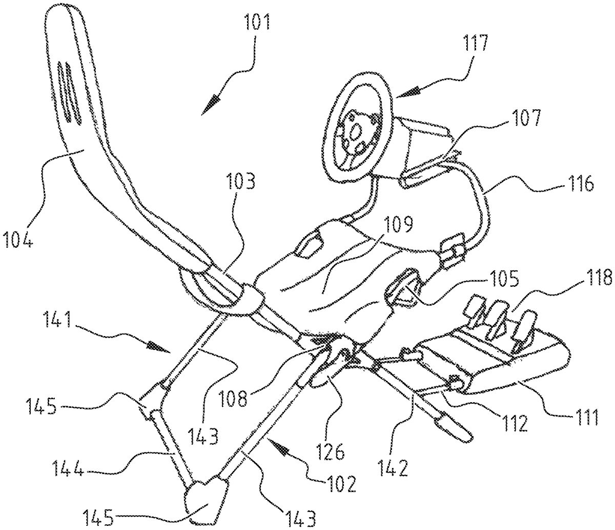
In the prior art seat1already briefly described above the relatively long tubular part3of frame2, which is covered with backrest4, and the shorter frame part5which carries the console7for a steering wheel or the joystick are connected pivotally to each other by means of hinge8. Known seat1is thereby movable between a collapsed position in which seat1can be stored (FIG.3) and a folded-out position of use (FIG.2). In this seat1the console7and pedal support11also take a pivotable form, respectively by interposing of simple brackets13with which console7is mounted on sub-frame16and by interposing of spacer12. In the known seat1the folded-out position of use is bounded by two straps10which are tensioned between frame parts3,5and in the folded-out position form two armrests. The folded-out position of use is determined by adjusting the length of these straps10. A seat101according to the invention, which is intended for playing video games, comprises a collapsible frame102which carries a seat surface109and a backrest104(FIG.4). Seat surface109and backrest104are in this embodiment formed integrally from a flexible material, for instance a fabric. In the shown embodiment frame102comprises a number of separate frame parts which are connected to each other with interposing of a hinge108. A first frame part103carries backrest104, while a second frame part105carries a separate sub-frame116with thereon a console107on which a racing steering wheel117is mounted in the shown embodiment. Instead of a steering wheel117, a joystick could also be mounted on console107of sub-frame116. In order to simplify getting in and out of the seat, sub-frame116can be connected to frame part105releasably on one side and pivotally on the other side, so that it can be released and folded away to the side. A forward-directed foot end of frame102carries a pivotable spacer112with a support111for a separate pedal set118. Steering wheel117(or optionally the joystick) and pedal set118are connected to a game computer (not shown here). Seat101can be placed ...
In the prior art seat1already briefly described above the relatively long tubular part3of frame2, which is covered with backrest4, and the shorter frame part5which carries the console7for a steering wheel or the joystick are connected pivotally to each other by means of hinge8. Known seat1is thereby movable between a collapsed position in which seat1can be stored (FIG.3) and a folded-out position of use (FIG.2). In this seat1the console7and pedal support11also take a pivotable form, respectively by interposing of simple brackets13with which console7is mounted on sub-frame16and by interposing of spacer12. In the known seat1the folded-out position of use is bounded by two straps10which are tensioned between frame parts3,5and in the folded-out position form two armrests. The folded-out position of use is determined by adjusting the length of these straps10.
A seat101according to the invention, which is intended for playing video games, comprises a collapsible frame102which carries a seat surface109and a backrest104(FIG.4). Seat surface109and backrest104are in this embodiment formed integrally from a flexible material, for instance a fabric. In the shown embodiment frame102comprises a number of separate frame parts which are connected to each other with interposing of a hinge108. A first frame part103carries backrest104, while a second frame part105carries a separate sub-frame116with thereon a console107on which a racing steering wheel117is mounted in the shown embodiment. Instead of a steering wheel117, a joystick could also be mounted on console107of sub-frame116. In order to simplify getting in and out of the seat, sub-frame116can be connected to frame part105releasably on one side and pivotally on the other side, so that it can be released and folded away to the side.
A forward-directed foot end of frame102carries a pivotable spacer112with a support111for a separate pedal set118. Steering wheel117(or optionally the joystick) and pedal set118are connected to a game computer (not shown here). Seat101can be placed in front of a screen (not shown here either), after which a user can sit in seat101and can control the game using hands and feet via steering wheel117(or the joystick) and pedal set118.
According to an aspect of the present invention, the seat101shown inFIG.4is distinguished from the known seat1ofFIGS.1-3in that hinge108itself can be locked, whereby the frame parts can be fixated relative to each other without having to make use of tensioning straps. This considerably simplifies getting in and out.
Hinge108is for this purpose provided with locking means119. In the shown embodiment the locking means enable the frame parts to be fixated in different positions relative to each other, whereby seat101can be adjusted to players with various postures. The locking means can be force-locked, i.e. for instance operate according to the principle of friction, but this requires a (relatively great) force to act on the hinge under all conditions, which requires a heavy construction or requires a continuous supply of energy. In the shown example locking means119are therefore form-fitting; they operate according to the principle of mutually engaging parts.
In the shown embodiment hinge108comprises two hinge parts133,134which are rotatable relative to each other. Locking means119comprise here two locking parts120,121, particularly rotatable, which are displaceable relative to each other and are each connected to one of the hinge parts133,134. Each locking part120,121is provided with a circularly running toothing122,123. Locking parts120,121are movable between a first position shown with full lines inFIG.7, in which toothings122,123mutually engage and the locking parts120,121are thus blocked, and a second position shown with broken lines (wherein the reference numerals are provided with an accent), in which the toothings122,123′ are held at a mutual distance. In the second position the locking parts120,121′ and the hinge parts133,134′ connected thereto are rotatable relative to each other, whereby the relative position of the frame parts can be varied and reset.
Locking means119here comprise a securing member124with which locking parts120,121can be secured in their first position, so the locked position in which toothings122,123engage in each other. In the shown embodiment this securing member124comprises an eccentric125. Eccentric125forms part of a handle126which is pivotable about a shaft127. This shaft127is arranged on a stem128which protrudes outward from first locking part120through a central opening129in second locking part121. Eccentric125has a segment130with a relatively small radius R1and a segment131with relatively large radius R2.
When handle126is pivoted to a first position, in which it extends substantially parallel to second locking part121, segment131with relatively large radius R2is in contact with an outer surface132of second locking part121, whereby shaft127is situated further from this outer surface132and stem128is thus pulled into second locking part121on the opposite side. Toothings122,123are hereby urged into engagement with each other so that the two locking parts120,121are blocked relative to each other.
When frame102has to be placed in a different position, hinge parts133,134, and so with this also locking parts120,121, have to be rotated to a different relative position. Handle126is for this purpose pivoted through about 180° to a second position, in which it extends substantially parallel to second locking part121substantially on the other side of shaft127. In this position of handle126′ the segment130′ with relatively small radius R1is in contact with an outer surface132′ of second locking part121′. Shaft127is thereby situated closer to this outer surface132′ and stem128can thus extend on the opposite side outside second locking part121′. A distance D is hereby created between the two locking parts120,121′, whereby the toothings122,123′ disengage and locking parts120,121′ can be displaced, for instance rotated, relative to each other. In order to urge the locking parts120,121′ apart in this situation so that the displacement can be carried out unimpeded a spring133(only shown schematically) can be arranged therebetween.
Locking parts120,121or hinge parts133,134can otherwise also be provided with co-acting stop means (not shown here) for bounding the relative rotation.
In this way hinge parts133,134and the frame parts connected thereto can thus quickly and easily be placed in a desired relative position and be fixated in this position in reliable manner. The number of possible positions is here bounded only by the number of teeth of the toothings122,123. In the shown embodiment toothings122,123each have 60 teeth, whereby an angle between the frame parts can be adjusted in steps of 6°. Hinge parts133,134can otherwise also be provided with markings (not shown here) with which a number of preferred settings is indicated. The two hinges108on either side of frame102can thus be placed in the same position in simple manner.
When a less accurate adjustment is necessary, it is possible to suffice with a simpler locking mechanism.FIG.5shows schematically a hinge208which connects two frame parts203,205to each other. Hinge208comprises two hinge parts233,234which are connected rotatably to each other by means of a central pin228and opening229. In this embodiment a locking part220, which is connected to hinge part233, has only three recesses222A for setting the angle of the backrest, and an additional recess222B for fixating the frame in the collapsed position. The other locking part221, which is connected to hinge part234, is here provided with a single protrusion, for instance a spring-loaded pin223. By pulling pin223from one of the recesses222counter to the force of the spring (not shown) hinge208is unlocked and locking parts220,221can be rotated relative to each other until pin223is aligned with another recess222. Pin223can then be inserted into this recess222in order to block locking parts220,221relative to each other again. In this embodiment the frame parts203,205are otherwise mounted on the outer side of the corresponding hinge parts233,234and run over an axis defined by pin228and hole229.
Other locking mechanisms can also be envisaged, such as for instance in the form of a hinge with a ratchet function.
According to a main aspect of the invention, seat101is distinguished from the known seat1ofFIGS.1-3in that hinge108is embodied as structural component and consists of two load-bearing hinge parts or bodies133,134. Each load-bearing hinge body133,134here comprises a central part135,136which carries the toothing122,123of the corresponding locking part120,121. In the shown embodiment this central part135,136takes a cylindrical form. Each hinge body133,134further comprises two spacers, respectively137A,137B and138A,138B, which extend in substantially opposite direction from central part135,136. Central parts135,136and spacers137A,137B,138A,138B can be manufactured from the same material or from different materials. Materials which can be envisaged are steel, light metal and plastics, optionally fibre-reinforced. In the embodiment shown here each central part135,136is cast integrally with the corresponding spacers137A,137B,138A,138B from aluminium.
In the shown embodiment spacers137A,137B and138A,138B are in each case mounted on central part135,136staggered relative to each other, so that the frame parts come to lie adjacently of each other in the collapsed position (FIG.8). In order to still ensure an optimal transfer of forces between spacers137A,137B,138A,138B and central part135,136the spacers are in the shown embodiment provided with a substantially Y-shaped outer end, whereby a shore149A,149B,150A,150B is in each case formed. Each shore149,150runs from a position roughly on the central axis of the relevant spacer137,138to a position in the centre of the central part135,136, whereby shores149,150run slightly obliquely in top view (FIG.10). In order to create sufficient space here for these shores149,150when frame102is collapsed, the Y-shaped outer ends of spacers137A,137B,138A,138B are in the shown embodiment provided with a flattened inner surface—wherein only the inner surfaces151A,151B of spacers137A,137B are visible here. In other embodiments of the load-bearing hinge the spacers can also extend purely radially, as seen from the central axis of the hinge, so that they thus in each case lie pairwise in one line.
Each spacer137A,137B and138A,138B has here at its free outer end a mounting point, respectively139A,139B and140A,140B, with which a frame part can be mounted on the load-bearing hinge108. In the shown embodiment each mounting point139A,139B,140A,140B comprises a narrowed end part of the relevant spacer137A,137B,138A,138B, over which a tubular frame part can be placed. The diameter of the narrowed part is adapted to the inner diameter of the tubular frame part such that the frame part can slide thereover close-fittingly and is thus clamped fixedly to hinge108.
In the shown embodiment the outer ends of spacers137A,137B,138A,138B are further provided with means for securing the frame tubes placed thereover. Formed in each end part, which takes a hollow form, is a hole152A,152B,153A,153B in which a pressing member154A,154B,157is arranged (FIG.9). Each pressing member154A,154B,157is urged outward by a flexure spring155A,155B,156A,156B received in the hollow end part, and then engages in a recess or groove on the inner side of a tubular frame part. The frame parts are thus mounted on load-bearing hinge108firmly and without clearance, yet still in easily releasable manner. Spacers137,138all take a slightly curved form so that mounting points139,140at their free outer ends all lie in the same plane, which is defined by toothings122,123of locking parts120,121.
The tubular frame parts can otherwise also be manufactured from the same material or from different materials. Materials which can be envisaged are once again steel, light metal and (optionally fibre-reinforced) plastics.
Because hinge108is embodied as a load-bearing structure, and the frame parts can be mounted thereon, the frame parts can also take a smaller form than in the prior art seat1. While frame parts3,5of known seat1still extend on either side of hinge8, and hinge8thus in fact protrudes through frame parts3,5, this is different in seat101according to the invention. The frame parts are now as it were interrupted at the position of hinge108, whereby their height is almost halved.
As can be seen inFIG.11, frame102of seat101can be assembled by mounting frame parts103,105,141and142from four sides on the four spacers137A,137B,138A,138B of hinge108. Seat101comprises here two of such hinges108so that frame parts103,105,141,142, which are substantially U-shaped, are connected to each other in an X-shape on either side of seat101. After frame parts103,105,141,142have thus been connected to each other, backrest104can be arranged on first frame part103and seat surface109can be tensioned between the first and second frame part103,105. Backrest104and seat surface109are here in the shown embodiment formed integrally from textile material.
Because seat101according to the invention comprises four frame parts103,105,141,142rather than two frame parts3,5for the known seat1, it can be stored or packaged smaller in disassembled state.
In order to enable seat101to be packaged smaller still, frame parts103,105,141,142can themselves also be taken apart into smaller components. Each frame part can thus be constructed from three tubes which are connected to each other by means of two corner pieces into a U-shaped frame part. This can be seen inFIG.4for lower frame part141on the rear side of seat101, which is constructed from two tubes143which are mounted on hinges108, and a transverse tube144which extends parallel to a connecting line between hinges108. Tubes143,144are connected to each other by means of corner pieces145which also function as feet, which make seat101stable. Lower frame part142on the front side of seat101has a similar construction, while first frame part103and second frame part105in the shown embodiment also consist of tubes which are connected releasably to each other. In the case of first frame part103the transverse tube per se has a U-shape here, and each leg thereof is connected at the position of a bend146in first frame part103to another tube.
The option of assembling seat101from a number of relatively short tube parts which are connected into a stable whole by the load-bearing hinges108enables seat101to be stored or packaged and transported in a relatively small space. For seat101it is thus possible to suffice with a packaging147, the dimensions of which amount to about half of those of a packaging148for conventional seat1(FIG.12).
The invention thus provides a seat which provides an improved functionality and can furthermore be packaged smaller than the known seat. It should otherwise be noted that all the above described new features of the seat according to the invention can per se form essential components of the invention, which can be applied in different combinations. The load-bearing hinge as described here can thus also be applied without locking, in combination with a seat with a folded-out position which is determined by straps/armrests, while the locking of the hinge could on the other hand also be applied in a conventional seat with two different frame parts as shown inFIGS.1-3.
The scope of the invention is therefore defined solely by the following claims.
Claims
- A seat for video games, comprising: a collapsible frame which carries a seat surface and a backrest, wherein the frame comprises a first part carrying the backrest and a second part configured to carry a console for a steering wheel or joystick for controlling a video game, which parts are connected pivotally to each other by a hinge, wherein the hinge comprises a first load-bearing body on which the first frame part is mounted, and a second load-bearing body on which the second frame part is mounted, and each load-bearing hinge body has at least two points, lying substantially opposite each other, for mounting of the first or second frame part;a first locking part connected to a first hinge part;and a second locking part connected to a second hinge part, wherein the first hinge part is rotatable relative to the second hinge part and the locking parts, which are displaceable relative to each other, are each provided with a toothing.
- A seat according to claim 1, wherein the frame comprises at least four frame parts mounted on the hinge.
- A seat according to claim 1, wherein the first and second frame part each comprise a number of mutually connected tubular elements.
- A seat according to claim 3, wherein at least some of the frame parts each comprise three tubes which are assembled by two corner pieces into a substantially U-shaped frame part.
- A seat according to claim 1, wherein the hinge fixates the first and second frame parts in a desired position relative to each other.
- A seat according to claim 5, wherein the first and second frame parts are fixated in different positions.
- A seat according to claim 6, wherein the first locking part and the second locking part are form-fitting.
- A seat according to claim 6, further comprising a securing member, wherein the locking parts are movable between a first position in which they engage in each other and a second position in which they are displaceable relative to each other, wherein the securing member secures the displaceable locking parts in the first position.
- A seat according to claim 8, wherein the securing member comprises an eccentric.
- A seat according to claim 1, wherein one of the locking parts is integrated with the first load-bearing hinge body and the other locking part is integrated with the second load-bearing hinge body.
- A seat according to claim 1, wherein the toothing comprises a plurality of toothings running at least partially circularly and the locking parts are rotatable relative to each other.
- A seat according to claim 1, wherein the seat surface and/or the backrest are manufactured from a flexible material.
Disclaimer: Data collected from the USPTO and may be malformed, incomplete, and/or otherwise inaccurate.