U.S. Pat. No. 11,541,311
PROGRAM, ELECTRONIC DEVICE, AND METHOD FOR SIMULATING A JOYSTICK IN A VIRTUAL SPACE
AssigneeCYGAMES, INC.
Issue DateNovember 5, 2020
Illustrative Figure
Abstract
One or more embodiments of the invention is a program that is executed on an electronic device, the program causing the electronic device to execute: holding data points indicated by values on a first axis and values on a second axis, obtained on the basis of touch events; terminating the holding of a data point for which a predefined holding period has expired among the held data points; determining the slope of a regression line on the basis of the held data points; determining an amount of rotation by which the determined slope of the regression line is to be rotated, on the basis of a displacement direction of the set of the held data points; and determining an angle by which the user controls an object being operated in a virtual space, on the basis of the determined slope of the regression line and the determined amount of rotation.
Description
DESCRIPTION OF EMBODIMENTS An embodiment of the present invention will be described below with reference to the drawings. The same reference signs signify the same or corresponding parts throughout the drawings unless otherwise specifically mentioned, and there are cases where the vertical to horizontal scale is shown to be different from the real scale for convenience of description. Furthermore, there are cases where descriptions that are more detailed than necessary are omitted for convenience of description. For example, there are cases where detailed descriptions of matters that are already well known and repeated descriptions of substantially the same configurations are omitted. An electronic device10according to an embodiment of the present invention has installed therein a game application that presents a user with a virtual object disposed in a virtual space while causing the game to proceed. When the game application is executed, the electronic device10according to this embodiment provides a virtual controller (virtual controller) for controlling an object being operated, which is a virtual object being operated by the user in the virtual space, in response to an operation by the user. The virtual space is defined by the game application, and may be either a two-dimensional space or a three-dimensional space. For example, the virtual object is a character or an item disposed in the virtual space. For example, controlling the object being operated means controlling the character or the item disposed in the virtual space. For convenience of description, in this embodiment it is assumed that the electronic device10has the above-described game application installed therein; however, there is no limitation to the above-described game application. It suffices for the electronic device10to have installed therein a game application that can control an object being operated in response to an operation by a user. For example, instead of or in ...
DESCRIPTION OF EMBODIMENTS
An embodiment of the present invention will be described below with reference to the drawings. The same reference signs signify the same or corresponding parts throughout the drawings unless otherwise specifically mentioned, and there are cases where the vertical to horizontal scale is shown to be different from the real scale for convenience of description. Furthermore, there are cases where descriptions that are more detailed than necessary are omitted for convenience of description. For example, there are cases where detailed descriptions of matters that are already well known and repeated descriptions of substantially the same configurations are omitted.
An electronic device10according to an embodiment of the present invention has installed therein a game application that presents a user with a virtual object disposed in a virtual space while causing the game to proceed. When the game application is executed, the electronic device10according to this embodiment provides a virtual controller (virtual controller) for controlling an object being operated, which is a virtual object being operated by the user in the virtual space, in response to an operation by the user. The virtual space is defined by the game application, and may be either a two-dimensional space or a three-dimensional space. For example, the virtual object is a character or an item disposed in the virtual space. For example, controlling the object being operated means controlling the character or the item disposed in the virtual space.
For convenience of description, in this embodiment it is assumed that the electronic device10has the above-described game application installed therein; however, there is no limitation to the above-described game application. It suffices for the electronic device10to have installed therein a game application that can control an object being operated in response to an operation by a user. For example, instead of or in addition to the game application, the electronic device10may have installed therein an input support application or a simulation application that brings about an action of an object being operated in response to an operation by a user. The virtual controller provided by the electronic device10in this embodiment can be used for the type of user input requiring a direction and a magnitude. In the following description, the term “application” refers to application programs in general, and may refer to apps that are installed on a smartphone or a tablet.
FIG.1is a block diagram showing the hardware configuration of the electronic device10according to the embodiment of the present invention. The electronic device10includes a processor11, an input device12, a display device13, a storage device14, and a communication device15. These constituent devices are connected via a bus16. It is assumed that interfaces are interposed as needed between the bus16and the individual constituent devices. In this embodiment, the electronic device10is a smartphone. Alternatively, the electronic device10may be a terminal such as a computer equipped with a contact-type input device, like a tablet computer or a touchpad, as long as the terminal includes the configuration described above.
The processor11controls the overall operation of the electronic device10. For example, the processor11is a CPU. Alternatively, an electronic circuit such as an MPU may be used as the processor11. The processor11executes various kinds of processing by loading programs and data stored in the storage device14and executing the programs. In one example, the processor11is constituted of a plurality of processors.
The input device12is a user interface for accepting inputs to the electronic device10from the user; for example, the input device12is a touchscreen, a touchpad, a keyboard, or a mouse. The display device (display)13displays application screens, etc. to the user of the electronic device10under the control of the processor11. In this embodiment, since the electronic device10is a smartphone, the electronic device10includes a touchscreen17as the input device12, and the touchscreen17also functions as the display device13; that is, the input device12and the display device13have an integrated structure. Although the touchscreen17in this embodiment is a projection-type capacitive touchscreen, a device having an equivalent function, if any, may be adopted.
The storage device14is a storage device included in an ordinary smartphone, including a RAM, which is a volatile memory, and a ROM, which is a non-volatile memory. The storage device14may also include an external memory. The storage device14stores various kinds of programs, including a game application. For example, the storage unit14stores an operating system (OS), middleware, application programs, various kinds of data that may be referred to when these programs are executed, etc.
In one example, the storage device14includes a main storage device and an auxiliary storage device. The main storage device is a volatile storage medium that allows high-speed reading and writing of information, and is used as a storage area and a work area when the processor11processes information. The auxiliary storage device stores various programs and data that are used by the processor11when the individual programs are executed. The auxiliary storage device is, for example, a hard disk device; however, the auxiliary storage device may be any type of non-volatile storage or non-volatile memory, which may be of the removable type, that is capable of storing information.
The communication device15sends data to and receives data from other computers, such as a server, via a network. For example, the communication device15performs wireless communication, such as mobile communication or wireless LAN communication, to connect to the network2. In one example, the electronic device10downloads a program from a server by means of the communication device15and stores the program in the storage device14. Alternatively, the communication device15may perform known wired communication. In the case where data is neither sent to nor received from other computers, the electronic device10need not include the communication device15.
FIG.2is a functional block diagram of the electronic device10according to the embodiment of the present invention. The electronic device10includes an input unit21, a display unit22, and a control unit23. The control unit23includes an angle determination unit24, a state determination unit25, and an application unit26. In this embodiment, these functions are realized by the processor11executing a program. For example, the program that is executed is a program stored in the storage device14or received via the communication device15. Since various kinds of functions are realized by loading a program, as described above, a portion or the entirety of one part (function) may be provided in another part. Alternatively, these functions may be realized by means of hardware by configuring electronic circuits or the like for realizing the individual functions in part or in entirety.
The input unit21is configured by using the input device12, and accepts inputs to the electronic device10from the user. In this embodiment, the input unit21accepts a touch operation performed on the touchscreen17by the user and generates touch events, for which a touch detection function generally provided in a smartphone having the touchscreen17can be used.
The display unit22displays a game application screen on the display device13so as to display a screen in accordance with user operations.
The control unit23realizes a virtual controller. In this embodiment, an architecture having a three-layer structure is adopted for the control unit23, and the angle determination unit24, the state determination unit25, and the application unit26correspond to the individual layers. For example, the control unit23is realized by the processor11executing a program suite constituted of programs corresponding to the individual layers.
The role of the angle determination unit24in the virtual controller realized by the control unit23corresponds to a sensor IC chip inside the controller in the case of a physical controller. The angle determination unit24determines an angle for controlling an object being operated by the user in the virtual space by mainly using touch events generated by a touch operation on the touchscreen17by the user, and forwards the angle to the state determination unit25.
The role of the state determination unit25corresponds to the entire controller that is operated in the case of a physical controller. The state determination unit25determines a vector (angle and magnitude) corresponding to the touch operation performed on the touchscreen17by the user by mainly using the angle forwarded from the angle determination unit24.
The application unit26corresponds to a specific game application that implements actions, etc. in a game. In this game application, similarly to game applications in general, a frame rate is defined, and for example, the main loop of a main program is executed per period corresponding to the frame rate. Generally, the frame rate is 30 fps (frames per second) or 60 fps.
The angle determination unit24determines an angle that is required when the user controls an object being operated in the virtual space. In one preferred example, the angle determination unit24is a mathematical function library for calculating an angle in real time, and is a software module implementing a statistical processing algorithm for calculating an angle from a sequence of touch events during a short period. The sequence of touch events corresponds to finger motion on the touchscreen17.
The storage device14includes a data point buffer. The data point buffer is a buffer that enables the angle determination unit24to hold data points obtained on the basis of touch events and indicated by values on a first axis and values on a second axis.
The angle determination unit holds, in the data point buffer, data points obtained on the basis of touch events generated by user operations on the touchscreen17and indicated by values on the first axis and values on the second axis. Here, a touch event occurs when the user places a finger in contact with the touchscreen17(touchstart), when the user moves the finger while keeping the finger in contact with the touchscreen (touchmove), when the user removes the finger from the touchscreen17(touchend), etc. The angle determination unit24obtains a touch event when a touch event occurs. When obtaining a touch event, the angle determination unit24obtains a set of numerical values (x, y) consisting of two variables and corresponding to a position at which the electrostatic capacitance on the touchscreen17has changed, and also obtains time t at which (x, y) was obtained, and stores a set of numerical values (x, y, t) consisting of three variables in the data point buffer. The data of the set of numerical values consisting of two variables is obtained by the angle determination unit24in association with a touch event, and corresponds to data points indicated by values on a value on the first axis and a value on the second axis. t is a value representing a data point obtaining time, which is the time at which (x, y) was obtained, and is stored in the data point buffer in association with (x, y), as described above. In one example, t is an integer value called the UNIX (registered trademark) time or a character sequence such as “2017/07/14 15:48:43.444”. Hereinafter, unless otherwise specifically mentioned, the holding (or termination of holding) of a data point by the angle determination unit24includes the holding (or termination of holding) of a data point obtaining time t associated with the data point.
In this embodiment, for convenience of description, the first axis and the second axis are defined as follows.FIG.3is an illustration showing coordinate axes consisting of the first axis and the second axis in this embodiment. The first axis is an axis indicating the widthwise direction of the directions substantially parallel to the directions in which the sensors of the touchscreen17are arrayed; i.e., the first axis is a horizontal axis (x axis) substantially parallel to the shorter sides of the touchscreen17. The second axis is an axis perpendicular to the first axis and indicating the lengthwise direction of the directions substantially parallel to the directions in which the sensors of the touchscreen17are arrayed; i.e., the second axis is a vertical axis (y axis) substantially parallel to the longer sides of the touchscreen17. As described above, the first axis and the second axis are substantially parallel to the directions in which the sensors of the touchscreen17are arrayed, and a position on the touchscreen17is expressed in the form of coordinates (x, y) along the two axes. Thus, in this embodiment, the coordinates (x, y) of a data point correspond to a position on the touchscreen17. In this embodiment, the angle determination unit24holds the coordinates (x, y) as a data point in the data point buffer. The coordinate setting shown inFIG.3is just an example, and coordinates may be set differently from the above example depending on the sensor array of the touchscreen17or the program implemented by the electronic device10. The sensors are, for example, electrodes.
FIG.4is an illustration for explaining an example of an angle determined by the angle determination unit24and a direction corresponding to the angle in the case where coordinate axes are defined as shown inFIG.3. An angle31in the first quadrant corresponds to a direction32, an angle33in the second quadrant corresponds to a direction34, and an angle35in the fourth quadrant corresponds to a direction36. Here, although the direction34and the direction36have the same slope, since the direction34and the direction36are opposite to each other, it is possible to confirm that the angle33and the angle35differ by 180 degrees.
The angle determination unit24terminates the holding of a data point for which a predefined holding period has expired among the data points held in the data point buffer. For example, when terminating the holding of a data point, the angle determination unit24may delete the data, invalidate the data, or delete the data, as appropriate, by associating a flag indicating that the holding has been terminated with the data. The angle determination unit24, defines a variable D specifying, in milliseconds, the life of the data points stored in the data point buffer. The period specified by the variable D corresponds to the predefined holding period. However, the value of the variable D is not limited to milliseconds.
For example, after storing one data point in the data point buffer, the angle determination unit24monitors the time elapsed since the storage of the data point and continuously compares the time elapsed with the variable D. When the monitored time elapsed for the data point exceeds the variable D, the angle determination unit24terminates the holding of the data point in the data point buffer. In this manner, the angle determination unit24manages the life of every data point held in the data point buffer. At this time, the angle determination unit24can calculate the elapsed time by using the data point obtaining time t. It is assumed that the case where it is determined that the time elapsed exceeds the variable D may mean the case where it is determined that the time elapsed is greater than or equal to the variable D. Furthermore, the unit of the time elapsed for a data point, managed by the angle determination unit24, should preferably be the same as that of the variable D.
For example, when 165 is set in the variable D, the angle determination unit24holds a data point stored in the data point buffer for 165 milliseconds, and after 165 milliseconds has elapsed, terminates the holding of the data point in the data point buffer.
The angle determination unit24periodically determines whether or not it is possible to calculate an angle. In the case where it is possible to calculate an angle, the angle determination unit24calculates an angle indicated by the set of data points held in the data point buffer by using the data points, and determines the angle as an angle by which the user controls the object being operated in the virtual space. By obtaining the angle indicated by the set of data points, as described above, the angle determination unit24can obtain an angle of the direction intended by the user who has performed a touch operation on the touchscreen17.
The angle determination unit24outputs the determined angle to the state determination unit25. When outputting the determined angle to the state determination unit25, for example, the angle determination unit24outputs the determined angle together with information indicating an angle event. Instead of direct output to the state determination unit25, the angle determination unit24may store the determined angle and the information indicating an angle event in a memory area in the storage unit14referred to by the state determination unit25.
When the obtained touch event is touchstart, the angle determination unit24outputs a start event to the state determination unit25, and does not calculate an angle. When the obtained touch event is touchend, the angle determination unit24outputs a stop event to the state determination unit25, and does not calculate an angle.
The angle determination unit24defines a variable B, and calculates and determines an angle by using the data points held in the data point buffer in the case where the number of the data points is greater than or equal to the value of the variable B. In the case where the number of the data points held in the data point buffer is less than the value of the variable B, in which case it is not possible to calculate an angle indicated by the set of data points with at least a certain level of accuracy, the angle determination unit24outputs a keep event to the state determination unit25, and does not calculate an angle. Since it is generally preferable that three or more data points are available when obtaining the slope of a regression line, the variable B should preferably be set to be 3 or greater. In this embodiment, the variable B is set to be 3.
The angle determination unit24defines a variable I specifying, in milliseconds, the time interval for determining whether or not the angle determination unit24can calculate an angle. In the case where the situation where the angle determination unit24cannot calculate an angle continues, like a situation where touch events continuously occur, the interval serves as a time interval for the angle determination unit24to calculate an angle. However, the value of the variable I is not limited to milliseconds.
The angle determination unit24determines an angle per predefined processing period by determining whether or not it is possible to calculate an angle per predefined processing period, as described above. In one preferred example, the predefined processing period is a period corresponding to the frame rate for executing the game. In the case where the frame rate is 30 fps (30 Hz), the variable I is set to be 33. When 33 is set in the variable1, the angle determination unit24determines whether or not it is possible to calculate an angle every 33 milliseconds. In the case where it is possible to calculate an angle, the angle determination unit24determines a calculated angle and outputs the determined angle together with an angle event to the state determination unit25. In the case where it is not possible to calculate an angle, the angle determination unit24outputs one of a start event, a stop event, and a keep event to the state determination unit25. The angle event may include information indicating an angle, and in this case, the angle determination unit24outputs an angle event to the state determination unit25in the case where it is possible to calculate an angle.
In calculating an angle indicated by the set of data points held in the data point buffer, the angle determination unit24determines the slope of a regression line on the basis of the data points held in the data point buffer. Here, the number of data points referred to by the angle determination unit24is greater than or equal to 3. In determining the slope of a regression line, the angle determination unit24determines one of the x axis and the y axis as the axis of an independent variable on the basis of the amount of displacement in the values on the x axis and the amount of displacement in the values on the y axis in the data points held in the data point buffer. At the same time, the angle determination unit24determines the other axis as the axis of a dependent variable.
In this embodiment, the angle determination unit24calculates the slope of a regression line by using the method of least squares. The method of obtaining the slope of a regression line by using the method of least squares is known; in this method, the degree of correlation between an independent variable and a dependent variable is obtained in the form of the slope. The method of least squares is generally applied by considering the x axis as the axis of an independent variable and the y axis as the axis of a dependent variable. However, in the case where the value on the x axis is fixed and only the value on the y axis changes, the dependent variable has no dependency on the independent variable. Furthermore, in the case where a slope along the y axis is determined, the determined slope sometimes changes from a large negative value to a large positive value across the y axis, which makes it difficult to stably find the slope. Thus, the angle determination unit24determines which of the value on the x axis and the value on the y axis is suitable as an independent variable, and determines the slope of a regression line by using the method of least squares on the basis of the axis of the independent variable and the axis of the dependent variable thus determined.
The angle determination unit24determines the slope a of a regression line y=ax+b when the axis of the independent variable is the x axis, and determines the slope c of a regression line x=cy+d when the axis of the independent variable is the y axis. Specifically, the angle determination unit24obtains the slope of a regression line through (a) to (e) below.
(a) The angle determination unit24calculates (determines) the average of the independent variable and the average of the dependent variable in the data points held in the data point buffer.
(b) By using the averages calculated in (a), the angle determination unit24calculates (determines) the deviation of the independent variable and the deviation of the dependent variable in the data points held in the data point buffer.
(c) By using the deviation of the independent variable, determined in (b), the angle determination unit24, calculates (determines) the variance of the independent variable in the data points held in the data point buffer.
(d) The angle determination unit24, by using the deviation of the independent variable and the deviation of the independent variable, determined in (b), calculates (determines) the covariance in the data points held in the data point buffer.
(e) The angle determination unit24calculates (determines) the slope of the regression line by dividing the covariance, determined in (d), by the variance of the independent variable, determined in (c).
In one example, the angle determination unit24determines one of the x axis and the y axis as the axis of the independent variable and determines the other axis as the axis of the dependent variable on the basis of the difference between the maximum value and the minimum value of the values on the x axis and the difference between the maximum value and the minimum value of the values on the y axis in the data points held in the data point buffer. Preferably, the angle determination unit24determines one of the x axis and the y axis as the axis of the independent variable and determines the other axis as the axis of the dependent variable on the basis of the difference between the maximum value and the minimum value of the values on the x axis, the difference being weighted by using a weight coefficient, and the difference between the maximum value and the minimum value of the values on the y axis in the data points held in the data point buffer.
The angle determination unit24calculates (determines) the slope of a regression line by using the method of least squares, as described above. Preferably, the calculation of the slope of a regression line by the angle determination unit24means the calculation of the angle of the slope of a regression line by the angle determination unit24. Here, since the calculated slope of a regression line does not have a positive or negative direction, when calculating the slope of a regression line by using the method of least squares, the angle determination unit24calculates the slope, for example, within the range of 0 to 90 degrees and 270 to 360 degrees. Thus, for example, the slope of a regression line is calculated to be 45 degrees, whether the angle indicated by the set of data points is 45 degrees or 225 degrees. Thus, after determining the slope of a regression line, on the basis of the displacement direction of the set of data points held in the data point buffer, the angle determination unit24determines the amount of rotation by which the determined slope of the regression line is to be rotated. Specifically, after determining the slope of a regression line, when determining an angle by which the user controls the object being controlled, the angle determination unit24determines an amount of rotation indicating whether or not (the angle of) the determined slope of the regression line is to be rotated by 180 degrees. Here, the displacement direction of the set of data points indicates a direction in which the data points become displaced with time, and corresponds, for example, to a rough direction in which the user moves a finger on the touchscreen17.
In one example, the angle determination unit24determines the amount of rotation on the basis of the displacement direction of data points temporally succeeding and following each other among the data points held in the data point buffer. Preferably, the angle determination unit24determines the amount of rotation by comparing the number of positive differences and the number of negative differences between the values temporally succeeding and following each other on the axis of the determined independent variable in the data points held in the data point buffer. The amount of rotation that is determined is an amount of rotation indicating whether or not the determined slope of the regression line is to be rotated by 180 degrees.
The angle determination unit24stores data points so as to sequentially hold the data points in order from data points stored earlier in the data point buffer. Alternatively, when storing data points in the data point buffer, the angle determination unit24stores identification information that enables identification of the order of storage in association with the data points. As described above, the angle determination unit24holds data points in the data point buffer in such a manner that the order of storage can be identified, i.e., in such a manner that the temporal order of the stored data points can be identified. At this time, the angle determination unit24can use the values of data point obtaining times t.
The angle determination unit24calculates an angle indicated by the set of data points on the basis of the determined slope of the regression line and the determined amount of rotation, and determines the angle as an angle by which the user controls the object being operated in the virtual space.
In this embodiment, the determination of the slope of a regression line, the determination of an amount of rotation, and the determination of an angle, performed by the angle determination unit24described above, are realized by using an aop(x, y) function expressed in Eq. (1). The function aop(x, y) calculates an angle in the form of a real value in the range of 0 to 360 degrees. It is assumed that the data point buffer holds n data points P(x, y) when the function aop(x, y) calculates an angle. Furthermore, the value on the x axis and the value on the y axis of each of the n data points Pk(k=1 to n) are expressed by Pk(xk, yk), and it is assumed that the order of storage, in order from earlier storage, is P1(x1, y1), P2(x2, y2), . . . , Pn(xn, yn).
aop(x,y)={180atan(∑i=1n(xi-x_)(yi-y_)∑i=1n(xi-x_)2)π,⫬rotate(x,y)⋀⫬left(x)-180atan(∑i=1n(xi-x_)(yi-y_)∑i=1n(yi-y_)2)π+90,rotate(x,y)⋀⫬down(y)-180atan(∑i=1n(xi-x_)(yi-y_)∑i=1n(yi-y_)2)π+270,rotate(x,y)⋀down(y)180atan(∑i=1n(xi-x_)(yi-y_)∑i=1n(xi-x_)2)π+180,⫬rotate(x,y)⋀left(x)(1)
For the purpose of case classification, the function aop(x, y) uses a function rotate(x, y), a function left(x), and a function down(y). First, the function aop(x, y) determines either one of e and y as an independent variable by using the function rotate(x, y).
The function rotate(x, y) is defined by Eq. (2).
rotate(x,y)=w·(max(x)−min(x))0}|>|{x′|x′i0}|<|{y′|y′iΔy. Thus, the function rotate(x, y) does not satisfy the inequality and thus returns a false value.
Then, the function aop(x, y) calculates the differences (x42−x41, x43−x42, . . . x46−x45) between values temporally succeeding and following each other by using the function left(x). According toFIG.5, all the differences are positive. Thus, the function left(x) does not satisfy the inequality and thus returns a false value.
In the above example, the function rotate(x, y) is false, and the function left(x) is false. Thus, the function aop(x, y) obtains a regression line81, shown inFIG.7, from the set40of data points, and calculates an angle91from the slope of the regression line81, as shown inFIG.8.
FIG.9is an illustration showing an example of the data points held in the data point buffer at time t2. A set60of the data points held in the data point buffer consists of six data points P61to P66. The x coordinate values and the y coordinate values of P61, P62, . . . P66are respectively the same as the x coordinate values and the y coordinate values of P46, P45, . . . , P41, and it is assumed that the data points were stored in the order P61, P62, . . . , P66.
Similarly to the case of the example inFIG.5, the function rotate(x, y) does not satisfy the inequality and thus returns a false value. Then, the function aop(x, y) calculates the differences between values temporally succeeding and following each other by using the function left(x). According toFIG.9, all the differences are negative. Thus, the function left(x) satisfies the inequality and returns a true value.
In the above example, the function rotate(x, y) is false, and the function left(x) is true. Thus, the function aop(x, y) obtains a regression line82, shown inFIG.9, from the set60of data points, and calculates an angle92bobtained by adding 180 degrees to an angle92acalculated from the slope of the regression line82, as shown inFIG.10.
FIG.11is an illustration showing an example of the data points held in the data point buffer at time t3. A set70of the data points held in the data point buffer consists of six data points P71to P76. Furthermore, the x coordinate values and the y coordinate values of P71to P76are individually P71(x71, y71), P72(x72, y72), . . . P76(x76, y76), and it is assumed that the data points were stored in the data point buffer in the order P71, P72, . . . , P76.
It is understood fromFIG.12that the difference x75−x71(=Δx) between the x coordinate values of P75and P71corresponds to abs(max(x)−min(x)) and that the difference y76−y71(=Δy) between the y coordinate values of P76and P71corresponds to abs(max(y)−min(y)). According toFIG.11, 2×Δx<Δy. Thus, the function rotate(x, y) satisfies the inequality and thus returns a true value.
Then, the function aop(x, y) calculates the differences (y72−y71, y73−y72, . . . y76−y75) between values temporally succeeding and following each other by using the function down(y). According toFIG.11, all the differences are positive. Thus, the function down(y) does not satisfy the inequality and thus returns a false value.
In the above example, the function rotate(x, y) is true, and the function down(y) is false. Thus, the function aop(x, y) obtains a regression line83, shown inFIG.13, from the set70of data points, and calculates an angle93bobtained by subtracting an angle93acalculated from the slope of the regression line83from 90 degrees, as shown inFIG.13. Here, the angle93ashown inFIG.13is shown so as to correspond to the position in the case where the angle calculated from the slope of the regression line83in the case where y is considered as the independent variable and x is considered as the dependent variable is transformed back to the coordinates in which x is considered as the independent variable and y is considered as the dependent variable.
FIG.14is an illustration showing an example of the data points held in the data point buffer at time t4. Time t4is the time after an elapse of time Δt from time t1. A set40′ of the data points held in the data point buffer consists of eight data points P45to P52. Furthermore, the x coordinate values and the y coordinate values of P45to P52are respectively P45(x45, y45), P46(x46, y46) . . . P52(x52, y52), and it is assumed that the data points were stored in the order P45, P46, . . . , P52.
It is understood fromFIG.15that the difference x52−x45(=Δx) between the x coordinate values of P52and P45corresponds to abs(max(x)−min(x)) and that the difference y46−y52(=Δy) between the y coordinate values of P46and P52corresponds to abs(max(y)−min(y)). According toFIG.14, 2×Δx<Δy. Thus, the function rotate(x, y) satisfies the inequality and thus returns a true value.
Then, the function aop(x, y) calculates the differences (y46−y45, y47−y46, . . . y52−y51) between values temporally succeeding and following each other by using the function down(y). According toFIG.14, all the differences except y46−y45are negative. Thus, the function down(y) satisfies the inequality and thus returns a true value.
In the above example, the function rotate(x, y) is true, and the function down(y) is true. Thus, the function aop(x, y) obtains a regression line84, shown inFIG.16, from the set40′ of data points, and calculates an angle94cobtained by adding 180 degrees to an angle94bcalculated by subtracting an angle94acalculated from the slope of the regression line84from 90 degrees, as shown inFIG.17.
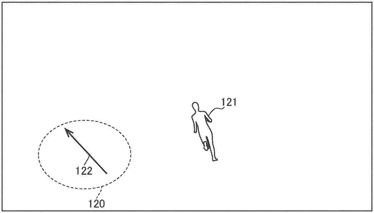
FIG.18is an illustration showing how the electronic device10according to the embodiment of the present invention controls a virtual character121on the basis of a set120of data points.FIG.18shows the set120of data points visualizing data points corresponding to touch events generated by a user operation on the touchscreen17. The electronic device10controls motion, such as walking, running, and switching direction, of the virtual character121, which is the object being operated, on the basis of the angle122indicated by the set120of data points.
FIG.19is a flowchart of information processing by the angle determination unit24, according to the embodiment of the present invention. This flowchart starts when a touch event is generated and the angle determination unit24obtains a data point from the touch event.
In step101, the angle determination unit24stores the obtained data point in the data point buffer. At this time, the angle determination unit24associates, with the data point being stored, T indicating the time, in milliseconds, elapsed after the storage thereof and D indicating the period (holding life), in milliseconds, for which the data point can be stored in the data point buffer.
Then, in step102, the angle determination unit24outputs a start event to the state determination unit25.
Then, in step103, the angle determination unit24determines whether or not a touch event has been generated. Step103is executed after I ms from the start of the flowchart. The flowchart proceeds to step104in the case where a touch event has been generated, and the flowchart proceeds to step106in the case where no touch event has been generated.
In step104, the angle determination unit24determines whether or not the generated touch event is touchend. The flowchart is terminated in the case where the obtained touch event is touchend. The flowchart proceeds to step105in the case where the obtained touch event is not touchend.
In step105, the angle determination unit24obtains a data point from the generated touch event, and stores the data point in the data point buffer. At this time, the angle determination unit24associates, with the data point being stored, T indicating, in milliseconds the time elapsed after the storage thereof and D indicating, in milliseconds, the period for which the data point can be stored in the data point buffer.
Then, in step106, the angle determination unit24terminates the holding of data points for which the elapsed period T is greater than or equal to the variable D among the data points held in the data point buffer. The angle determination unit24compares the elapsed time T with the variable D for each of the data points stored in the data point buffer, and terminates the holding of each data point for which the elapsed time is greater than or equal to the variable D.
Then, in step107, the angle determination unit24determines whether or not the number n of the data points held in the data point buffer is greater than or equal to the value of the variable B. The flowchart proceeds to step108in the case where the number n is greater than or equal to the variable B, and the flowchart proceeds to step113in the case where the number n is less than the variable B.
In step108, the angle determination unit24determines one of the x axis and the y axis as the axis of the independent variable on the basis of the amount of displacement of the values on the x axis and the amount of displacement of the values on the y axis in the data points held in the data point buffer. At the same time, the angle determination unit24determines the other axis as the axis of the dependent variable.
Then, in step109, in the case where the x axis is determined as the axis of the independent variable in step108, the angle determination unit24determines the angle of the slope of a regression line by calculating the angle of the slope by using Eq. (5). In one example, when calculating the angle of the slope by using Eq. (5), the angle determination unit24calculates the angle within the range of 0 to 90 degrees and 270 to 360 degrees. In the case where the y axis is determined as the axis of the independent variable in step108, the angle determination unit24calculates the angle of the slope by using Eq. (6), and subtracts the calculated angle from 90 degrees, thereby determining the angle of the slope of a regression line. In one example, when calculating the angle of the slope by using E. (6), the angle determination unit24calculates the angle within the range of 0 to 90 degrees and 270 to 360 degrees.
Then, in step110, the angle determination unit24determines an amount of rotation indicating whether or not the determined slope of the regression line is to be rotated by 180 degrees on the basis of the displacement direction of the set of data points held in the data point buffer. In one example, in the case where the x axis is determined as the axis of the independent variable in step108, the angle determination unit24calculates the individual differences between values temporally succeeding and following each other on the x axis. The angle determination unit24determines the amount of rotation to be 180 degrees when the number of negative calculated differences is greater than the number of positive calculated differences, and determines the amount of rotation to be 0 degrees when the former is less than the latter. In one example, in the case where the y axis is determined as the axis of the independent variable in step108, the angle determination unit24calculates the individual differences between values temporally succeeding and following each other on the y axis. The angle determination unit24determines the amount of rotation to be 180 degrees when the number of negative calculated differences is greater than the number of positive calculated differences, and determines the amount of rotation to be 0 degrees when the former is less than the latter.
Then, in step111, the angle determination unit24determines an angle on the basis of the determined slope of the regression line and the determined amount of rotation. Specifically, the angle determination unit24determines an angle by adding the determined amount of rotation to the angle corresponding to the determined slope of the regression line. For example, in the case where the amount of rotation is 0 degrees, the angle determined by the angle determination unit24is the angle corresponding to the determined slope of the regression line. The angle determination unit24outputs an angle event together with the determined angle to the state determination unit25, and proceeds to step112.
In the case where the number n is less than the variable B in step107, in step113, the angle determination unit24outputs a keep event to the state determination unit25, and proceeds to step112.
In step112, the flowchart returns to step103unless terminated, for example, due to the termination of the game application. The angle determination unit24executes the processing in steps103to112every I ms.
When the flowchart is terminated, the angle determination unit24deletes all the data points held in the data point buffer.
Next, main operations and advantages of the electronic device10according to the embodiment of the present invention will be described. This embodiment utilizes the characteristic of a projection-type electrostatic capacitive touchscreen, in which when the touchscreen17is swiped with a finger, six or more touch events are generated within an extremely short period, such as 100 ms. The system architecture of the software implemented by the electronic device10has a three-layer structure, in which the angle determination unit24, the state determination unit25, and the application unit26respectively correspond to the first layer, the second layer, and the third layer, where the third layer corresponds to the game application. The first layer calculates the swipe direction for a set of a plurality of generated touch events (a set of data points), in the form of a linear angle over 360 degrees. Since it is possible to use touch events generated within an extremely short period, it is possible for the first layer to continue to calculate an angle at high speed. Furthermore, by obtaining an angle indicated by a set of data points held in the data point buffer just for a predefined extremely short holding period (e.g., 165 ms), it is possible for the first layer to obtain an angle of the direction intended by the user who has performed a touch operation on the touchscreen17, without having to use reference points.
The electronic device10in this embodiment is designed on the basis of the concept that, however complex a user operation such as a swipe is, within an extremely short period, such as 100 ms, the user operation can be modeled on linear motion with constant velocity, and thus it is possible to predict and approximate an arbitrary nonlinear function (≈ human operation) by continuously calculating the values of the angle of motion with constant velocity.
The first layer calculates an angle at a relatively low frequency is the case where the value of the variable I is set to be relatively large. In this case, even immediately after the start of generation of touch events, for example, even immediately after the user has started an operation, the first layer calculates an angle in a state where a relatively large number of data points are held in the data point buffer. As described above, by setting the value of the variable I to be relatively large, it becomes possible to calculate an angle in which a user operation is reflected relatively loosely. Meanwhile, the first layer calculates an angle at a relatively high frequency in the case where the value of the variable I is set to be relatively small. In this case, immediately after the start of generation of touch events, for example, immediately after the user has started an operation, the first layer calculates an angle in a state where a relatively small number of data points are held in the data point buffer. As described above, by setting the value of the variable I to be relatively small, it becomes possible to calculate an angle in which a user operation is reflected relatively immediately.
The first layer calculates the slope of a regression line by using the method of least squares in calculating an angle indicated by a set of data points. In the case where x is fixed as the independent variable and y is fixed as the dependent variable, it is difficult to calculate the slope, for example, in the case where the slope is in a direction along the y axis. Thus, the first layer determines the independent variable and the dependent variable from the amount of displacement of the data points before calculating the slope of a regression line. With this configuration, it becomes possible for the first layer to stably calculate the slope of a regression line.
In calculating the angle indicated by the set of data points, the first layer determines an amount of rotation indicating whether or not the determined slope of the regression line is to be rotated by 180 degrees, on the basis of the displacement direction of the set of data points, corresponding to a rough direction in which the user moves a finger on the touchscreen17. By determining the amount of rotation, which cannot be ascertained from the slope of the regression line, calculated by using the method of least squares, it is possible to obtain an angle intended by the user who has performed a touch operation on the touchscreen17.
The first layer calculates an angle corresponding to the swipe direction for a set of data points per predefined processing period, for example, per period corresponding to the frame rate of the game application as the predefined processing period. The second layer determines a vector quantity (angle and magnitude) indicating the state of the slope of the virtual controller per predefined processing period by using continuously output angle information, and outputs the vector quantity to the game application. With this configuration, in this embodiment, it becomes possible to give an input to the game application on the basis of the angle calculated per predefined processing period. Furthermore, with this configuration, without requiring any layer to use past touched coordinates as reference points, it becomes possible to give an input on the basis of an accurate movement angle at high frequency at the frame rate calculated by the first layer. As described above, in this embodiment, the electronic device10calculates an angle without using the spatial concept of points, such as starts points (start coordinates) and end points (end coordinates), which has been used in the virtual controllers in the existing technology.
Furthermore, in this embodiment, as opposed to the virtual controller in the existing technology, i.e., the virtual controller that uses a vector obtained on the basis of the positional relationship between reference coordinates and current instruction coordinates, the concept of reference coordinates is not involved, which makes it possible to provide higher responsiveness compared with the virtual controller with which reference coordinates are defined. In particular, in the case of an operation for switching the direction of a virtual character or the like, even if the user performs an operation on the touchscreen in a direction considerably different from the direction before switching, since the concept that the current instruction coordinates approach the reference coordinates is not lacking, it is possible to switch the direction by quickly responding to the intent of the operation by the user, which is considerably advantageous. Furthermore, with the configuration described above, a user operating a smartphone is allowed to perform operations with one hand. This makes it possible to solve the problem that it is necessary for a user to be constantly aware of reference coordinates when performing operations with the virtual joystick in the existing technology and thus there are cases where it is difficult to perform operations with one hand. As described above, in this embodiment, a virtual controller that enables quicker and more intuitive operation is realized.
Furthermore, in this embodiment, as opposed to the virtual controller in the existing technology, since input is not based on the movement distance of a finger from reference coordinates, it becomes possible for the electronic device10to realize operations intended by the user via operations with smaller amounts of movement of a finger. Thus, as compared with the existing technology, implementation with a smaller implementation area becomes possible. For example, it becomes possible to realize the same operability irrespective of the size of the touchscreen17.
Furthermore, since the technology of the virtual controller provided by the electronic device10in this embodiment is based on a mathematical model of angle recognition from a swipe operation, the technology is applicable to a wide variety of genres, such as movement in directions over 360 degrees, acceleration and deceleration, and input of commands in a combat game or the like.
The operations and advantages described above also apply similarly to other embodiments and other examples unless otherwise specifically mentioned.
Another embodiment of the present invention may be a program for realizing the functions or the information processing shown in the flowchart in the above-described embodiment of the present invention, or a computer-readable storage medium storing the program. Furthermore, another embodiment of the present invention may be a method for realizing the functions or the information processing shown in the flowchart in the above-described embodiment of the present invention. Furthermore, another embodiment of the present invention may be a server that is capable of providing a computer with a program for realizing the functions or the information processing shown in the flowchart in the above-described embodiment of the present invention. Furthermore, another embodiment of the present invention may be a virtual machine for realizing the functions or the information processing shown in the flowchart in the above-described embodiment of the present invention.
Now, modifications of the embodiments of the present invention will be described. The modifications described below can be combined as appropriate and applied to any embodiment of the present invention as long as no inconsistency arises.
In one modification, the electronic device10has installed there in a game application that disposes a virtual object in a virtual space and that presents a user with a game image photographed by a virtual camera disposed in the virtual space while causing the game to proceed. When the game application is executed, the electronic device10displays, on the touchscreen17, a game image obtained by photographing the virtual object, etc. disposed in the virtual space by means of the virtual camera disposed in the virtual space, and controls the virtual camera in accordance with user operations. As described above, when the game application is executed, the electronic device10provides a virtual controller for controlling the virtual camera, which is an object being operated, in accordance with user operations. The control of the virtual camera refers to controlling the motion or the visual field region of the virtual camera disposed in the virtual space.
FIG.20is an illustration showing a virtual camera131disposed in the virtual space, which captures an image displayed by the electronic device10according to the embodiment of the present invention.FIG.20shows the position of the virtual camera131and a viewing direction132of the virtual camera132. The viewing direction132is defined in the form of a three-dimensional vector with the viewpoint set at the position of the virtual camera131. A visual field region is defined with a certain viewing angle from the virtual camera131into the viewing direction132, and a two-dimensional screen133, constituting a plane perpendicular to the viewing direction132, is defined in the visual field region. The virtual object in the virtual space is projected onto the two-dimensional screen133, whereby a two-dimensional image is formed.
In one modification, the input device12and the display device13have separate forms disposed at different positions. In this case, the input device12is a touchscreen or a device having a function equivalent to the function of a projection-type electrostatic capacitive touchscreen. It suffices for the display device13to be a device that displays an application screen, etc. to the user of the electronic device10under the control of the processor11. For example, the display device13is a liquid crystal display, a display using organic EL, or a plasma display.
In one modification, the angle determination unit24calculates the slope of a regression line by using a known method other than the method of least squares. In this case, the angle determination unit24does not determine an amount of rotation indicating whether or not the determined slope of the regression line is to be rotated by 180 degrees, and thus does not determine the axis of the independent variable and the axis of the dependent variable. For example, it is possible to use an algorithm such as the Kalman filter or particle filters.
In one modification, the angle determination unit24does not define the variable D, and does not terminate the holding of a data point for which it is determined that the predefined holding period has expired among the data points held in the data point buffer. In this case, the angle determination unit24determines an angle while referring to data points stored in a specific time band that is shifted per time defined by the variable I.
In one modification, the angle determination unit24does not define the variable V. In this case, the angle determination unit24calculates and determines an angle by using the function aop(x, y) irrespective of the value of the variance of the independent variable.
In one modification, the electronic device10is equipped with an acceleration sensor that is capable of determining the gravitational direction. The angle determination unit24determines a weight coefficient by using information obtained from the acceleration sensor. For example, in the case where the smartphone is held in portrait orientation and thus the y axis of the touchscreen17is the gravitational direction, the angle determination unit24determines w to be 2. Meanwhile, in the case where the smartphone is held in landscape orientation and thus the x axis of the touchscreen17is the gravitational direction, and the game engine provided in the game application does not perform transformation between vertical and horizontal coordinates, the angle determination unit24determines w to be a value less than 1, such as 0.5.
In one modification, when obtaining a touch event, the angle determination unit24obtains a set (x, y) of numerical values consisting of two variables, and stores the set (x, y) of numerical values consisting of the two variables in the data point buffer without associating a data point obtaining time t therewith. For example, the angle determination unit24can store information corresponding to a data point obtaining time t in a memory area or the like in the storage device14other than the data point buffer and can manage the information in association with data stored in the data point buffer.
The processing or operation described above may be modified freely as long as no inconsistency arises in the processing or operation, such as an inconsistency that a certain step utilizes data that may not yet be available in that step. Furthermore, the examples described above are examples for explaining the present invention, and the present invention is not limited to those examples. The present invention can be embodied in various forms as long as there is no departure from the gist thereof.
REFERENCE SIGNS LIST
10Electronic device11Processor12Input device13Display device14Storage device15Communication device16Bus17Touchscreen21Input unit22Display unit23Control unit24Angle determination unit25State determination unit26Application unit31,33,35Angle32,34,36Direction81,82,83,84Regression line91,92a,92b,93a,93b,94a,94b,94cAngle120Set121Virtual character122Angle131Virtual camera132Viewing direction133Two-dimensional screen
Claims
- A non-transitory computer readable medium storing a program that is executed on an electronic device equipped with a touchscreen, the program causing the electronic device to execute: holding data points indicated by values on a first axis and values on a second axis that are obtained based on touch events generated as a result of an operation on the touchscreen by a user to produce a plurality of held data points;terminating holding of a data point for which a predefined holding period has expired among the plurality of held data points;determining a slope of a regression line based on the plurality of held data points;determining an amount of rotation by which the slope of the regression line is to be rotated, based on a displacement direction of a set of the plurality of held data points;and determining an angle by which the user controls an object being operated in a virtual space, based on the slope of the regression line and the amount of rotation.
- The non-transitory computer readable medium according to claim 1, wherein determining the amount of rotation comprises determining an angle for controlling the object being operated, and wherein the amount of rotation indicates whether or not the slope of the regression line is to be rotated by 180 degrees is determined based on a displacement direction of a plurality of data points temporally succeeding and following each other among the plurality of held data points.
- The non-transitory computer readable medium according to claim 1, wherein the program causes the electronic device to further execute: determining one of the first axis and the second axis as an axis of an independent variable, and determining the other axis as an axis of a dependent variable based on an amount of displacement of the values on the first axis and an amount of displacement of the values on the second axis in the plurality of held data points, and wherein the slope of the regression line is determined further based on the axis of the independent variable and the axis of the dependent variable.
- The non-transitory computer readable medium according to claim 3, wherein the axis of the independent variable is determined based on a difference between a maximum value and a minimum value of the values on the first axis and a difference between a maximum value and a minimum value of the values on the second axis.
- The non-transitory computer readable medium according to claim 3, wherein the axis of the independent variable is determined by comparing a magnitude of a result of applying a weight to a difference between a maximum value and a minimum value of the values on the first axis and a magnitude of a difference between a maximum value and a minimum value of the values on the second axis.
- The non-transitory computer readable medium according to claim 1, wherein, in response to determining an angle by which the object being controlled is controlled, an amount of rotation indicating whether or not the slope of the regression line is to be rotated by 180 degrees is determined by comparing a number of positive values and a number of negative values among differences between values temporally succeeding and following each other on the axis of an independent variable in the plurality of held data points.
- The non-transitory computer readable medium according to claim 1, wherein determining the slope of the regression line comprises: determining an average of an independent variable and an average of an dependent variable in the plurality of held data points;determining, by using the average of the independent variable and the average of the dependent variable, a deviation of the independent variable and a deviation of the dependent variable in the plurality of held data points;determining, by using the deviation of the independent variable, a variance of the independent variable in the plurality of held data points;determining, by using the variance of the independent variable and a variance of the dependent variable, a covariance in the plurality of held data points;and determining the slope of the regression line by dividing the covariance by the variance of the independent variable.
- The non-transitory computer readable medium according to claim 7, wherein the first axis is an X axis indicating a widthwise direction of directions in which sensors of the touchscreen are arrayed, wherein the second axis is a Y axis indicating a lengthwise direction of the directions in which the sensors of the touchscreen are arrayed, which is perpendicular to the first axis, and wherein, in response to the axis of the independent variable being the second axis, the slope of the regression line is determined by subtracting, from 90 degrees, an angle corresponding to the slope of the regression line and by dividing the covariance by the variance of the independent variable.
- The non-transitory computer readable medium according to claim 1, wherein the first axis is an X axis indicating a widthwise direction of directions in which sensors of the touchscreen are arrayed, and the second axis is a Y axis indicating a lengthwise direction of the directions in which the sensors of the touchscreen are arrayed, which is perpendicular to the first axis.
- The non-transitory computer readable medium according to claim 1, wherein the angle is determined per predefined processing period.
- The non-transitory computer readable medium storing a program suite for a game that is executed on the electronic device equipped with the touchscreen, the program suite including a program according to claim 10, wherein the predefined processing period is a period corresponding to a frame rate for executing the game, wherein the program suite causing the execution of: determining an angle and a magnitude per the predefined processing period based on the angle that is determined per the predefined processing period;and controlling the object being controlled, which is displayed on the touchscreen, based on the angle and the magnitude that are determined per the predefined processing period.
- The non-transitory computer readable medium storing a program suite for a game that is executed on the electronic device equipped with the touchscreen, the program suite including a program according to claim 10, wherein the predefined processing period is a period corresponding to a frame rate for executing the game, wherein the program suite causing the execution of: determining an angle and a magnitude per the predefined processing period based on the angle that is determined per the predefined processing period;and controlling a virtual camera for photographing a game image, the virtual camera serving as the object being controlled, which is displayed on the touchscreen, based on the angle and the magnitude that are determined per the predefined processing period.
- An electronic device comprises: a touchscreen, wherein the electronic device further comprises: data points indicated by values on a first axis and values on a second axis that are obtained based on touch events generated as a result of an operation on the touchscreen by a user to produce a plurality of held data points, wherein the holding of a data point for which a predefined holding period has expired among the plurality of held data points is terminated;a slope of a regression line that is determined based on the plurality of held data points;an amount of rotation by which the slope of the regression line is to be rotated is determined based on a displacement direction of a set of the plurality of held data points;and an angle by which the user controls an object being operated in a virtual space is determined based on the slope of the regression line and the amount of rotation.
- A method that is executed on an electronic device equipped with a touchscreen, the method comprising: holding data points indicated by values on a first axis and values on a second axis that are obtained based on touch events generated as a result of an operation on the touchscreen by a user to produce a plurality of held data points;terminating holding of a data point for which a predefined holding period has expired among the plurality of held data points;determining a slope of a regression line based on the plurality of held data points;determining an amount of rotation by which the slope of the regression line is to be rotated, based on a displacement direction of a set of the plurality of held data points;and determining an angle by which the user controls an object being operated in a virtual space, based on the slope of the regression line and the amount of rotation.
Disclaimer: Data collected from the USPTO and may be malformed, incomplete, and/or otherwise inaccurate.