U.S. Pat. No. 11,511,202
PORTABLE FOLDING VIDEO GAME CHAIR
Issue DateMay 22, 2021
Illustrative Figure
Abstract
A portable folding video game chair may include a backrest frame, a seating frame, a collapsible sling chair, a steering wheel controller column, a steering wheel controller shaft, a pedal controller frame, and a quick release pedals controller support. The backrest frame and seating frame may be pivotally coupled to each other. The collapsible sling chair may be coupled to the backrest frame and seating frame. The steering wheel controller column may be pivotally coupled to the seating frame and also movably coupled to the steering wheel controller column. The pedal controller frame may be pivotally coupled to the backrest frame and/or to the steering wheel controller. The quick release pedals controller support may have a pedals controller support aperture, and the quick release pedals controller support may be movably coupled to pedal controller frame by inserting a first and second pedal controller rail through a pedals controller support aperture.
Description
DETAILED DESCRIPTION OF THE INVENTION The terminology used herein is for the purpose of describing particular embodiments only and is not intended to be limiting of the invention. As used herein, the term “and/or” includes any and all combinations of one or more of the associated listed items. As used herein, the singular forms “a,” “an,” and “the” are intended to include the plural forms as well as the singular forms, unless the context clearly indicates otherwise. It will be further understood that the terms “comprises” and/or “comprising,” when used in this specification, specify the presence of stated features, steps, operations, elements, and/or components, but do not preclude the presence or addition of one or more other features, steps, operations, elements, components, and/or groups thereof. Unless otherwise defined, all terms (including technical and scientific terms) used herein have the same meaning as commonly understood by one having ordinary skill in the art to which this invention belongs. It will be further understood that terms, such as those defined in commonly used dictionaries, should be interpreted as having a meaning that is consistent with their meaning in the context of the relevant art and the present disclosure and will not be interpreted in an idealized or overly formal sense unless expressly so defined herein. In describing the invention, it will be understood that a number of techniques and steps are disclosed. Each of these has individual benefit and each can also be used in conjunction with one or more, or in some cases all, of the other disclosed techniques. Accordingly, for the sake of clarity, this description will refrain from repeating every possible combination of the individual steps in an unnecessary fashion. Nevertheless, the specification and claims should be read with the understanding that such combinations are entirely within the scope ...
DETAILED DESCRIPTION OF THE INVENTION
The terminology used herein is for the purpose of describing particular embodiments only and is not intended to be limiting of the invention. As used herein, the term “and/or” includes any and all combinations of one or more of the associated listed items. As used herein, the singular forms “a,” “an,” and “the” are intended to include the plural forms as well as the singular forms, unless the context clearly indicates otherwise. It will be further understood that the terms “comprises” and/or “comprising,” when used in this specification, specify the presence of stated features, steps, operations, elements, and/or components, but do not preclude the presence or addition of one or more other features, steps, operations, elements, components, and/or groups thereof.
Unless otherwise defined, all terms (including technical and scientific terms) used herein have the same meaning as commonly understood by one having ordinary skill in the art to which this invention belongs. It will be further understood that terms, such as those defined in commonly used dictionaries, should be interpreted as having a meaning that is consistent with their meaning in the context of the relevant art and the present disclosure and will not be interpreted in an idealized or overly formal sense unless expressly so defined herein.
In describing the invention, it will be understood that a number of techniques and steps are disclosed. Each of these has individual benefit and each can also be used in conjunction with one or more, or in some cases all, of the other disclosed techniques. Accordingly, for the sake of clarity, this description will refrain from repeating every possible combination of the individual steps in an unnecessary fashion. Nevertheless, the specification and claims should be read with the understanding that such combinations are entirely within the scope of the invention and the claims.
For purposes of description herein, the terms “upper,” “lower,” “left,” “right,” “rear,” “front,” “side,” “vertical,” “horizontal,” and derivatives thereof shall relate to the invention as oriented inFIG. 1. However, one will understand that the invention may assume various alternative orientations and step sequences, except where expressly specified to the contrary. Therefore, the specific devices and processes illustrated in the attached drawings, and described in the following specification, are simply exemplary embodiments of the inventive concepts defined in the appended claims. Hence, specific dimensions and other physical characteristics relating to the embodiments disclosed herein are not to be considered as limiting, unless the claims expressly state otherwise.
Although the terms “first,” “second,” etc. are used herein to describe various elements, these elements should not be limited by these terms. These terms are only used to distinguish one element from another element. For example, the first element may be designated as the second element, and the second element may be likewise designated as the first element without departing from the scope of the invention.
As used in this application, the term “about” or “approximately” refers to a range of values within plus or minus 10% of the specified number. Additionally, as used in this application, the term “substantially” means that the actual value is within about 10% of the actual desired value, particularly within about 5% of the actual desired value and especially within about 1% of the actual desired value of any variable, element or limit set forth herein.
A new portable folding video game chair is discussed herein. In the following description, for purposes of explanation, numerous specific details are set forth in order to provide a thorough understanding of the present invention. It will be evident, however, to one skilled in the art that the present invention may be practiced without these specific details.
The present disclosure is to be considered as an exemplification of the invention and is not intended to limit the invention to the specific embodiments illustrated by the figures or description below.
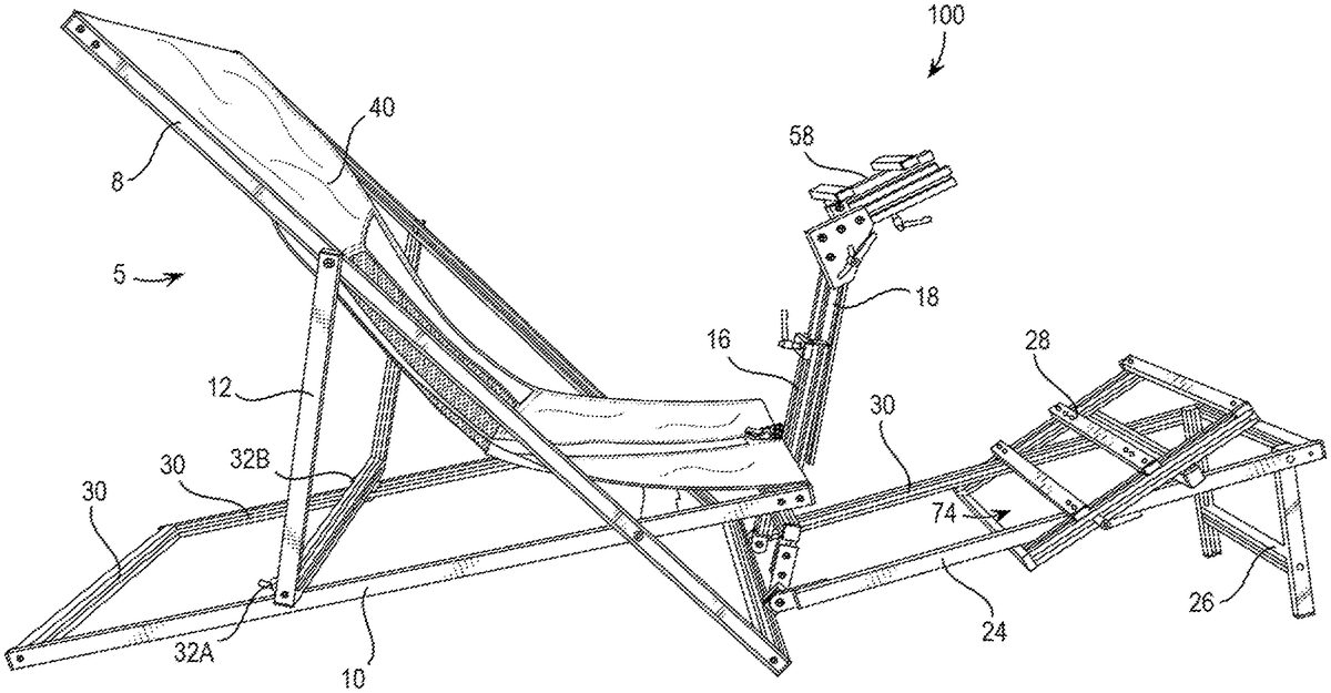
The present invention will now be described by example and through referencing the appended figures representing preferred and alternative embodiments.FIGS. 1, 2, 3, 6, 7, 16, and17illustrate examples of a portable folding video game chair (“the chair”)100according to various embodiments. In preferred embodiments, the chair100, is able to collapse very compactly into a storage configuration3(FIG. 6) suitable for facilitating shipment and storage. The chair100may be moved out of the storage configuration3and into one or more other configurations, such as an open wheel configuration5and a closed wheel configuration7, which may allow the chair100to support the body of a user205and preferably one or more games controller devices known in the art, such as a steering wheel controller201, a pedal controller202, a lever controller203, etc. The open wheel configuration5and closed wheel configuration7allow the chair100to provide the user205with selectable driver positions for different video games that incorporate one or more games controller devices201,202,203. Game controller devices201,202,203, are designed to work with video game platform including, but not limited to: Electronic video game consoles, and personal computers. The game controller devices201,202,203, are designed to work also with video game software including but not limited to: Open wheel car racing video game simulators, close wheel car racing video game simulators, and video game flight simulators. This makes the chair100suitable for use as a seat for car racing simulation as well for airplane fighting simulation and any other vehicle type simulation. The chair100described herein may be used to enhance the experience of any of the car racing and flight simulator video game software.
In some embodiments, the chair100may comprise a backrest frame8, a seating frame10, a collapsible sling chair40, a steering wheel controller column16, a steering wheel controller shaft18, a quick release steering wheel controller support58, a pedal controller frame24, and a quick release pedals controller support28. The backrest frame8may have a first front leg15, a second front leg17, a rear top crossbar11, and a front bottom crossbar13. The rear top crossbar11may couple an upper portion of the first front leg15to an upper portion of the second front leg17, and the front bottom crossbar13may couple a lower portion of the first front leg15to a lower portion of the second front leg17so that the first front leg15and second front leg17are substantially parallel to each other. The seating frame10may have a first rear leg23, a second rear leg25, a front top crossbar19, and a rear bottom crossbar21. The front top crossbar19may couple an upper portion of the first rear leg23to an upper portion of the second rear leg25, and the rear bottom crossbar21may couple a lower portion of the first rear leg23to a lower portion of the second rear leg25so that the first rear leg23and second rear leg25are parallel to each other. The first rear leg23may be pivotally coupled to the first front leg15and the second rear leg25may be pivotally coupled to the second front leg17. The collapsible sling chair40may be coupled to the front top crossbar19and to the rear top crossbar11. The steering wheel controller column16, having a pole47, may be coupled to the front bottom crossbar13. The steering wheel controller shaft18may have a steering wheel vertical adjuster shaft55that may be movably coupled to the pole47of the steering wheel controller column16. A quick release steering wheel controller support58having a quick release steering wheel controller horizontal adjuster59may be movably coupled to the steering wheel controller shaft18. The pedal controller frame24may have a first pedal controller rail63, a second pedal controller rail67, and a pedal controller frame crossbar71. The pedal controller frame crossbar71may couple an upper portion of the first pedal controller rail63to an upper portion of the second pedal controller rail67, a lower portion of the first pedal controller rail63may be coupled to the front bottom crossbar13, and a lower portion of the second pedal controller rail67may be coupled to the front bottom crossbar13. The quick release pedals controller support28may have a pedals controller support aperture74, and the quick release pedals controller support28is movably coupled to pedal controller frame24by inserting the first pedal controller rail63and second pedal controller rail67through the pedals controller support aperture74.
In preferred embodiments, the chair100may comprise a collapsible sling chair40which may be coupled to a backrest frame8and also to a seating frame10. The backrest frame8and seating frame10may be pivotally coupled to each other so that the chair100may be moved between a storage configuration3, an open wheel configuration5, and a closed wheel configuration7. The collapsible sling chair40may comprise a flexible material which may enable the shape of the collapsible sling chair40to change as the backrest frame8and seating frame10are moved relative to each other between the configurations3,5,7.
In some embodiments, the backrest frame8may comprise one or more structural elements which may include: at least one rear top crossbar11, at least one front bottom crossbar13, a first front leg15, and second front leg17, preferably forming a rectangular or trapezoidal shaped backrest frame8. In preferred embodiments, the at least one rear top crossbar11may be substantially parallel to the at least one front bottom crossbar13, and/or the first15and second17front legs may preferably be substantially parallel or optionally in angle in relation to each other. One or more of the elements11,13,15,17, of the backrest frame8may be made from or may comprise any substantially rigid material that may include various types of metal, such as, for example, aluminum, wood, carbon fiber, plastics or any other suitable materials known to those skilled in the art or a combination of those known materials. One or more of the rear top crossbar11, the front bottom crossbar13, the first front leg15, and the second front leg17, may be coupled together with any suitable coupling method, such as welding, adhesives, bonding, screwing, fastening, bending, being integrally formed or molded together, etc.
The seating frame10may comprise one or more structural elements which may include: at least one front top crossbar19, at least one rear bottom crossbar21, a first rear leg23, and second rear leg25, preferably forming a rectangular or trapezoidal shaped frame. In preferred embodiments, the at least one front top crossbar19may be substantially parallel to the at least one rear bottom crossbar21, and/or the first and second rear legs23and25may preferably be substantially parallel or optionally in angle in relation to each other. One or more of the elements19,21,23,25, of the seating frame10may be made from or may comprise any substantially rigid material that may include various types of metal, such as, for example, aluminum, wood, carbon fiber, plastics or any other suitable materials known to those skilled in the art or a combination of those known materials. In some embodiments the front top crossbar19, the rear bottom crossbar21, the first rear leg23, and the second rear leg25, may be coupled together with any suitable coupling method, such as welding, adhesives, bonding, screwing, fastening, bending, being integrally formed or molded together, etc.
In preferred embodiments, the backrest frame8and the seating frame10may be pivotally coupled together. In further preferred embodiments, the first rear leg23may be pivotally coupled to the first front leg15via a first hinge27and the second rear leg25may be pivotally coupled to the second front leg17via a second hinge29. When the chair100is not in the storage configuration3, such as by being in an open wheel configuration5or closed wheel configuration7, the hinges27and29may enable the backrest frame8and the seating frame10to generally form a crisscrossed structure. Hinges27and29may comprise any pivotal coupling method, such as nut and bolt type fasteners, rivets, etc.
The chair100may comprise a pitch selector12which may be configured to govern the positioning of the backrest frame8and the seating frame10relative to each other so that the chair100may support a user205. In some embodiments, a pitch selector12may be pivotally connected to the backrest frame8. In preferred embodiments, a pitch selector12may comprise a first strut31, a second strut33, and a position selector crossbar35. Preferably, the first strut31and second strut33may be substantially parallel or optionally angled in relation to each other, and the position selector crossbar35may couple the first strut31and second strut33together forming a generally “U” shaped frame. The pitch selector12may be pivotally coupled to the backrest frame8through a hinge37located in the end of the strut31and also coupled to the first front leg15, and through a hinge39located in the end of the strut33and also coupled to the second front leg17. Preferably, the pitch selector12may be coupled to the first front leg15and the second front leg17, and the pitch selector12may be configured to rest on the first rear leg23and the second rear leg25to support the rear top crossbar11a desired distance from the rear bottom crossbar21.
One or more of the elements31,33,35, of the pitch selector12may be made from or may comprise any substantially rigid material that may include various types of metal, such as, for example, aluminum, wood, carbon fiber, plastics or any other suitable materials known to those skilled in the art or a combination of those known materials. In some embodiments the first strut31, second strut33, and position selector crossbar35, may be coupled together with any suitable coupling method, such as welding, adhesives, bonding, screwing, fastening, bending, being integrally formed or molded together, etc.
In some embodiments, and as shown inFIGS. 1, 2, 4, and 15, the chair100may comprise one or more retainers, such as a first retainer32A and a second retainer32B, which may be configured to arrest the position of the pitch selector12at a desired location along the rear legs23,25, of the seating frame10. Preferably, a retainer32A,32B, may comprise a block or other shaped unit of material which may be movably coupled to desired locations on the rear legs23,25, of the seating frame10via quick release fastener. For example, the rear legs23,25, may each comprise a channel30that may extend along each rear leg23,25, and a first retainer32A may be coupled to the channel30of the first rear leg23and a second retainer32B may be coupled to the channel30of the second rear leg25. Each retainer32A,32B, may be coupled to its rear leg23,25, via a quick release fastener61D,61E, which may comprise a cam lever that may be inserted into a channel30, and by pivoting the cam lever in a first direction, the cam may clamp or lock the retainer32A,32B, to the rear leg23,25, while pivoting the cam lever in a second direction, the cam may release the retainer32A,32B, so that it may be moved to a desired position on the rear leg23,25. By locking or positioning the retainers32A,32B, via their respective quick release fastener61D,61E, relatively closer to the rear bottom crossbar21and resting the position selector crossbar35against the retainers32A,32B, the chair100may be maintained in the open wheel configuration5, while locking or positioning the retainers32A,32B, via their respective quick release fastener61D,61E, relatively farther from the rear bottom crossbar21and resting the position selector crossbar35against the retainers32A,32B, the chair100may be maintained in the closed wheel configuration7.
In some embodiments, the pitch selector12may comprise a position selector crossbar35that may be sized to rest against one or more retainers32A,32B, that are able to be coupled to two or more different locations or regions4B,4C,4D,4E, on the rear legs23,25, of the seating frame10. When the pitch selector12is positioned to rest against retainers32A,32B, that are located in region4C the chair100is set up in the open wheel configuration5to simulate an open wheel driver position and accommodate a shorter video game driver/user205. When the pitch selector12is positioned to rest against retainers32A,32B, that are located in region4B the portable folding video game chair2is set up in the open wheel configuration5to simulate an open wheel driver position and accommodate a taller video game driver/user205. When the pitch selector12is positioned to rest against retainers32A,32B, that are located in region4D the portable folding video game chair2is set up in the closed wheel configuration7to simulate a close wheel driver position and accommodate a taller video game driver/user205. When the pitch selector12is positioned to rest against retainers32A,32B, that are located in region4E the portable folding video game chair2is set up in the closed wheel configuration7to simulate a close wheel driver position and accommodate a shorter video game driver/user205.
In some embodiments, and as shown inFIG. 14, the chair100may comprise one or more slot assemblies14which may be coupled to one or more rear legs23,25, of the seating frame10and/or backrest frame8with each slot assembly14having one or more slots14A,14B,14C,14D,14E, etc. Generally, a slot14A,14B,14C,14D,14E, may be sized and shaped to receive a portion of the pitch selector12, such as a portion of the position selector crossbar35, lower portion of a strut31,33, etc., so that once that portion of the pitch selector12is positioned in a slot14A,14B,14C,14D,14E, of one and more preferably two slot assemblies14, the pitch selector12may be arrested in position to maintain the rear top crossbar11a desired distance from the rear bottom crossbar21.
In some embodiments, the pitch selector12may comprise a position selector crossbar35that may be sized to fit into, at least one, slot14B,14C,14D,14E, of a slot assembly14that may be coupled to the first rear leg23and also into, at least one, slot14B,14C,14D,14E, of a slot assembly14that may be coupled to the second rear leg25. In some embodiments, a slot assembly14may be embedded in, or otherwise coupled to at least one structure connected to the mid region of the rear bottom crossbar21. When the pitch selector12is positioned in slot,14C the chair100is set up in the open wheel configuration5to simulate an open wheel driver position and accommodate a shorter video game driver/user205. When the pitch selector12is positioned in slot14B the portable folding video game chair2is set up in the open wheel configuration5to simulate an open wheel driver position and accommodate a taller video game driver/user205. When the pitch selector12is positioned in slot14D the portable folding video game chair2is set up in the closed wheel configuration7to simulate a close wheel driver position and accommodate a taller video game driver/user205. When the pitch selector12is positioned in slot14E the portable folding video game chair2is set up in the closed wheel configuration7to simulate a close wheel driver position and accommodate a shorter video game driver/user205.
The chair100may comprise a collapsible sling chair40which may be coupled to and supported by, at least one, rear top crossbar11and, at least one, front top crossbar19, in order to form a seat for user205. In preferred embodiments, the collapsible sling chair40may be made from or may comprise a flexible material which may allow the collapsible sling chair40to be bend and folded when the chair100is in the storage configuration3and also unfolded or expanded such as when the chair100is in or between the open wheel configuration5and closed wheel configuration7. In some embodiments, the flexible material that the collapsible sling chair40may be made from or may comprise may include various types of flexible plastics such as polyvinyl chloride, natural or synthetic rubber, synthetic fabrics such as nylon, polyester, acrylic, nylon, rayon, acetate, spandex, spandex blends, and Kevlar, and natural fabrics such as coir, cotton, hemp, jute, canvas, flax, leather, linen, ramie, wool, silk, or any other suitable flexible natural or synthetic material including combinations of materials.
In some embodiments, a collapsible sling chair40may include two or more sections of flexible materials. For example, a first portion of non-stretchable back fabric41, a portion of stretchable fabric43, and a second portion of non-stretchable seat fabric45. The different kinds of fabrics are designed to give to the video gamer comfort and simulates the thigh fitting of real racing car seats. The stretchable fabric43may be made from textiles as, for example, two way stretch mesh that stretch along to the cross-section of the seat or any other suitable materials known to those skilled in the art. The non-stretchable back fabric41and the non-stretchable seat fabric45may be made from textiles as, for example, Nylon fabric with soft padding or any other suitable materials know to those skilled in the art or a combination of those known materials. As depicted inFIGS. 16 and 17, the flexibility of the collapsible sling chair40allows the user205, as his/her wish, to be seated towards the front of the seat or towards the back of the seat, adjusting the body pitch for best comfort of the user205or video gamer.
In some embodiments, the chair100may comprise a back support98which may be used to provide extra and/or adjustable or user205selectable back support. In some embodiments, a back support98may comprise a length of flexible material that may be coupled to the first front leg15and second front leg17and which may further support the back of a user205resting in the collapsible sling chair40. In preferred embodiments, a back support98may be movably coupled to the first front leg15and second front leg17so that the back support98may be moved towards and away from the crossbars11,13, of the backrest frame8. For example, by moving or sliding the back support98towards the rear top crossbar11the back support98may provide extra support to upper portions of the user's back and by moving or sliding the back support98towards the front bottom crossbar13the back support98may provide extra support to lower portions of the user's back.
The chair100may comprise a steering wheel controller column16and a steering wheel controller shaft18which may be configured to support a steering wheel controller201in a desired position from a user205that is seated in the collapsible sling chair40. In some embodiments, a steering wheel controller column16may comprise at least one pole47that may be coupled to one or more prongs, such as a first prong47A and a second prong47B. In preferred embodiments, the steering wheel controller column16may be pivotally coupled to the front bottom crossbar13and/or pivotally coupled to the pedal controller frame24. In preferred embodiments, the pole47may include two prongs47A and47B, forming a fork shape, each having a hinge49A,49B, and the hinges49A,49B, may be pivotally connected to rail hinges65,69, embedded in the mid region of the front bottom crossbar13enabling the pole47to pivot towards and away from the collapsible sling chair40. The steering wheel controller column16may be any substantially rigid material that may include various types of metal, such as, for example, aluminum, wood, carbon fiber, plastics or any other suitable materials known to those skilled in the art or a combination of those known materials.
Preferably, the pole47may be removably coupled to the front top crossbar19of the seating frame10to stop the ability of the pole47to pivot towards and away from the collapsible sling chair40. In preferred embodiments, the pole47may be removably coupled or non-permanently mechanically fastened by, at least one, latch20embedded in the mid region of the front top crossbar19, so that the latch20removably couples the pole47of the steering wheel controller column16to the front top crossbar19. Generally, a latch20may comprise any type of removable fastener, such as a quick release fastener, which may be used to provide a sturdy and locked upright position of the pole47, by tightly connecting or coupling the pole47to the seating frame10. In some embodiments, and as shown inFIG. 9, the latch20may comprise a key53A that passes into the pole47grasping tightly the pole47against the seating frame10. In some embodiments, and as shown inFIG. 8, the latch20may comprise a hook51that grasps a hoop53that surrounds the pole47. In some embodiments the pole47, and the pole hinge49, may be hinged connected by a fastener like screw, rivet, threaded rod, spindle, living hinge or the like. The hinge49may be permanently fixed or clip on the front bottom crossbar13.
In preferred embodiments, the chair100may comprise a steering wheel controller shaft18which may be telescopically or otherwise movably coupled to the steering wheel controller column16. The steering wheel controller shaft18may also comprise a quick release steering wheel controller support58having a quick release steering wheel controller horizontal adjuster59that may be coupled to the steering wheel controller shaft18, preferably via a a steering wheel horizontal adjuster shaft56and a steering wheel angle adjuster57. The quick release steering wheel controller support58may be used to removably couple and/or movably couple a steering wheel controller201to the steering wheel controller shaft18. Optionally, a quick release steering wheel horizontal adjuster59may comprise one or more adjuster crossbars59A,59B, which may contact and support a steering wheel controller201and which may optionally for one or more pedal support surfaces73. Generally, a quick release steering wheel controller support58may be configured as a bracket preferably having a quick release steering wheel horizontal adjuster59, a first adjuster crossbar59A, and/or a second adjuster crossbar59B of which one or more may include mounting apertures, fasteners, or other devices or methods of coupling a steering wheel controller201.
In some embodiments, the steering wheel controller shaft18may be movably coupled to the pole47via a quick release fastener61A. For example, the steering wheel controller shaft18may comprise a steering wheel vertical adjuster shaft55which may be telescopically or otherwise movably coupled to the pole47of the steering wheel controller column16via a quick release fastener allowing a steering wheel controller201that is coupled to the steering wheel controller shaft18to have height adjustment as shown by arrows212inFIG. 10. In preferred embodiments, the steering wheel controller shaft18may be movably and removably coupled to steering wheel controller column16via a quick release fastener61A. Preferably, the steering wheel vertical adjuster shaft55moves parallel to the steering wheel controller column16stopping in the desirable height distance by means of, at least one, non-permanent mechanical or quick release fastener61A.
In some embodiments, the steering wheel controller shaft18may include a steering wheel angle adjuster57which may pivotally couple the steering wheel vertical adjuster shaft55to a steering wheel horizontal adjuster shaft56, and the steering wheel horizontal adjuster shaft56may be coupled to the quick release steering wheel horizontal adjuster59, allowing for a steering wheel controller201that is coupled to the quick release steering wheel horizontal adjuster59to have angle adjustment around an axis provided by a quick release fastener61B or other type of pivotal coupling. In this manner, a steering wheel angle adjuster57may allow a steering wheel controller201that is coupled to the steering wheel controller shaft18to pivot relative to the steering wheel vertical adjuster shaft55as shown by arrows211inFIG. 10. Preferably, the steering wheel angle adjuster57may pivotally connected to the steering wheel vertical adjuster shaft55stopping in the desirable angle between the steering wheel controller201and the video gamer position by means of, at least one, non-permanent mechanical or quick release fastener61B distanced of the system center of rotation allowing fixing a desirable angle.
In some embodiments, the steering wheel controller shaft18may include a quick release steering wheel horizontal adjuster59that is movably coupled to the steering wheel angle adjuster57, optionally via a steering wheel horizontal adjuster shaft56, allowing steering wheel controller201to have depth adjustment (shown with arrows210inFIG. 10) so that the quick release steering wheel horizontal adjuster59and a steering wheel controller201that is coupled to it to be moved towards and away from the collapsible sling chair40. Preferably, the quick release steering wheel horizontal adjuster59may be movingly coupled, such as by being sliding connected, to a steering wheel horizontal adjuster shaft56which in turn may be coupled to the steering wheel angle adjuster57stopping in the desirable depth distance between the steering wheel controller201and the video gamer position by means of, at least one, non-permanent mechanical or quick release fastener61C. All these adjustments enable the user205to position the steering wheel controller201in a desired comfortable position. In some embodiments, the steering wheel controller201may be securely coupled to the steering wheel controller shaft18, more particularly securely coupled to the quick release steering wheel horizontal adjuster59, by fasteners, such as one or more quick release fasteners, which may allow the quick release steering wheel horizontal adjuster59to be easily removed and attached to the steering wheel controller shaft18. The steering wheel controller shaft18may be any substantially rigid material that may include various types of metal, such as, for example, aluminum, wood, carbon fiber, plastics or any other suitable materials known to those skilled in the art or a combination of those known materials.
In some embodiments, the chair100may comprise a pedal controller frame24which may be configured to be coupled to a pedal controller202. In preferred embodiments, the pedal controller frame24may be pivotally coupled to the backrest frame8, such as to the front bottom crossbar13, and/or to the steering wheel controller column16. In some embodiments, the pedal controller frame24may include a first pedal controller rail63, pivotally connected to the steering wheel controller column16and/or to the backrest frame8through the first rail hinge65, a second pedal controller rail67, pivotally connected to the steering wheel controller column16and/or to the backrest frame8through the second rail hinge69, and, at least one, pedal controller frame crossbar71connected to the first pedal controller rail63and second pedal controller rail67, preferably forming a “U” shaped frame. The pedal controller frame24may be any substantially rigid material that may include various types of metal, such as, for example, aluminum, wood, carbon fiber, plastics or any other suitable materials known to those skilled in the art or a combination of those known materials. In some embodiments, the first pedal controller rail63, the second pedal controller rail67, the first rail hinge65, the second rail hinge69, and the pedal controller frame crossbar71, may be assembled using welding, adhesives, bonding, screwing, fastening, bending, or any other suitable coupling method. In some embodiments, the first rail hinge65and the second rail hinge69may be permanently fixed or coupled on the steering wheel controller column16. In some embodiments, the first rail hinge65and the second rail hinge69may be permanently fixed or coupled on the front bottom crossbar13.
In some embodiments, the chair100may comprise a quick release pedals controller support28which may be sliding connected to the pedal controller frame24by inserting a portion of the pedal controller frame24through a pedals controller support aperture74of the quick release pedals controller support28. In some embodiments, a quick release pedals controller support28may comprise a first rail leg77, a second rail leg79, a foot crossbar81, and a mid crossbar83, in which the foot crossbar81couples a lower portion of the first rail leg77to a lower portion of the second rail leg79, the mid crossbar83couples an upper portion of the first rail leg77to an upper portion of the second rail leg79, and the pedals controller support aperture74is bounded by the first rail leg77, second rail leg79, foot crossbar81, and mid crossbar83. By inserting the pedal controller rails63,67, through the pedals controller support aperture74, the quick release pedals controller support28may be moved towards and away (shown by arrows213inFIG. 11) from the user205in the collapsible sling chair40.
In further embodiments, a quick release pedals controller support28may comprise a pedal support surface73, a pivoting connected pedal controller support bracket75, a first rail leg77, a second rail leg79, a foot crossbar81, mid crossbar83and a head crossbar85. The first rail leg77cooperatively slides along the first pedal controller rail63, and a second rail leg79cooperatively slides along the second pedal controller rail67. When the pedal controller support bracket75is pivotally moved out it will arrest the pedal controller support28with mechanical help of the foot crossbar81, mid crossbar83, in which the arresting happens when the quick release pedals controller support28is rotated and laid over the pedal controller frame24creating three points of touch between the quick release pedals controller support28and the first pedal controller rail63and three points of touch between the quick release pedals controller support28and the second pedal controller rail67. With this frictional arresting, the quick release pedals controller support28may be positioned a desired distance from the collapsible sling chair40so that a pedal controller202that is coupled to the quick release pedals controller support28may be appropriately adjusted for the length for the video gamer legs. The pedal controller202may be securely coupled to the pedal support surface73by fasteners or any suitable coupling method. Preferably, when the pedal controller202is actuated/pressed the quick release pedals controller support28keeps its position without sliding via friction although one or more fasteners or any coupling method may be used.
In some embodiments, when the user205or video gamer rotates back the quick release pedals controller support28for a more perpendicular position against the pedal controller frame24, this also allows the controller support28to be relocated to a different position along the pedal controller rails63,67, to accommodate user's having different leg length. In some embodiments, and as shown inFIG. 13, the controller support bracket75can have bracket prongs75A and75B on its ends that fit in corresponding first indentations63A on the first pedal controller rail63and second indentations67A on the second pedal controller rail67, helping to arrest the sliding movement of the pedal controller support28over the pedal controller frame24. The quick release pedals controller support28may be made from a metal as, for example, aluminum. The quick release pedals controller support28may be any substantially rigid material that may include various types of metal, such as, for example, aluminum, wood, carbon fiber, plastics or any other suitable materials known to those skilled in the art or a combination of those known materials. Optionally, the controller support bracket75may be permanently fixed or coupled on the pedal controller support28. In some embodiments the controller support bracket75, may be assembled fixed using welding, adhesives, bonding, screwing, fastening, bending, or any other coupling method.
In some embodiments, the pedal controller frame24may comprise pedal elevator26that preferably may be pivotally coupled to pedal controller frame24. In some embodiments, a pedal elevator26may comprise: a first leg elevator87that may be pivotally connected to the first pedal controller rail63through a first elevator hinge91; a second leg elevator89that may be pivotally connected to the second pedal controller rail67through a second elevator hinge93; and preferably, at least one, elevator crossbar95, connected to the first leg elevator87and to the second leg elevator89preferably forming a “U” shaped frame pedal elevator26. In a preferred embodiment the first elevator hinge91and the second elevator hinge93may comprise a rotation restrictor97that, when the pedal elevator26is actuated so as to be pivoted or folded down towards the floor, it hits the first pedal controller rail63and the second pedal controller rail67ensuring a sturdy higher position of the pedal controller frame24. The pedal elevator26may be made from or may comprise any substantially rigid material that may include various types of metal, such as, for example, aluminum, wood, carbon fiber, plastics or any other suitable materials known to those skilled in the art or a combination of those known materials. In some embodiments the first leg elevator87, the first elevator hinge91, the second leg elevator89, the second elevator hinge93, and the elevator crossbar95, may be assembled using welding, adhesives, bonding, screwing, fastening, bending, or any other suitable coupling method. Optionally, the first elevator hinge91and the second elevator hinge93may be permanently fixed or clipped on the pedal controller frame24.
In preferred embodiments, the pedal controller frame24may be positioned in at least two positions. As shown inFIGS. 1, 7, 12, and 17the pedal elevator26may be actuated or positioned to contact a floor and to raise the pedal controller frame24above the floor to simulate an open wheel driver position5, in this embodiment the quick release pedals controller support28is supported in a higher position by the pedal elevator26elevating the pedal controller frame24. As shown inFIGS. 2 and 16the pedal elevator26may not be used or actuated so that the pedal controller frame24may rest on and contact a floor to simulate a close wheel driver position, in this embodiment the quick release pedals controller support28stay in a lower position closer to the floor.
In some embodiments, the chair100may comprise a quick released shifter controller support99, which may be non-permanently mechanically fastened or removably coupled to the seating frame10. In preferred embodiments, a shifter controller support99may be coupled to the front top crossbar19. In further embodiments, a shifter controller support99may be coupled to the front top crossbar19and/or first rear leg23and/or to any other element of the chair100. Preferably, a lever controller203(generally having a lever type controller interface, such as for simulating shifting, airplane throttle, etc.) may be secured an coupled to the quick released shifter controller support99by a fastener, such as a quick release fastener. The quick released shifter controller support99may be made from or may comprise any substantially rigid material that may include various types of metal, such as, for example, aluminum, wood, carbon fiber, plastics or any other suitable materials known to those skilled in the art or a combination of those known materials. In some embodiments the quick released shifter controller support99, may be press stamped, assembled using welding, screwing, fastening, bending, or any other method.
FIG. 6shows a perspective view of the chair100in a storage configuration3ready to be shipped, picked up, or stored by the user205. In preferred embodiments, the chair100may be movable into a storage configuration3in which the backrest frame8and seating frame10are positioned substantially within a single plane, and the chair100may be movable out of the storage configuration3, such as into the open wheel configuration5and closed wheel configuration7, so that the backrest frame8and seating frame10are not positioned substantially within the single plane as perhaps best shown inFIGS. 1, 2, 4, 7, 16, and 17. The steering wheel controller shaft18is depicted collapsed with the steering wheel controller column16, and the pedal controller support28is slid off (not pictured inFIG. 6) of the collapsed pedal controller frame24.
The portable folding video game chair2, is designed to be shipped assembled, but a minimum assembly may be made by the video gamer or user205on the first use. As the game controllers201,202,203, are not part of the present invention, they need to be fixed on the designated parts of the chair100forming new assembled parts herein described. The steering wheel controller201may be attached by fasteners, such as quick release fasteners, to quick release steering wheel horizontal adjuster59, forming the new sub-assembly henceforward called steering wheel assembly34. The pedal controller202may be attached by fasteners, such as quick release fasteners to the pedal controller support28, forming the new sub-assembly henceforward called pedal assembly36. The lever controller203may be attached by fasteners, such quick release fasteners, to the quick released shifter controller support99, forming the new sub-assembly henceforward called shifter assembly38. In embodiments for flight simulation the quick released shifter controller support99may receive joysticks in place of lever controller203.
Referring toFIG. 6, the chair100in the storage configuration3is presented in a volume, which could be as minimal as, at least two times the backrest frame8height, at least the pitch selector12width, and at least the backrest frame8length plus the dimension exceeded of the assembly with the pitch selector12. Creating a great advantage for shipping and storing the chair100.
In preferred embodiments, the collapsing action of the chair100into the storage configuration3may begin with sliding off the pedal assembly36from the pedal controller support28. Subsequently, sliding disconnected steering wheel assembly34, and then detaching the shifter assembly38from the seat frame10. Afterward, disconnecting the latch20from the steering wheel controller column16, then disengaging the pitch selector12from the driver style selector14, therefore, the chair100collapses to the floor. The steering wheel column16, and the pedal controller frame24rotate over the front bottom crossbar13resting parallel to the collapsible sling chair40.
Usually the steering wheel controllers201, pedal controller202, and lever controller203are wired or wireless communication with a video game console or computer, henceforward called video game machine. The video game machine plays the game simulator. Therefore, the chair100may preferably organize the controllers201,202,203, close to the video game machine when is not in use. With the chair100neatly folded in the storage configuration3, the video gamer user205can stealthily store the chair100in narrow spaces such as behind or under a sofa.
In preferred embodiments, the chair100may comprise one or more quick release fasteners61A,61B,61C,61D,61E, which may be used to movably and/or removably couple two or more elements together. Preferably, a quick release fastener61A,61B,61C,61D,61E, may be coupled to a first element and may comprise a cam lever that may be inserted into a channel30, aperture, opening, etc., formed in a second element. By pivoting the cam lever in a first direction, the cam may clamp, lock fixedly couple, etc., the second element to the first element, and by pivoting the cam lever in a second direction, the cam may release the first and second elements so that one or both elements may be removed from each other and/or moved to a desired position relative to each other. However, it should be understood that a quick release fastener61A,61B,61C,61D,61E, may comprise any type of fastener which may preferably by manipulated by the hand of a user205to lock together and unlock from each other two or more elements of the chair100, such as threaded bolts and wingnuts, thumb studs, threaded levers, ball and detent couplings, or any other type of fastening device or method that is preferably manipulated without requiring tools.
While some exemplary shapes and sizes have been provided for elements of the chair100, it should be understood to one of ordinary skill in the art that the collapsible sling chair40, backrest frame8, seating frame10, pitch selector12, steering wheel controller column16, steering wheel controller shaft18, pedal controller frame24, quick release pedals controller support28, back support98, shifter controller support99, and any other element described herein may be configured in a plurality of sizes and shapes including “T” shaped, “X” shaped, square shaped, rectangular shaped, cylinder shaped, cuboid shaped, hexagonal prism shaped, triangular prism shaped, or any other geometric or non-geometric shape, including combinations of shapes. It is not intended herein to mention all the possible alternatives, equivalent forms or ramifications of the invention. It is understood that the terms and proposed shapes used herein are merely descriptive, rather than limiting, and that various changes, such as to size and shape, may be made without departing from the spirit or scope of the invention.
Additionally, while some materials have been provided, in other embodiments, the elements that comprise the chair100may be made from or may comprise durable materials such as aluminum, steel, other metals and metal alloys, wood, hard rubbers, hard plastics, fiber reinforced plastics, carbon fiber, fiber glass, resins, polymers or any other suitable materials including combinations of materials. Additionally, one or more elements may be made from or may comprise durable and slightly flexible materials such as soft plastics, silicone, soft rubbers, or any other suitable materials including combinations of materials. In some embodiments, one or more of the elements that comprise the chair100may be coupled or connected together with heat bonding, chemical bonding, adhesives, clasp type fasteners, clip type fasteners, rivet type fasteners, threaded type fasteners, other types of fasteners, or any other suitable joining method. In other embodiments, one or more of the elements that comprise the chair100may be coupled or removably connected by being press fit or snap fit together, by one or more fasteners such as hook and loop type or Velcro® fasteners, magnetic type fasteners, threaded type fasteners, sealable tongue and groove fasteners, snap fasteners, clip type fasteners, clasp type fasteners, ratchet type fasteners, a push-to-lock type connection method, a turn-to-lock type connection method, a slide-to-lock type connection method or any other suitable temporary connection method as one reasonably skilled in the art could envision to serve the same function. In further embodiments, one or more of the elements that comprise the chair100may be coupled by being one of connected to and integrally formed with another element of the chair100.
Although the present invention has been illustrated and described herein with reference to preferred embodiments and specific examples thereof, it will be readily apparent to those of ordinary skill in the art that other embodiments and examples may perform similar functions and/or achieve like results. All such equivalent embodiments and examples are within the spirit and scope of the present invention, are contemplated thereby, and are intended to be covered by the following claims.
Claims
- A portable folding video game chair, the chain comprising: a backrest frame having a first front leg, a second front leg, a rear top crossbar, and a front bottom crossbar, wherein the rear top crossbar couples an upper portion of the first front leg to an upper portion of the second front leg, and wherein the front bottom crossbar a lower portion of the first front leg a lower portion of the second front leg so that the first front leg and second front leg are parallel to each other;a seating frame having a first rear leg, a second rear leg, a front top crossbar, and a rear bottom crossbar, wherein the front top crossbar couples an upper portion of the first rear leg to an upper portion of the second rear leg, wherein the rear bottom crossbar couples a lower portion of the first rear leg to a lower portion of the second rear leg so that the first rear leg and second rear leg parallel to each other, and wherein the first rear leg is pivotally coupled to the first front leg and the second rear leg is pivotally coupled to the second front leg;collapsible sling chair coupled to the front top crossbar and to the rear top crossbar;a steering wheel controller column coupled to front bottom crossbar, the steering wheel controller column having a pole;a steering wheel controller shaft having a steering wheel vertical adjuster shaft that is movably coupled to the pole of the steering wheel controller column;a pedal controller frame having a first pedal controller rail, a second pedal controller rail, and a pedal controller frame crossbar, wherein the pedal controller frame crossbar couples an upper portion of the first pedal controller rail to an upper portion of the second pedal controller rail, and wherein a lower portion of the first pedal controller rail is coupled to the front bottom crossbar and a lower portion of the second pedal controller rail is coupled to the front bottom crossbar;and a quick release pedals controller support having a pedals controller support aperture, wherein the quick release pedals controller support is movably coupled to pedal controller frame by inserting the first pedal controller rail and second pedal controller rail through the pedals controller support aperture.
- The chair of claim 1, wherein the steering wheel controller shaft is movably and removably coupled to steering wheel controller column via a quick release fastener.
- The chair of claim 1, further comprising a pedal elevator that is pivotally coupled to pedal controller frame.
- The chair of claim 1, wherein the steering wheel controller shaft comprises a steering wheel angle adjuster that allows a steering wheel controller that is coupled to the steering wheel controller shaft to pivot relative to the steering wheel vertical adjuster shaft.
- The chair of claim 4, wherein the steering wheel controller shaft comprises a quick release steering wheel horizontal adjuster that is movably coupled to the steering wheel angle adjuster.
- The chair of claim 5, wherein the quick release steering wheel horizontal adjuster is movably coupled to the steering wheel angle adjuster via a quick release fastener.
- The chair of claim 1, further comprising a shifter controller support coupled to at least one of the first rear leg and front top crossbar.
- The chair of claim 1, further comprising a latch that removably couples the pole of the steering wheel controller column to the front top crossbar.
- The chair of claim 1, wherein the chair is movable into a storage configuration in which the backrest frame and seating frame are positioned substantially within a single plane, and wherein the chair is movable out of the storage configuration so that the backrest frame and seating frame are not positioned substantially within the single plane.
- The chair of claim 1, further comprising a back support coupled to the first front leg and second front leg.
- The chair of claim 10, wherein the back support is movably coupled to the first front leg and second front leg.
- The chair of claim 1, wherein the collapsible sling chair comprises a flexible material.
- The chair of claim 1, further comprising a pitch selector that is coupled to the first front leg and the second front leg, wherein the pitch selector is configured to rest on the first rear leg and the second rear leg to support the rear top crossbar a desired distance from the rear bottom crossbar.
- The chair of claim 13, wherein the pitch selector is pivotally coupled to the first front leg and the second front leg.
- The chair of claim 13, further comprising a retainer that is movably coupled to at least one or the first rear leg and second rear leg wherein the retainer is configured to arrest movement of the pitch selector to maintain the rear top crossbar a desired distance from the rear bottom crossbar.
- The chair of claim 15, wherein the chair is movable between an open wheel configuration and a closed wheel configuration, wherein the chair is maintained in the open wheel configuration by positioning the retainer relatively closer to the rear bottom crossbar, and wherein the chair is maintained in the closed wheel configuration by positioning the retainer relatively farther from the rear bottom crossbar.
- The chair of claim 15, wherein the retainer is coupled to at least one or the first rear leg and second rear leg via a quick release fastener.
- The chair of claim 1, wherein the pedal controller frame is pivotally coupled to at least one of the backrest frame and the steering wheel controller column.
- The chair of claim 1, wherein the steering wheel controller column is pivotally coupled to the front bottom crossbar.
- The chair of claim 1, wherein the quick release pedals controller support comprises a first rail leg, a second rail leg, a foot crossbar, and a mid crossbar, wherein the foot crossbar couples a lower portion of the first rail leg to a lower portion of the second rail leg, wherein the mid crossbar couples an upper portion of the first rail leg to an upper portion of the second rail leg, and wherein the pedals controller support aperture is bounded by the first rail leg, second rail leg, foot crossbar, and mid crossbar.
Disclaimer: Data collected from the USPTO and may be malformed, incomplete, and/or otherwise inaccurate.