U.S. Pat. No. 11,504,623
METHOD OF CREATING A VIRTUAL GAME ENVIRONMENT AND INTERACTIVE GAME SYSTEM EMPLOYING THE METHOD
AssigneeLego AS
Issue DateFebruary 7, 2018
Illustrative Figure
Abstract
The invention relates to a method of creating a virtual game environment. The method comprises: selecting one or more physical objects according to pre-determined physical properties; providing a physical model of the game environment/scene using the selected physical objects; scanning the physical model to obtain a digital three dimensional representation of the physical model including information on the pre-determined physical properties; converting the digital three-dimensional representation of the physical model into a virtual toy construction model made up of virtual toy construction elements; and defining game-controlling elements in the virtual toy construction model using information on the pre-determined physical properties, thereby creating the virtual game environment/scene. The invention further relates to an interactive game system including an implementation of the method.
Description
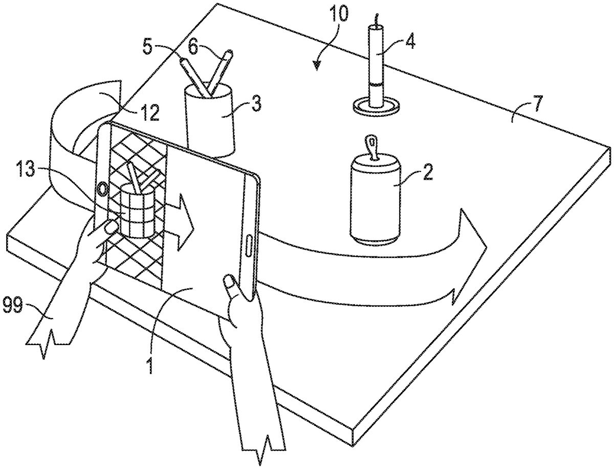
DETAILED DESCRIPTION FIG. 1shows steps of creating a physical model according to one embodiment. The virtual part of the game is played on a mobile device1, such as a tablet computer, a portable computer, or the like. The mobile device1has a capturing device, data storage, a processor, and a display. It will be appreciated, however, that the various embodiments of the process described herein may also be implemented on other types of processing devices. The processing device may comprise a capturing device, data storage, a processor, and a display integrated into a single physical entity; alternatively, one or more of the above components may be provided as one or more separate physical entities that may be communicatively connectable with each other otherwise to allow data transfer between them. Game software installed on the mobile device1adapts the mobile device1for performing the method according to one embodiment of the disclosure within the framework of an interactive game. The mobile device1presents a building tutorial to the user99. Following the instructions of the tutorial, the user99finds a number of physical objects2,3,4,5,6and arranges these physical objects2,3,4,5,6on a physical play zone7, such as a table top or a floor space, to form a physical model10of a game environment. Advantageously, the building tutorial includes hints11on how certain pre-determined physical properties of physical objects in the physical model of the game environment will be translated by the game system into characteristics of the virtual game environment to be created. This allows the user99to select the physical objects2,3,4,5,6according to these pre-determined physical properties to willfully/intentionally build the physical model in order to create certain predetermined characteristics/a certain game behaviour of the virtual game environment according to a pre-determined set of rules. By way of example,FIG. 1shows a hint in the form of a translation table indicating how different values ...
DETAILED DESCRIPTION
FIG. 1shows steps of creating a physical model according to one embodiment. The virtual part of the game is played on a mobile device1, such as a tablet computer, a portable computer, or the like. The mobile device1has a capturing device, data storage, a processor, and a display. It will be appreciated, however, that the various embodiments of the process described herein may also be implemented on other types of processing devices. The processing device may comprise a capturing device, data storage, a processor, and a display integrated into a single physical entity; alternatively, one or more of the above components may be provided as one or more separate physical entities that may be communicatively connectable with each other otherwise to allow data transfer between them. Game software installed on the mobile device1adapts the mobile device1for performing the method according to one embodiment of the disclosure within the framework of an interactive game. The mobile device1presents a building tutorial to the user99. Following the instructions of the tutorial, the user99finds a number of physical objects2,3,4,5,6and arranges these physical objects2,3,4,5,6on a physical play zone7, such as a table top or a floor space, to form a physical model10of a game environment. Advantageously, the building tutorial includes hints11on how certain pre-determined physical properties of physical objects in the physical model of the game environment will be translated by the game system into characteristics of the virtual game environment to be created. This allows the user99to select the physical objects2,3,4,5,6according to these pre-determined physical properties to willfully/intentionally build the physical model in order to create certain predetermined characteristics/a certain game behaviour of the virtual game environment according to a pre-determined set of rules. By way of example,FIG. 1shows a hint in the form of a translation table indicating how different values of a pre-determined physical property, here colour, are handled by the system. In particular, the user99is presented with the hint that green colours on physical objects will be used to define jungle elements, red colours will be used to define lava elements, and white colours will be used to define ice elements in the virtual game environment.
FIG. 2illustrates steps of creating a virtual model from the physical model10created by arranging physical objects2,3,4,5,6on a physical play zone7. The mobile device1is moved along a scanning trajectory12while capturing image/scan data13of the physical model10. The image data is processed by the processor of the mobile device1thereby generating a digital three-dimensional representation indicative of the physical model10as well as information on pre-determined physical properties, such as colour, shape and/or linear dimensions. The digital three-dimensional representation may be represented and stored in a suitable form in the mobile device, e.g. in a mesh form. The mesh data is then converted into a virtual toy construction model using a suitable algorithm, such as a mesh-to-LXFML code conversion algorithm as further detailed below. The algorithm analyses the mesh and calculates an approximated representation of the mesh as a virtual toy construction model made of virtual toy construction elements that are direct representations of corresponding physical toy construction elements.
Referring toFIGS. 3-7, steps of creating a virtual game environment from a physical model according to a further embodiment are illustrated by means of screen shots from a mobile device used for performing the steps.FIG. 3shows an image of a set-up of different everyday items found in a home and in a children's room as seen by a camera of the mobile device. These items are the physical objects used for building the physical model of the virtual game environment to be created by arranging the items on a table. The physical objects have different shapes, sizes and colours. The items include blue and yellow sneakers, a green lid for a plastic box, a green can, a folded green cloth, a yellow box, a red pitcher, a grey toy animal with a white tail, mane and forelock as well as a red cup placed as a fez hat, and further items. InFIG. 4the physical model is targeted using an augmented reality grid overlaid to the view captured by the camera of the mobile device. The camera is a depth sensitive camera and allows for a scaled augmented reality grid to be shown. The augmented reality grid indicates the targeted area captured, which in the present case is a square of 1 m by 1 m.FIG. 5shows a screen shot of the scanning process, where the mobile device with the camera pointed at the physical model is moved around, preferably capturing image data from all sides as indicated by the arrows and the angular scale. However, a partial scan may be sufficient depending on the nature of the three-dimensional image data required for a given virtual game environment to be created.FIG. 6shows a screen shot after a brickification engine has converted the three-dimensional scan data into a virtual toy construction model made to scale from virtual toy construction elements. The virtual toy construction model also retains information about different colours in the physical model. InFIG. 7the virtual toy construction model has been enhanced by defining game controlling elements into the scene, thereby creating a virtual game environment where essentially everything appears to be made of virtual toy construction elements.FIG. 7shows a screen shot of a playable figure exploring the virtual game environment. The playable figure is indicated in the foreground as a colourless/white, three-dimensional virtual mini-figure. Buttons on the right hand edge of the screen are user interface elements for the game play.
Now referring toFIGS. 8-17, steps of installing and playing a cyclic interactive game according to a yet further embodiment are illustrated schematically. InFIG. 8, the software required for configuring and operating a mobile device for its use in an interactive game system according to the present disclosure is downloaded and installed. Upon start-up of the game software a welcome page may be presented to the user as seen inFIG. 9, from which the user enters a building mode. The user may now be presented with a building tutorial and proceed to building a physical model and creating a virtual game environment as indicated inFIGS. 10 and 11, and as already described above with reference toFIGS. 1 and 2. The physical objects used for constructing the physical model are grey pencils, a brown book, a white candle standing upright in a brown foot, a white cup (in the right hand of the user inFIG. 10) and a red soda can (in the left hand of the user onFIG. 10). Once the virtual game environment is created, the user may proceed to game play by exploring the virtual game environment created as seen inFIG. 12. Before embarking on a virtual mission in the virtual game environment, the user may make a number of choices as, such as selecting a playable character and/or tools from a number of unlocked choices (top row inFIG. 13). A number of locked choices may also be shown (bottom row inFIG. 13).FIGS. 14 and 15show different screenshots of a playable character on different missions (grey figure with blue helmet). The playable character is equipped with a tool for harvesting resources (carrots). InFIG. 14, the playable character is merely on a collecting mission. Seen in the background of the screenshot ofFIG. 14is a lava-mountain created from the red soda can in the physical model. The same virtual game environment created from the same physical model is also shown inFIG. 15, but from a different angle and at a different point in the course of the game. The lava-mountain created from the red soda can is shown in the landscape on the right hand side. The white cup of the physical model has been turned into an iceberg surrounded in its vicinity by ice and snow. The game environment has now spawned monsters/adversaries that compete with the playable figure for the resources to be collected (e.g. carrots and minerals), and which may have to be defeated as a part of a mission. InFIG. 16, the user has successfully completed a mission and is rewarded, e.g. by an amount of in-game currency. The in-game currency can then be used to unlock new game features, such as tools/powers/new playable characters/game levels/modes or the like. After reward and unlocking of game features, the user may receive a new mission involving a rearrangement of the physical model, thereby initiating a new cycle of the interactive game. The cycle of a cyclic interactive game is shown schematically inFIG. 17. The game system provides a task (top) and the user creates a virtual game environment/scene from physical objects (bottom right); the user plays one or more game segments in the virtual game environment/scene (bottom left); and in response to the outcome of the game play, a new cycle is initiated by the game system (back to the top).
FIG. 18shows an example of a physical playable character model with different physical tool models. The physical playable character model is for use in an interactive game system. The playable character model may be fitted with a choice of the physical tool models. By way of example, a selection of physical tool models is shown in the bottom half ofFIG. 18. Each physical tool model represents specific tools, powers and/or skills.FIG. 19shows an interactive game system including the physical playable character model ofFIG. 18. The physical playable character model may be used for playing, e.g. role playing, in the physical model created by means of the physical objects as shown in the background. By entering information about the physical playable character model and the tools with which it is equipped in the game, a corresponding virtual playable character model is created for game play in the virtual game environment as indicated on the display of the handheld mobile device in the foreground ofFIG. 19(bottom right). Note also, that on the schematic view a physical play zone has been defined by a piece of green card board on the table top. The green card board has been decorated with colour pencils to mark areas on the physical play zone that in the virtual game environment are converted into rivers with waterfalls over the edge of the virtual scene as shown schematically on the handheld mobile device in the foreground.
An important step in creating the virtual game environment is the conversion of the digital three-dimensional representation obtained from, or at least created on the basis of data received from, the capturing device into a virtual toy construction model constructed from virtual toy construction elements or into another voxel-based representation. In the following an example will be described of a conversion engine adapted for performing such a conversion, in particular a conversion engine for conversion from a mesh representation into an LXFML representation. It will be appreciated that other examples of a conversion engine may perform a conversion into another type of representation.
With the evolution of computers and computer vision it is becoming easier for computers to analyze and represent 3D objects in a virtual world. Different technologies exist nowadays that facilitate the interpretation of the environment, creating 3D meshes out of normal pictures obtained from normal cameras or out of depth camera information.
This means that computers, smartphones, tablets and other devices will increasingly be able to represent real objects inside an animated world as 3D meshes. In order to provide an immersive game experience or other types of virtual game experiences, it would be of great value if whatever a computer could “see” and represent as a mesh could then be transformed into a model built out of toy construction elements such as those available under the name LEGO or at least as a voxel-based representation.
Virtual toy construction models may be represented in a digital representation identifying which virtual toy construction elements are comprised in the model, their respective positions and orientations and, optionally, how they are interconnected with each other. For example, the so-called LXFML format is a digital representation suitable for describing models constructed from virtual counterparts of construction elements available under the name. It is thus desirable to provide an efficient process for converting a digital mesh representation into a LEGO model in LXFML format or into a virtual construction model represented in another suitable digital representation.
Usually, 3D models are represented as meshes. These meshes are typically collections of colored triangles defined by the corners of the triangles (also referred to as vertices) and an order of how these corners should be grouped to form these triangles (triangle indexes). There is other information that a mesh could store but the only other thing relevant for this algorithm is the mesh color.
As described earlier, the algorithm receives, as an input, mesh information representing one or more objects. The mesh information comprises:Mesh vertices/vertex positions: the coordinates of the points that form the triangles, meaning points in space, e.g. represented as vectors (x,y,z), where x,y,z can be any real number.Triangle indexes: the indexes of the vertices in consecutive order so that they form triangles, i.e. the order in which to choose the vertices from the positions in order to draw the triangles in the mesh. For example,FIG. 20illustrates an example of an indexing scheme for a simple surface defined by 4 points labelled 0, 1, 2 and 3, respectively, defining a rectangle. In this example, an array of indexes like {0, 1, 2, 3, 0} may be defined to represent how triangles may be defined to represent the surface. This means that a process starts from point 0, proceed to point 1, then to point 2. That is the first triangle. The process may then proceed from the current point (point 2) to define the next triangle, so the process only needs the remaining 2 points, which are 3 and 0. This is done in order to use less data to represent the triangles.Mesh color information: the colors that the triangles have.
Embodiments of the process create a representation of a virtual construction model, e.g. an LXFML string format version 5 or above. The LXFML representation needs to include the minimum information that would be needed by other software tools in order to load the information inside. The following example will be used to explain an example of the information included n an LXFML file:
1234567891011121314
The first line merely states the format of the file.
The second line contains information about the LXFML version and the model name. The LXFML version should preferably be 5 or higher. The model name serves as information only. It does not affect the loading/saving process in any way.
A section is where optional information is stored. Different applications can store different information in this section if they need to. The information stored here does not affect the loading process.
Line 4 provides optional information about what application exported the LXFML file. This may be useful for debugging purposes.
The subsequent lines include the information about the actual toy construction elements (also referred to as bricks). The refID should be different for every brick of the model (a number that is incremented every time a brick is exported will do just fine). The design ID gives information about the geometry of the brick and the materials give information about the color. The transformation is the position and rotation of the brick represented by a 4 by 4 matrix but missing the 3rdcolumn.
This information is considered sufficient. One could test the validity of an LXFML file by loading it with the free tool LEGO Digital Designer that can be found at http://ldd.lego.com.
FIG. 21shows a flow diagram illustrating the steps of an example of a process for converting a mesh into a representation of a virtual toy construction model. These steps are made independent because sometimes not all of them are used, depending on the situation.
In initial step S1, the process receives a mesh representation of one or more objects. For the purpose of the present description, it will be assumed that the process receives a mesh including the following information:Vm=mesh vertices.Tm=mesh triangles.Cm=mesh color; (Per vertex color)
It will be appreciated that, instead of a mesh color, the mesh may represent another suitable attribute, such as a material or the like. Nevertheless, for simplicity of the following description, reference will be made to colors.
In an initial conversion step S2, the process converts the mesh into voxel space. The task addressed by this sub-process may be regarded as the assignment of colors (in this example colors from a limited palette2101of available colors, i.e. colors from a finite, discrete set of colors) to the voxels of a voxel space based on a colored mesh. The mesh should fit the voxel space and the shell that is represented by the mesh should intersect different voxels. The intersecting voxels should be assigned the closest color from the palette that corresponds to the local mesh color. As this technology is used in computer-implemented applications such as gaming, performance is very important.
The initial sub-process receives as an input a mesh that has color information per vertex associated with it. It will be appreciated that color may be represented in different ways, e.g. as material definitions attached to the mesh. Colors or materials may be defined in a suitable software engine for 3D modelling, e.g. the system available under the name “Unity”.
The mesh-to-voxel conversion process outputs a suitable representation of a voxel space, e.g. as a 3-dimensional array of integer numbers, where each element of the array represents a voxel and where the numbers represent the color ID, material ID or other suitable attribute to be assigned to the respective voxels. All the numbers should be 0 (or another suitable default value) if the voxel should not be considered an intersection; otherwise, the number should represent a valid color (or other attribute) ID from the predetermined color/material palette, if a triangle intersects the voxel space at the corresponding voxel. The valid color should preferably be the closest color from the predetermined palette to the one the triangle intersecting the voxel has.
FIG. 22Ashows an example of a mesh representation of an object whileFIG. 22Bshows an example of a voxel representation of the same object where the voxel representation has been obtained by an example of the process described in the following with reference toFIG. 23.
So the task to be performed by the initial sub-process may be regarded as: given a mesh model, determine a voxel representation that encapsulates the mesh model and has as voxel color the closest one of a predetermined set of discrete colors to the mesh intersecting the voxel(s).
Initially converting the mesh into a voxel representation is useful as it subsequently facilitates the calculation of where different toy construction elements should be positioned, Voxels may be considered boxes of size X by Y by Z (although other types of voxels may be used). Voxels may be interpreted as 3D pixels. The conversion into voxels may be useful in many situations, e.g. when the model is to be represented as virtual toy construction elements in the form of box-shaped bricks of size X′ by Y′ by Z′. This means that any of the bricks that we might have in the model will take up space equal to a multiple of X, Y, Z by the world axis x, y and z.
In order to create the voxel space needed for the model that is to be converted, the process starts at step S2301by creating an axis-aligned bounding box around the model. The bounds can be computed from the mesh information. This can be done in many ways; for example the Unity system provides a way to calculate bounds for meshes. Alternatively, a bound can be created out of two points: one containing the minimum coordinates by x, y and z of all the vertices in all the meshes and the other containing the maximum values by x, y and z, like in the following example:Pminx=Minx(Vm1x,Vm2x. . . ) Pmaxx=Maxx(Vm1x,Vm2x. . . )Pminy=Miny(Vm1y,Vm2y. . . ) Pmaxy=Maxy(Vm1y,Vm2y. . . )Pminz=Minz(Vm1z,Vm2z. . . ) Pmaxz=Maxz(Vm1z,Vm2z. . . )Pmin=(Pminx,Pminy,Pminz) Pmax=(Pmaxx, Pmaxy, Pmaxz)
Pmin and Pmax are the minimum and maximum points with coordinates x, y and z. Max and Min are the functions that get the minimum and maximum values from an array of vectors Vm by a specific axis (x, y or z).
Having the opposite corners of a box should be sufficient to define it. The box will have the size B=(bx, by, bz) by axis x, y and z. This means that B=Pmax−Pmin;
In a subsequent step S2302, the process divides the voxel space into voxels of a suitable size, e.g. a size (dimx, dimy, dimz) matching the smallest virtual toy construction element of a system of virtual toy construction elements. Preferably the remaining virtual toy construction elements have dimensions corresponding to integer multiples of the dimensions of the smallest virtual toy construction element. In one example, a voxel has dimensions (dimx, dimy, dimz)=(0.8, 0.32, 0.8) by (x,y,z) which is the size of a 1×1 Plate LEGO plate (LEGO Design ID: 3024). By creating the Voxel Space corresponding to the bounding box we will create a Matrix of size V(vx,vy,vz), where vx=bx/dimx+1, vy=by/dimy+1 and vz=bz/dimz+1. The +1 appears because the division will almost never be exact and any remainder would result in the need of having another voxel that will need filling.
The matrix will contain suitable color IDs or other attribute IDs. This means that a voxel will start with a default value of 0 meaning that in that space there is no color. As soon as that voxel needs to be colored, that specific color ID is stored into the array. In order to process the mesh, the process processes one triangle at a time and determines the voxel colors accordingly, e.g. by performing the following steps:Step S2303: Get next triangleStep S2304: Get the intersection of the triangle with the voxel spaceStep S2305: Compute a raw voxel color of the intersecting voxel(s).S2306: Get the color ID of the closest color from the raw voxel color and so the subsequent bricks can be created with a valid color. StepS2307: Mark the voxel(s) with the determined color ID.
These steps are repeated until all triangles are processed.
The computation of the raw voxel color to be assigned to the intersecting voxels (Step S2305) may be performed in different ways. Given the input, the color of a voxel can be calculated based on the intersection with the voxel and the point/area of the triangle that intersects with the voxel or, in case of triangles that are small and the color variation is not that big, it could be assumed that the triangle has the same color and that is the average of the 3 colors in the corners. Moreover, it is computationally very cheap to calculate the average triangle color and approximate just that one color to one of the set of target colors. Accordingly:In one embodiment, the process may simply average out the color of the triangle using the 3 vertex colors and then use the average color for all intersections.In an alternative embodiment, the process computes where on the triangle is the intersection with the voxel space.FIG. 24illustrates an example of a triangle and a determined intersection point X of the triangle with the voxel space. Then the process computes the color as follows (seeFIG. 24): Having the 3 colors Ca, Cb and Cc associated to the vertices/vectors A, B and C, the intersecting color is C=⅙ *ΣBA[(Xab*Cb+(AB−Xab)*Ca)/AB+(Xcb*Cb+(CB−Xcb)*Cc)/CB], where Xab is the distance from the intersection of the triangle with the voxel space along the AB axis, AB is the distance from a to B and the sum represents the same process applied for A, B and C to obtain a color blend.
While the first alternative is faster, the second alternative provides higher quality results.
The determination of the intersection of the triangle with the voxel space (step S2304) may be efficiently performed by the process illustrated in FIGS.25and26and as described as follows. In particular,FIG. 25illustrates a flow diagram of an example of the process andFIG. 26illustrates an example of a triangle2601. Since it is fairly easy to convert a point in space to a coordinate in voxel space, the process to fill the voxels may be based on points on the triangle as illustrated inFIG. 26. The steps of the sub-process, which is performed for each triangle of the mesh, may be summarized as follows:
Step S2501: select one corner (corner A in the example ofFIG. 26) and the edge opposite the selected corner (edge BC in the example ofFIG. 26).
Step S2502: Define a sequence of points BC1-BC5that divide the opposite edge (BC) into divisions equal to the smallest dimension of a voxel, e.g. dimy=0.32 in the above example. The points may be defined as end points of a sequence of vectors along edge BC, where each vector has a length equal to the smallest voxel dimension. Since, in 3D, it is highly unlikely to have integer divisions, the last vector will likely end between B and C rather than coincide with C.
The process then processes all points BC1-BC5defined in the previous step by performing the following steps:
Step S2503: Get next point
Step S2504: The process defines a line connecting the corner (A) picked at step S2501with the current point on the opposite edge.
Step S2505: The process divides the connecting line into divisions with the size equal to the smallest dimension of a voxel, again dimy=0.32 in the above example. Hence, every point generated by the split of step S2502, connected with the opposite corner of the triangle (A in the example ofFIG. 26) forms a line which is to be split in the same way, but starting from the point on the edge (BC) so that the last point that might not fall into the point set because of the non-integer division be A. At last, AC should be split into points.
Step S2506: For every point on the line that was divided at Step S2505and for point A, the process marks the voxel of the voxel space that contains this point with the raw color computed as described above with reference to step S2305ofFIG. 23. This mapping may be done very efficiently by aligning the model to the voxel space and by dividing the vertex coordinates to the voxel size. The process may allow overriding of voxels. Alternatively, the process may compute weights to determine which triangle intersects a voxel most. However, such a computation is computationally more expensive.
This simple pseudocode shows how the voxel representation of the mesh can be created using just the mesh information. The amount of operations done is not minimal as the points towards the selected corner (selected at Step S2501) tend to be very close to each other and not all of them would be needed. Also the fact that the triangle could be turned at a specific angle would mean that the division done at Step S2506may take more steps than necessary. However, even though there is a lot of redundancy, the operation is remarkably fast on any device and the complexity of calculations needed to determine the minimum set of points would likely result in having a slower algorithm.
Again referring toFIG. 23, the determination of the closest color from a palette of discrete colors (step S2306) may also be performed in different ways:In one embodiment, which results in a high quality color mapping, the process initially transforms RGB colors into LAB space. With the LAB representation of colors, the process applies the DeltaE color distance algorithm to compute the distance from the actual color (as determined from the mesh) and the other available colors from the palette. A more detailed description of this method is available at http://en.wikipedia.org/wiki/Color_difference.In another embodiment, which is faster than the first embodiment, the process calculates the difference between the valid colors of the palette and the given color (as determined from the mesh). The process then selects the color of the palette that corresponds to the shortest distance.
One way to find the shortest distance is to compare all distances in 3D. This means that any color that is to be approximated has to be compared with all possible colors from the palette. A more efficient process for determining the closest distance between a color and the colors of a palette of discrete colors will be described with reference toFIG. 27:
All colors in RGB space may be represented in 3D as an 8thof a sphere/ball sectioned by the X, Y and Z planes with a radius of 255. If a color C with components rC, gC, bC containing the red, green and blue components is given as input for the conversion step, color C will be situated at distance D from the origin.
The minimum distance may then be found by an iterative process starting from an initial value of the minimum distance. The maximum distance from the origin to the closest target color from the palette that should be found must be no larger than the distance from the origin to the original color plus the current minimum distance. The initial minimum is thus selected large enough to cover all possible target colors to ensure that at least one match is found.
An example of how the process works is as follows: a current minimum distance is found, meaning that there is a target color that is close to the input color. Now, no target color can be found in such way that it is closer to the original color, yet further away from origin than the distance between the original color and the origin plus the current minimum distance. This follows from the fact that the minimum distance determines the radius of the sphere that has the original color in its center and contains all possible, better solutions. Any better solution should thus be found within said sphere; otherwise it would be further away from the original color. Consequently, for a given current minimum distance, only colors need to be analyzed that are at a distance from the origin smaller than the original color distance+the current minimum.
The above conversion process results in a voxel model of the hull/contour of the object or objects. It has been found that the process provides a quality output at an astounding speed because:If all the units are at maximum distance equal to the minimum size of a voxel, one can't get 2 points that are further away than a voxel so there will never be holes.If the triangles are small and many, and if the model is big, all the small voxel overrides that might give a voxel that does not have the best color for a few voxel will be tolerable.The color approximation is good enough while at the same time saves a lot of computation power.
This solution may be compared in performance to the standard solutions (raycasting and volume intersection) which instead of just using a given set of points in space try to determine if triangles intersect different volumes of space and, in some cases, some methods even try to calculate the points where the triangle edges intersect the voxels. The volume intersection method is expected to be the slowest, but the intersection points are expected to provide accurate areas of intersection which could potentially facilitate a slightly more accurate coloring of the voxels.
Instead of computing different intersections, another method that is commonly used to determine intersections is called raycasting. Rays can be casted in a grid to determine what mesh is hit by specific rays. The raycasting method is not only slower but also loses a bit of quality as only the triangles hit by the rays contribute to the coloring. The raycasting method could give information about depth and could help more if operations need to be done taking in the consideration the interior of the model.
Again referring toFIG. 21, the mesh-to-voxel conversion of step S2typically results in a hollow hull, as only voxels intersecting the surface mesh have been marked with colors. In some situations it may be desirable to also map colors onto internal voxels while, in other situations, it may be desirable not to fill out the voxel model. For example, sometimes the model should be empty, e.g. when the model represents a hollow object, e.g. a ball. Moreover, it takes more time to calculate what is the inside volume of the model and it also affects the amount of bricks in the model. This makes all the subsequent steps slower because more information is handled. On the other hand, sometimes, especially if creating landscapes, it is desirable that a model is full rather than just an empty shell.
Accordingly, in the subsequent, optional step S3, the process may fill the internal, non-surface voxels with color information. The main challenge faced when trying to fill the model is that it is generally hard to detect if the voxel that should be filled is inside the model or outside. Ray casting in the voxel world may not always provide a desirable result, because if a voxel ray intersects 2 voxels, this does not mean that all voxels between the two intersection points are inside the model. If the 2 voxels contained, for example very thin triangles, the same voxel could represent both an exit and an entrance.
Raycasting on the mesh can be computationally rather expensive and sometime inaccurate, or it could be accurate but even more expensive, and therefore a voxel based solution may be used for better performance.
It is considerably easier to calculate the outside surface of the model because the process may start with the boundaries of the voxel world. If those points are all taken then everything else is inside. For every voxel that is not occupied because of triangle intersections one can start marking every point that is connected to that point as being a point in the exterior. This procedure can continue recursively and it can fill the entire exterior of the model.
Now that the edge is marked and the exterior is marked, everything in the voxel space that is unmarked (still holds a value of 0) is inside the model.
Now, a voxel raycasting can be done to shoot rays by any axis and fill in any unoccupied voxel. Currently, the color of voxel that intersects the entering ray is used to color the interior. As the mesh holds no information about how should the interior be colored, this coloring could be changed to be application specific.
In subsequent, optional step S4, the created voxel representation may be post-processed, e.g. trimmed. For example, such a post-processing may be desirable in order to make the voxel representation more suitable for conversion into a virtual toy construction model. For example, toy construction elements of the type known as LEGO often have coupling knobs. When the volume defined by the mesh is not too big, an extra knob could make a huge difference for the overall appearance of the model; therefore, for bodies with volumes less than a certain volume, an extra trimming process may be used. For example, the minimum volume may be selected as 1000 voxels or another suitable limit.
The trimming process removes the voxel on top of another voxel; if there is only one voxel that exists freely it is removed also. This is done because the LEGO brick also has knobs that connect to other bricks. Since the knob of the last brick on top is sticking out it could mark another voxel but we might not want to put a brick there because it will make the already existing small model even more cluttered. For this reason the extra trimming process may optionally be used for small models. Of course, it could also be used on bigger models but it will introduce extra operations that might not provide observable results.
The trimming process may e.g. be performed as follows: For every occupied voxel, the process checks if there is an occupied voxel on top; if not, it marks the occupied voxel for deletion. Either lonely voxels or the top most voxels will be removed this way. The voxels on top are collected and removed all at the same time because if they would remove themselves first the voxel underneath might appear as the top-most voxel.
After the voxel space is filled (and, optionally, trimmed), either just the contour or the interior also, some embodiments of the process may create a virtual environment directly based on the voxel representation while other embodiments may create a toy construction model as described herein.
Accordingly, in the subsequent step S5, the process parses the voxel space and creates a data structure, e.g. a list, of bricks (or of other types toy construction elements). It will be appreciated that, if a raw voxel representation of a virtual environment is desired, alternative embodiments of the process may skip this step.
In order to obtain the bricks that can be placed, a brick evolution model is used, i.e. a process that starts with a smallest possible brick (the 3024, 1×1 plate in the above example) and seeks to fit larger bricks starting from the same position. Hence the initial smallest possible brick is caused to evolve into other types of bricks. This can be done recursively based on a hierarchy of brick types (or other types of toy construction elements). Different bricks are chosen to evolve into specific other bricks. To this end the process may represent the possible evolution paths by a tree structure. When placing a brick the process will try to evolve the brick until it cannot evolve anymore because there is no other brick it can evolve into or because there are no voxels with the same color it can evolve over.
An example of this would be: a 1×1 Plate is placed in the origin. It will try to evolve into a 1×1 Brick by looking to see if there are 2 voxels above it that have the same color. Assuming there is only one and therefore it cannot evolve in that direction, the process will then try to evolve the brick into a 1×2 Plate in any of the 2 positions (normal, 90 degree rotated around the UP axis). If the brick is found to be able to evolve into a 1×2 plate then the process will continue until it will run out of space or evolution possibilities. In one embodiment, the supported shapes are 1×1 Plate, 1×2 Plate, 1×3 Plate, 1×1 Brick, 1×2 Brick, 1×3 Brick, 2×2 Plate, 2×2 Brick, but more or other shapes can be introduced in alternative embodiments.
After the brick evolution of a brick has finished, the process clears the voxel space at the location occupied by the evolved brick. This is done in order to avoid placing other bricks at that location. The process then adds the evolved brick to a brick list.
The list of bricks thus obtained contains information about how to represent the bricks in a digital world with digital colors.
Optionally, in subsequent step S6, the process modifies the created toy construction model, e.g. by changing attributes, adding game-control elements and/or the like as described herein. This conversion may be at least in part be performed based on detected physical properties of the real world scene, e.g. as described above.
In subsequent step S7, the process creates a suitable output data structure representing the toy construction model. For example, in one embodiment, the bricks may be converted into bricks that are suitable to be expressed as an LXFML file. This means that a transformation matrix may need to be calculated and, optionally, the colors may need to be converted to a valid color selected from a predetermined color palette (if not already done in the previous steps).
The transform matrix may be built to contain the rotation as a quaternion, the position and the scale (see e.g. http://www.euclideanspace.com/maths/geometry/affine/matrix4×4/ for more detailed information on matrices and http://www.euclideanspace.com/maths/geometry/rotations/conversions/quaternionToMatrix/ more info on quaternion transformation). All the bricks may finally be written in a suitable data format, e.g. in the way described above for the case of an LXMF format.
With reference toFIGS. 28, 29A-B and30, another embodiment of a process for creating a virtual game environment from a physical model will now be described. In particular,FIG. 28shows a flow diagram of another embodiment of a process for creating a virtual game environment from a physical model andFIGS. 29A-Band30illustrate examples of steps of creating a virtual game environment from a physical model according to a further embodiment.
In initial step S2801, the process obtains scan data, i.e. a digital three-dimensional representation of the physical model, e.g. as obtained by scanning the physical model by means of a camera or other capturing device as described herein. The digital three-dimensional representation may be in the form of a surface mesh as described herein.FIG. 29Aillustrates an example of a scanning step for creating a virtual model from a physical model of a scene. The physical model of the scene comprises physical objects2902and2903arranged on a table or similar play zone. A mobile device2901is moved along a scanning trajectory while capturing image/scan data of the physical model. In this example, the physical objects include a number of everyday objects2902and a physical toy construction model2903of a car.
In step S2802, the process recognizes one or more physical objects as known physical objects. To this end, the process has access to a library2801of known physical objects, e.g. a database including digital three-dimensional representations of each known object and, optionally, additional information such as attributes to be assigned to the virtual versions of these objects, such as functional attributes, behavioral attributes, capabilities, etc. In the example ofFIGS. 29A-B, the process recognizes the physical toy construction model2903as a known toy construction model.
In step S2803, the process removes the triangles (or other geometry elements) from the mesh that correspond to the recognized object, thus creating a hole in the surface mesh.
In step S2804, the process fills the created hole by creating triangles filling the hole. The shape and colors represented by the created triangles may be determined by interpolating the surface surrounding the hole. Alternatively, the created surface may represent colors simulating a shadow or after-glow of the removed object.
In subsequent step S2805, the process creates a virtual environment based on the thus modified mesh, e.g. by performing the process ofFIG. 21.
In subsequent step S2806, the process creates a virtual object based on the information retrieved from the library of know objects. For example, the virtual object may be created as a digital three-dimensional representation of a toy construction model. The virtual object may then be inserted into the created virtual environment at the location where the mesh has been modified, i.e. at the location where the object had been recognized. The virtual object is thus not merely a part of the created landscape or environment but a virtual object (e.g. a virtual item or character) that may move about the virtual environment and/or otherwise interact with the created environment.FIG. 29Billustrates an example of the created virtual environment where the physical objects2902of the real-world scene are represented by a virtual toy construction model2912as described herein. Additionally, a virtual object2913representing the recognized car is placed in the virtual environment as a user-controllable virtual object that may move about the virtual environment in response to user inputs. The virtual environment ofFIG. 29is stored on the mobile device or on a remote system, e.g. in the cloud so as to allow the user to engage in digital game play using the virtual environment even when the user is no longer in the vicinity of the physical model or when the physical model no longer exists. It will be appreciated that the process may also be performed in an augmented reality context, where the virtual environment is displayed in real time while the user captures images of the physical model, e.g. as illustrated inFIG. 30.
FIG. 31shows a flow diagram of another embodiment of a process for creating a virtual game environment from a physical model.
In initial step S3101, the process obtains scan data, i.e. a digital three-dimensional representation of the physical model, e.g. as obtained by scanning the physical model by means of a camera or other capturing device as described herein. The digital three-dimensional representation may be in the form of a surface mesh as described herein.
In step S3102, the process recognizes one or more physical objects as known physical objects. To this end, the process has access to a library3101of known physical objects, e.g. a database including information such as information about a predetermined theme or conversion rules that are associated with and should be triggered by the recognized object.
In subsequent step S3103, the process creates a virtual environment based on the thus modified mesh, e.g. by performing the process ofFIG. 21.
In subsequent step S3104, the process modifies the created virtual environment by applying one or more conversion rules determined from the library and associated with the recognized object.
It will be appreciated that, in some embodiments, the process may, responsive to recognizing a physical object, both modify the virtual environment as described in connection withFIG. 31and replace the recognized object by a corresponding virtual object as described in connection withFIG. 28.
Embodiments of the method described herein can be implemented by means of hardware comprising several distinct elements, and/or at least in part by means of a suitably programmed microprocessor.
In the claims enumerating several means, several of these means can be embodied by one and the same element, component or item of hardware. The mere fact that certain measures are recited in mutually different dependent claims or described in different embodiments does not indicate that a combination of these measures cannot be used to advantage.
It should be emphasized that the term “comprises/comprising” when used in this specification is taken to specify the presence of stated features, elements, steps or components but does not preclude the presence or addition of one or more other features, elements, steps, components or groups thereof.
Claims
- A method of creating a virtual game environment/scene from a physical model, the method comprising the steps of: receiving a mesh digital three-dimensional representation of the physical model;converting the mesh digital three-dimensional representation into a voxel representation of the physical model including a plurality of voxels at voxel locations, a portion of the plurality of voxels intersecting the mesh digital three-dimensional representation;assigning a voxel attribute identification to the portion of the plurality of voxels intersecting the mesh digital three-dimensional based on an attribute of the mesh digital three-dimensional representation;converting the voxel representation into a virtual toy construction model including virtual toy construction elements;and defining game controlling elements in the virtual toy construction model based on physical attributes of the physical model.
- The method according to claim 1, wherein the game controlling elements include animated properties based on the virtual toy construction model and the physical attributes of the physical model.
- The method according to claim 1, further comprising the step of discriminating exterior voxels from interior voxels of the plurality of voxels by equating the portion of the plurality of voxels intersecting the mesh digital three-dimensional representation and adjacent voxels to exterior voxels.
- The method according to claim 3, further comprising the step of filling interior voxels of the plurality of voxels with color information.
- The method according to claim 1, further comprising the step of trimming the voxel representation of the physical model by: discriminating the plurality of voxels to determine occupied voxels and unoccupied voxels;checking each occupied voxel to determine if there is an adjacent unoccupied voxel;and removing the adjacent unoccupied voxel.
- The method according to claim 1, wherein converting the voxel representation of the physical model into a virtual toy construction model includes: parsing the voxel representation of the physical model to create a list of virtual toy construction elements that are configured to match a color and size of a respective voxel;and dimensioning the virtual toy construction elements to a location of the respective voxel by recursively applying larger virtual toy construction elements on the list to the location of the respective voxel while maintaining a color match, beginning with the smallest virtual toy construction element, yielding a correct virtual toy construction element.
- The method according to claim 6, further comprising the step of clearing the location of the respective voxel once the correct virtual toy construction element has been determined.
- The method according to claim 6, further comprising the step of dimensioning the virtual toy construction elements for all voxel locations of the voxel representation, wherein the total virtual toy construction elements dimensioned to all voxel locations of the voxel representation tallies to an integer multiple of the dimensions of the smallest virtual toy construction element.
- The method according to claim 1, wherein the mesh digital three-dimensional representation of the physical model includes mesh vertices, mesh triangles, and the attribute, wherein the attribute is selected from the group consisting of a color, texture, transparency, material.
- The method according to claim 1, wherein assigning a voxel attribute identification to the plurality of voxels intersecting the mesh digital three-dimensional is also based on a palette of colors based on virtual toy construction elements.
- The method according to claim 1, further comprising the step of, prior to receiving the mesh digital three-dimensional representation of the physical model, scanning the physical model using a capturing device.
- The method according to claim 1, wherein converting the mesh digital three-dimensional representation into a voxel representation includes: creating an axis-aligned bounding box around the physical model to form a voxel space;dividing the voxel space into the plurality of voxels matching, the size of the plurality of voxels corresponding to the smallest virtual toy construction elements of a system of virtual toy construction elements.
- The method according to claim 1, wherein converting the mesh digital three-dimensional representation into a voxel representation includes processing the mesh digital three-dimensional representation by: analyzing a triangle of the mesh digital three-dimensional representation;and determining the intersection of the triangle with the voxel representation.
- The method according to claim 1, wherein assigning a voxel attribute identification includes: computing a raw voxel color of the portion of the plurality of voxels intersecting the mesh digital three-dimensional representation;determining the color ID of the closest color to the raw voxel color;and marking the voxel with the determined color ID.
- The method according to claim 1, wherein the attribute is selected from the group consisting of a color, texture, transparency, and material;and wherein the voxel attribute identification is a closest voxel attribute identification of a predetermined set.
- A method of creating a toy construction element game environment/scene from a physical model, the method comprising the steps of: receiving a digital three-dimensional representation of the physical model;converting the digital three-dimensional representation of the physical model into a voxel representation of the physical model including a plurality of voxels at voxel locations;parsing the voxel representation of the physical model to create a list of virtual toy construction elements that are configured to match the color and size of a respective voxel of the plurality of voxels;and dimensioning a virtual toy construction element to a location of the respective voxel by recursively applying larger virtual toy construction elements on the list to the location of the respective voxel while maintaining a color match, beginning with the smallest virtual toy construction element, yielding a correct virtual toy construction element, wherein the toy construction element game environment/scene includes one or more correct virtual toy construction elements.
- The method according to claim 16, further comprising the step of, prior to receiving a digital three-dimensional representation of the physical model, scanning the physical model using a capturing device.
- The method according to claim 16, further comprising the step of clearing the location of the respective voxel once the correct virtual toy construction element has been determined.
- The method according to claim 16, wherein dimensioning a virtual toy construction element to a location of the respective voxel includes evolving the virtual toy construction element by: determining if there are adjacent voxels of the plurality of voxels having the same color;and extending the virtual toy construction element to a larger size based on the determination of adjacent voxels.
- A non-transitory computer program product comprising program code configured to cause, when executed by a data processing system, the data processing system to: receive a digital three-dimensional representation of the physical model;convert the digital three-dimensional representation of the physical model into a voxel representation of the physical model including a plurality of voxels at voxel locations;parse the voxel representation of the physical model to create a list of virtual toy construction elements that are configured to match the color and size of a respective voxel of the plurality of voxels;and dimension the virtual toy construction elements to a location of the respective voxel by recursively applying larger virtual toy construction elements on the list to the location of the respective voxel while maintaining a color match, beginning with the smallest virtual toy construction element, yielding a correct virtual toy construction element, wherein the toy construction element game environment/scene includes one or more correct virtual toy construction elements.
Disclaimer: Data collected from the USPTO and may be malformed, incomplete, and/or otherwise inaccurate.