U.S. Pat. No. 11,491,394
MOBILE VIDEO GAME CONTROLLER
AssigneePerformance Designed Products LLC
Issue DateMay 3, 2021
Illustrative Figure
Abstract
A video game controller for use with a smartphone includes a top panel hinged relative to a bottom panel, with the bottom panel having control inputs for playing video games. The top panel folds onto a bottom panel in a closed configuration to easily fit in a pocket of the user's garment, such as pants pocket, shirt pocket, jacket pocket, etc.). The top panel pivots relative to the bottom panel to an open configuration to support the smartphone on the top panel during use irrespective of the size of the smartphone.
Description
DETAILED DESCRIPTION FIGS. 1A-11show a mobile video game controller100(hereafter “the controller”) for use with a smartphone200that can be removably coupled to the controller100. The controller100has a top panel10and a bottom panel20connected by a hinge40, allowing the top panel10to be swiveled relative to the bottom panel20. The controller100has the form of a case (e.g. a phone case) with smooth (e.g., planar) top and bottom outer surfaces and rounded corners. In the illustrated figures, the controller100has a generally rectangular shape when in the closed position with a compact form factor (e.g., relatively small thickness when in the closed position where the top panel10is adjacent the bottom panel20), advantageously providing improved portability and pocketability of the controller100(e.g., allowing the controller100to be stored in a garment pocket of the user, such as a pants pocket, shirt pocket or jacket pocket, while in the closed position). The controller100allows the smartphone to operate as a gaming console to play video games accessed via the smartphone200(e.g., cloud or online games). As such, the controller100is a phone console mobile controller. FIG. 1Ashows the controller100in a closed position with the top panel10adjacent (e.g., folded over) the bottom panel20.FIG. 1Bshows the controller in an open position with the top panel10extending at an angle (e.g., obtuse angle greater than 90 degrees, such as 120 degrees) relative to the bottom panel20, with the smartphone200attached to the top panel10and used in a gaming mode.FIG. 1Cshows the controller100oriented in a vertical direction (e.g., along the major axis of the controller100) with the smartphone200attached to the top panel10, which allows a user to use the smartphone200(e.g., in a non-gaming mode) in a phone mode while the controller100supports the smartphone200(e.g., in an upright position) on a support surface (e.g., a table).FIG. 1Dshows the controller100with the top panel10rotated more than 180 degrees (e.g., approximately 230-280 degrees) relative ...
DETAILED DESCRIPTION
FIGS. 1A-11show a mobile video game controller100(hereafter “the controller”) for use with a smartphone200that can be removably coupled to the controller100. The controller100has a top panel10and a bottom panel20connected by a hinge40, allowing the top panel10to be swiveled relative to the bottom panel20.
The controller100has the form of a case (e.g. a phone case) with smooth (e.g., planar) top and bottom outer surfaces and rounded corners. In the illustrated figures, the controller100has a generally rectangular shape when in the closed position with a compact form factor (e.g., relatively small thickness when in the closed position where the top panel10is adjacent the bottom panel20), advantageously providing improved portability and pocketability of the controller100(e.g., allowing the controller100to be stored in a garment pocket of the user, such as a pants pocket, shirt pocket or jacket pocket, while in the closed position). The controller100allows the smartphone to operate as a gaming console to play video games accessed via the smartphone200(e.g., cloud or online games). As such, the controller100is a phone console mobile controller.
FIG. 1Ashows the controller100in a closed position with the top panel10adjacent (e.g., folded over) the bottom panel20.FIG. 1Bshows the controller in an open position with the top panel10extending at an angle (e.g., obtuse angle greater than 90 degrees, such as 120 degrees) relative to the bottom panel20, with the smartphone200attached to the top panel10and used in a gaming mode.FIG. 1Cshows the controller100oriented in a vertical direction (e.g., along the major axis of the controller100) with the smartphone200attached to the top panel10, which allows a user to use the smartphone200(e.g., in a non-gaming mode) in a phone mode while the controller100supports the smartphone200(e.g., in an upright position) on a support surface (e.g., a table).FIG. 1Dshows the controller100with the top panel10rotated more than 180 degrees (e.g., approximately 230-280 degrees) relative to the bottom panel20, allowing the user to use the smartphone200in a media mode (e.g., to watch videos) while the controller100supports the smartphone200on a support surface (e.g., a table).
The controller100includes a cable50with a connector55that connects to the power jack of the smartphone200. The controller100(e.g., electronics in the controller100, control inputs22) communicate with the smartphone200via the connector55once it is coupled to the power jack of the smartphone200. The controller100(e.g., the electronics in the controller, the control inputs22) are powered by power communicated from the smartphone200to the controller100via the cable50and connector55. That is, in one implementation, the controller100does not have its own power source (e.g., there are no batteries in the controller100).
With reference toFIGS. 2-4, the controller100has one or more (e.g., multiple) control inputs22on the bottom panel20that the user can operate to play the video game on the smartphone200. The control inputs22can include one or more buttons BB, directional pads or D-pads DP, thumbsticks TS, etc. (e.g., digital buttons, digital bumpers B, analog triggers T, analog joysticks with digital center push button, home button, options button, menu button). In one implementation, the control inputs22can be arranged in a console layout similar to typical video game controllers, allowing the user to easily and intuitively operate the control inputs22while playing a video game on the smartphone200while it's connected to the controller100. The control inputs22can be symmetrically arranged about a centerline of the bottom panel20across a width of the bottom panel20between a front and a rear edge of the bottom panel20(seeFIG. 5). The control inputs22allow the user to engage in complex game play and execute complex moves in video games played on the smartphone200. The controller100can also have one or more lighting elements27, such as light emitting diodes (LEDs) (e.g., four LEDs), adjacent an edge of the bottom panel20, as best shown inFIG. 5.
The controller100has an audio jack24(e.g., 3.5 mm 4-pole audio jack) for connecting a headset cable HS of a headset (not shown), allowing the user to play video games more discretely (e.g., while on the subway, airplane, train, taxi, etc.). The audio jack24, when the headset is connected to it, also allows for the user to experience low-latency audio while playing a video game.
The controller100has a connector26for connecting a power cable60(seeFIG. 4). The cable60can be connected to power source (e.g. wall outlet, computer USB-A or USB-C connector, APPLE® LIGHTNING® connector). Electronics in the controller100pass power from the power source via the cable60to the smartphone200via the cable50and connector55to power the smartphone200(e.g., charge the battery of the smartphone200). That is, the controller100allows for pass through power from the power source to the smartphone200to power the smartphone200(e.g., while operating the controller100during gaming, for extended gaming use of the controller100). The connector26can in one implementation be a Universal Serial Bus type C (USB-C) connector. However, the connector26can be other suitable electrical connectors (e.g., APPLE® LIGHTNING® connector).
FIGS. 6A-6Bshow a front perspective and a rear perspective view top panel10, respectively. The top panel10has a slot12defined relative to a rear plate14of the top panel10. In one implementation, the slot12can be U shaped, with an open end at an edge of the top panel10and a closed end toward an opposite edge of the top panel10. The cable50and connector55are connected to the top panel50and can be attached (e.g. clipped) to the top panel10when not connected to the smartphone200to allow storage of the cable50and connector55so the cable does not dangle relative to the top panel10(e.g., the cable50clipped by a channel or slot11on the edge of the top panel10and the connector55extending into a slot in a side of the top panel10). The top panel10has connectors16via which the top panel10can connect to the hinge40when the controller100is assembled. The cable50extends at least partially through the top panel10, for example along an edge of the top panel10aligned with the connectors16. As shown inFIG. 11, the cable50can be routed through the hinge40from the top panel10to the electronics in the bottom panel20.
FIGS. 7-8show one implementation for coupling the smartphone200to the controller100(e.g., to the top panel10). A connector70can be attached (e.g., adhered with an adhesive, magnetically attached) to a rear surface of the smartphone200or rear surface of a case of (or case attached to) the smartphone200. InFIGS. 7-8the connector70is a disc70. The disc70can have a size (e.g., diameter) that allows it to fit in the slot12on the top panel10(e.g., to slide into the slot12between the top surface and the rear plate14), allowing the disc70and therefore the smartphone200to be removably coupled to and retained and/or supported on the controller100(e.g., to the top panel10of the controller100). The connector70can be used with any sized smartphone200, allowing universal compatibility (e.g., universal mounting) of the controller100with smartphones irrespective of their size.
FIGS. 9-10show another implementation for coupling the smartphone200to the controller100(e.g., to the top panel10). A connector70′ can be attached to (e.g., removably slid into) the slot12in the top panel10. The connector70′ can have substantially the same shape as the slot12(e.g. U-shaped). The connector70′ can have one or more magnets72′ (e.g., on a surface of the connector70′). A metal plate (e.g., a steel plate)220can be attached to (e.g., removably attached with an adhesive) to a rear surface of the smartphone200or disposed in a case of (or between the case and) the smartphone200. The magnet(s)72′ of the connector70′ magnetically couple to the metal plate220when the smartphone200is placed adjacent the top panel10, allowing the smartphone200to be removably coupled to and retained/supported on the controller100(e.g., to the top panel10of the controller100). The connector70can be used with any sized smartphone200, allowing universal compatibility (e.g., universal mounting) of the controller100with smartphones irrespective of their size.
FIG. 11shows the hinge40connecting the top panel10and bottom panel20of the controller100. The hinge40can include one or more (e.g., a pair) of friction hinge components42. In one implementation, the hinge40allows the top panel10to be swiveled over approximately 360 degrees (e.g., so the top panel10can be move between a position adjacent one surface of the bottom panel20to another position adjacent an opposite surface of the bottom panel20). In other implementations, the friction hinge components42allows the top panel10to be moved between one or more (e.g., multiple) fixed locations (e.g., self-supporting locations) relative to the bottom panel20.FIG. 1Bshows the top panel10oriented relative to the bottom panel20at an angle between approximately 100-160 degrees (e.g., approximately 120 degrees), allowing the user to operate the controller100comfortably in a gaming mode.
FIG. 12schematically illustrates a mobile video game controller100′. Some of the features of the controller100′ are similar to features of the controller100inFIGS. 1A-11. Thus, references numerals used to designate the various components of the controller100′ are identical to those used for identifying the corresponding components of the controller100inFIGS. 1A-11, except that a “′” has been added to the numerical identifier. Therefore, the structure and description for the various features of the controller100inFIGS. 1A-11are understood to also apply to the corresponding features of the controller100′ inFIG. 12, except as described below.
The controller100′ differs from the controller100in that it further includes a power bank90having one or more batteries. The power bank90can deliver 5000 mAh. The power bank90can be used to power the electronics in the controller100′ to provide extended playing time using the controller100′ (e.g., extend playing time by 2 to 3 times). The power bank90can also be operated to provide power to the smartphone200(e.g., to charge the batteries of the smartphone200). For example, the power bank90can optionally be operated to charge the smartphone200while the controller100′ is operated to play a video game on the smartphone200. The controller100′ has USB power delivery via the connector26for charging the smartphone200via a cable connected to the connector26. The controller100′ also has a charging on/off switch actuatable to operate the charging of the smartphone200with the power bank90.
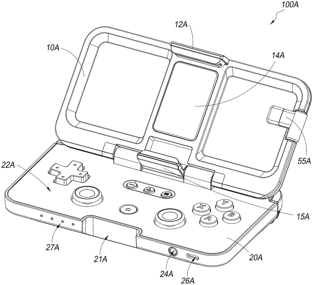
FIGS. 13-23schematically illustrates a mobile video game controller100A. Some of the features of the controller100A are similar (e.g., identical) to features of the controller100inFIGS. 1A-11. Thus, references numerals used to designate the various components of the controller100A are identical to those used for identifying the corresponding components of the controller100inFIGS. 1A-11, except that an “A” has been added to the numerical identifier. Therefore, the structure and description for the various features of the controller100inFIGS. 1A-11are understood to also apply to the corresponding features of the controller100A inFIGS. 13-23, except as described below.
The controller100A differs from the controller100in that the top panel10A pivots relative to the bottom panel20A via a single hinge40A. Additionally, the top panel10A includes an upper bracket12A and a lower bracket15A for retaining the smartphone200on the top panel10A, an a support14A (e.g., support pad) for supporting rear surface of the smartphone200. The lower bracket15A can rotate relative to the top panel10A between an extended position (seeFIG. 18) for supporting an edge of the smartphone200thereon (see e.g.,FIG. 13) and a stored position where the lower bracket15A extends at least partially into recess17A of the top panel10A, allowing the top panel10A to be rotated to the closed position relative to the bottom panel20A. The upper bracket12A is attached to a linear member13A that is slidable (e.g. slidably moves) relative to the top panel10A (seeFIG. 18) to adjust a position of the upper bracket12A relative to the lower bracket15A, allowing the controller100to advantageously couple to the smartphone200irrespective of the size (e.g., width) of the smartphone200. When the top panel10A is moved to the closed position relative to the bottom panel20A, the upper bracket12A extends into a recess21A on a front of the bottom panel20A (allowing the top panel10A to be positioned adjacent the bottom panel20A in the closed position).
With reference toFIG. 13, the lighting elements27A are on a front surface or edge of the bottom panel20A. Additionally, with reference toFIG. 21, a volume control23A is provided in the bottom panel20A for adjusting volume control (e.g., of sound coming from the smartphone200when coupled to the controller100, of sound provided to the headset via audio jack24A when the headset cable HS is connected thereto).
FIG. 14schematically illustrates a mobile video game controller100B. Some of the features of the controller100B are similar (e.g., identical) to features of the controller100A inFIGS. 13-23. Thus, references numerals used to designate the various components of the controller100B are identical to those used for identifying the corresponding components of the controller100A inFIGS. 13-23, except that a “B” has been added to the numerical identifier. Therefore, the structure and description for the various features of the controller100A inFIGS. 13-23are understood to also apply to the corresponding features of the controller100B inFIG. 24, except as described below.
The controller100B differs from the controller100A in that it further includes a power bank90A having one or more batteries. The power bank90A can deliver 5000 mAh. The power bank90A can be used to power the electronics in the controller100B to provide extended playing time using the controller100B (e.g., extend playing time by 2 to 3 times). The power bank90A can also be operated to provide power to the smartphone200(e.g., to charge the batteries of the smartphone200). For example, the power bank90A can optionally be operated to charge the smartphone200while the controller100B is operated to play a video game on the smartphone200. The controller100B has USB power delivery via the connector26A for charging the smartphone200via a cable connected to the connector26A. The controller100B also has a charging on/off switch actuatable to operate the charging of the smartphone200with the power bank90B.
ADDITIONAL EMBODIMENTS
In embodiments of the present disclosure, a mobile video game controller may be in accordance with any of the following clauses:
Clause 1. A mobile video game controller, comprising:a controller body comprisinga top panel configured to removably couple to a smartphone to support and retain the smartphone thereon irrespective of a size or shape of the smartphone, the top panel supporting a controller cable having a connector that removably couples to a power connector of the smartphone to electrically connect the controller to the smartphone;a bottom panel havinga plurality of control inputs operable to control one or more operations of a video game,a processor configured to convert one or more operations of the plurality of control inputs into electrical signals and to communicate such signals to the smartphone,an audio jack configured to receive an audio connector for a headset and configured to communicate with the processor, anda power jack configured to connect to a power source via a power cable, the processor configured to pass power from the power source through to the smartphone connected to the controller cable; anda hinge movably connecting the top panel with the bottom panel to allow the top panel to be pivoted between a closed position relative to the bottom panel and an open position relative to the bottom panel, the controller cable routed via the hinge between the top and bottom panels to electrically connect the controller cable to the processor.
Clause 2. The mobile video game controller of any preceding clause, further comprising a power bank operable to one or both of power the electronics in the bottom panel and provide power to the smartphone to charge one or more batteries of the smartphone.
Clause 3. The mobile video game controller of any preceding clause, wherein when the controller is in a closed position where the top panel is adjacent the bottom panel, the controller has a compact form factor that allows it to be stored in a pocket of a user's garment.
Clause 4. The mobile video game controller of any preceding clause, wherein at least a portion of the connector cable is integrated into the top panel.
Clause 5. The mobile video game controller of any preceding clause, wherein the open position includes a gaming mode position with the top panel oriented at an obtuse angle of greater than 90 degrees and less than 180 degrees relative to the bottom panel.
Clause 6. The mobile video game controller of any preceding clause, wherein the plurality of control inputs include one or more of a trigger, a bumper, a joystick, a directional pad, and a button.
Clause 7. The mobile video game controller of any preceding clause, further comprising a lower bracket and an upper bracket, the upper bracket adjustable relative to the lower bracket to accommodate a smartphone therebetween irrespective of a size of the smartphone.
Clause 8. The mobile video game controller of any preceding clause wherein the lower bracket is configured to rotate about an axis of the hinge relative to a surface of the top panel between an extended position and a storage position.
Clause 9. A mobile video game controller, comprising:a controller body comprisinga top panel configured to removably couple to a smartphone to support and retain the smartphone thereon between an upper bracket and a lower bracket irrespective of a size or shape of the smartphone, the top panel supporting a controller cable having a connector that removably couples to a power connector of the smartphone to electrically connect the controller to the smartphone;a bottom panel havinga plurality of control inputs operable to control one or more operations of a video game,a processor configured to convert one or more operations of the plurality of control inputs into electrical signals and to communicate such signals to the smartphone, andan audio jack configured to receive an audio connector for a headset and configured to communicate with the processor,a hinge movably connecting the top panel with the bottom panel to allow the top panel to be pivoted between a closed position relative to the bottom panel and an open position relative to the bottom panel, the controller cable routed via the hinge between the top and bottom panels to electrically connect the controller cable to the processor.
Clause 10. The mobile video game controller of any preceding clause, further comprising a power jack configured to connect to a power source via a power cable, the processor configured to pass power from the power source through to the smartphone connected to the controller cable.
Clause 11. The mobile video game controller of any preceding clause, further comprising a power bank operable to one or both of power the electronics in the bottom panel and provide power to the smartphone to charge one or more batteries of the smartphone.
Clause 12. The mobile video game controller of any preceding clause, wherein when the controller is in a closed position where the top panel is adjacent the bottom panel, the controller has a compact form factor that allows it to be stored in a pocket of a user's garment.
Clause 13. The mobile video game controller of any preceding clause, wherein at least a portion of the connector cable is integrated into the top panel.
Clause 14. The mobile video game controller of any preceding clause, wherein the open position includes a gaming mode position with the top panel oriented at an obtuse angle of greater than 90 degrees and less than 180 degrees relative to the bottom panel.
Clause 15. The mobile video game controller of any preceding clause, wherein the plurality of control inputs include one or more of a trigger, a bumper, a joystick, a directional pad, and a button.
Clause 16. The mobile video game controller of any preceding clause, wherein the upper bracket is slidable relative to the lower bracket to adjust a distance between the upper bracket and the lower bracket to accommodate the smartphone therebetween irrespective of a size of the smartphone.
Clause 17. The mobile video game controller of any preceding clause, wherein the lower bracket is configured to rotate about an axis of the hinge relative to a surface of the top panel between an extended position and a storage position.
While certain embodiments of the inventions have been described, these embodiments have been presented by way of example only, and are not intended to limit the scope of the disclosure. Indeed, the novel methods and systems described herein may be embodied in a variety of other forms. Furthermore, various omissions, substitutions and changes in the systems and methods described herein may be made without departing from the spirit of the disclosure. The accompanying claims and their equivalents are intended to cover such forms or modifications as would fall within the scope and spirit of the disclosure. Accordingly, the scope of the present inventions is defined only by reference to the appended claims.
Features, materials, characteristics, or groups described in conjunction with a particular aspect, embodiment, or example are to be understood to be applicable to any other aspect, embodiment or example described in this section or elsewhere in this specification unless incompatible therewith. All of the features disclosed in this specification (including any accompanying claims, abstract and drawings), and/or all of the steps of any method or process so disclosed, may be combined in any combination, except combinations where at least some of such features and/or steps are mutually exclusive. The protection is not restricted to the details of any foregoing embodiments. The protection extends to any novel one, or any novel combination, of the features disclosed in this specification (including any accompanying claims, abstract and drawings), or to any novel one, or any novel combination, of the steps of any method or process so disclosed.
Furthermore, certain features that are described in this disclosure in the context of separate implementations can also be implemented in combination in a single implementation. Conversely, various features that are described in the context of a single implementation can also be implemented in multiple implementations separately or in any suitable subcombination. Moreover, although features may be described above as acting in certain combinations, one or more features from a claimed combination can, in some cases, be excised from the combination, and the combination may be claimed as a subcombination or variation of a subcombination.
Moreover, while operations may be depicted in the drawings or described in the specification in a particular order, such operations need not be performed in the particular order shown or in sequential order, or that all operations be performed, to achieve desirable results. Other operations that are not depicted or described can be incorporated in the example methods and processes. For example, one or more additional operations can be performed before, after, simultaneously, or between any of the described operations. Further, the operations may be rearranged or reordered in other implementations. Those skilled in the art will appreciate that in some embodiments, the actual steps taken in the processes illustrated and/or disclosed may differ from those shown in the figures. Depending on the embodiment, certain of the steps described above may be removed, others may be added. Furthermore, the features and attributes of the specific embodiments disclosed above may be combined in different ways to form additional embodiments, all of which fall within the scope of the present disclosure. Also, the separation of various system components in the implementations described above should not be understood as requiring such separation in all implementations, and it should be understood that the described components and systems can generally be integrated together in a single product or packaged into multiple products.
For purposes of this disclosure, certain aspects, advantages, and novel features are described herein. Not necessarily all such advantages may be achieved in accordance with any particular embodiment. Thus, for example, those skilled in the art will recognize that the disclosure may be embodied or carried out in a manner that achieves one advantage or a group of advantages as taught herein without necessarily achieving other advantages as may be taught or suggested herein.
Conditional language, such as “can,” “could,” “might,” or “may,” unless specifically stated otherwise, or otherwise understood within the context as used, is generally intended to convey that certain embodiments include, while other embodiments do not include, certain features, elements, and/or steps. Thus, such conditional language is not generally intended to imply that features, elements, and/or steps are in any way required for one or more embodiments or that one or more embodiments necessarily include logic for deciding, with or without user input or prompting, whether these features, elements, and/or steps are included or are to be performed in any particular embodiment.
Conjunctive language such as the phrase “at least one of X, Y, and Z,” unless specifically stated otherwise, is otherwise understood with the context as used in general to convey that an item, term, etc. may be either X, Y, or Z. Thus, such conjunctive language is not generally intended to imply that certain embodiments require the presence of at least one of X, at least one of Y, and at least one of Z.
Language of degree used herein, such as the terms “approximately,” “about,” “generally,” and “substantially” as used herein represent a value, amount, or characteristic close to the stated value, amount, or characteristic that still performs a desired function or achieves a desired result. For example, the terms “approximately”, “about”, “generally,” and “substantially” may refer to an amount that is within less than 10% of, within less than 5% of, within less than 1% of, within less than 0.1% of, and within less than 0.01% of the stated amount. As another example, in certain embodiments, the terms “generally parallel” and “substantially parallel” refer to a value, amount, or characteristic that departs from exactly parallel by less than or equal to 15 degrees, 10 degrees, 5 degrees, 3 degrees, 1 degree, or 0.1 degree.
The scope of the present disclosure is not intended to be limited by the specific disclosures of preferred embodiments in this section or elsewhere in this specification, and may be defined by claims as presented in this section or elsewhere in this specification or as presented in the future. The language of the claims is to be interpreted broadly based on the language employed in the claims and not limited to the examples described in the present specification or during the prosecution of the application, which examples are to be construed as non-exclusive.
Of course, the foregoing description is that of certain features, aspects and advantages of the present invention, to which various changes and modifications can be made without departing from the spirit and scope of the present invention. Moreover, the invention need not feature all of the objects, advantages, features and aspects discussed above. Thus, for example, those of skill in the art will recognize that the invention can be embodied or carried out in a manner that achieves or optimizes one advantage or a group of advantages as taught herein without necessarily achieving other objects or advantages as may be taught or suggested herein. In addition, while a number of variations of the invention have been shown and described in detail, other modifications and methods of use, which are within the scope of this invention, will be readily apparent to those of skill in the art based upon this disclosure. It is contemplated that various combinations or subcombinations of these specific features and aspects of embodiments may be made and still fall within the scope of the invention. Accordingly, it should be understood that various features and aspects of the disclosed embodiments can be combined with or substituted for one another in order to form varying modes of the discussed controllers.
Claims
- A mobile video game controller, comprising: a controller body comprising a top panel configured to removably couple to a smartphone to support and retain the smartphone thereon between an upper bracket and a lower bracket, the top panel supporting a controller cable having a connector that removably couples to a power connector of the smartphone to electrically connect the controller to the smartphone;a bottom panel having a plurality of control inputs operable to control one or more operations of a video game, a processor configured to convert one or more operations of the plurality of control inputs into electrical signals and to communicate such signals to the smartphone, and a power jack configured to connect to a power source via a power cable, the processor configured to pass power from the power source through to the smartphone connected to the controller cable;and a hinge movably connecting the top panel with the bottom panel to allow the top panel to be pivoted between a closed position relative to the bottom panel and an open position relative to the bottom panel, the lower bracket being configured to rotate relative to the upper bracket and configured to rotate about an axis of the hinge relative to a surface of the top panel between an extended position and a storage position, the controller cable routed via the hinge between the top and bottom panels to electrically connect the controller cable to the processor.
- The mobile video game controller of claim 1, further comprising a power bank operable to one or both of power electronics in the bottom panel and provide power to the smartphone to charge one or more batteries of the smartphone.
- The mobile video game controller of claim 1, wherein when the controller is in a closed position where the top panel is adjacent the bottom panel, the controller has a compact form factor that allows it to be stored in a pocket of a user's garment.
- The mobile video game controller of claim 1, wherein at least a portion of the connector cable is integrated into the top panel.
- The mobile video game controller of claim 1, wherein the open position includes a gaming mode position with the top panel oriented at an obtuse angle of greater than 90 degrees and less than 180 degrees relative to the bottom panel.
- The mobile video game controller of claim 1, wherein the plurality of control inputs include one or more of a trigger, a bumper, a joystick, a directional pad, and a button.
- The mobile video game controller of claim 1, wherein the upper bracket is adjustable relative to the lower bracket to accommodate a smartphone therebetween irrespective of a size of the smartphone.
- A mobile video game controller, comprising: a controller body comprising a top panel configured to removably couple to a smartphone to support and retain the smartphone thereon between an upper bracket and a lower bracket irrespective of a size or shape of the smartphone, the upper bracket is slidable relative to the lower bracket to adjust a distance between the upper bracket and the lower bracket to accommodate the smartphone therebetween irrespective of a size of the smartphone, the top panel supporting a controller cable having a connector that removably couples to a power connector of the smartphone to electrically connect the controller to the smartphone;a bottom panel having a plurality of control inputs operable to control one or more operations of a video game, and a processor configured to convert one or more operations of the plurality of control inputs into electrical signals and to communicate such signals to the smartphone, a hinge movably connecting the top panel with the bottom panel to allow the top panel to be pivoted between a closed position relative to the bottom panel and an open position relative to the bottom panel, the lower bracket being configured to rotate relative to the upper bracket and configured to rotate about an axis of the hinge relative to a surface of the top panel between an extended position and a storage position, the controller cable routed via the hinge between the top and bottom panels to electrically connect the controller cable to the processor.
- The mobile video game controller of claim 8, further comprising a power jack configured to connect to a power source via a power cable, the processor configured to pass power from the power source through to the smartphone connected to the controller cable.
- The mobile video game controller of claim 8, further comprising a power bank operable to one or both of power electronics in the bottom panel and provide power to the smartphone to charge one or more batteries of the smartphone.
- The mobile video game controller of claim 8, wherein when the controller is in a closed position where the top panel is adjacent the bottom panel, the controller has a compact form factor that allows it to be stored in a pocket of a user's garment.
- The mobile video game controller of claim 8, wherein at least a portion of the connector cable is integrated into the top panel.
- The mobile video game controller of claim 8, wherein the open position includes a gaming mode position with the top panel oriented at an obtuse angle of greater than 90 degrees and less than 180 degrees relative to the bottom panel.
- The mobile video game controller of claim 8, wherein the plurality of control inputs include one or more of a trigger, a bumper, a joystick, a directional pad, and a button.
Disclaimer: Data collected from the USPTO and may be malformed, incomplete, and/or otherwise inaccurate.