U.S. Pat. No. 11,471,755
Process For The Enhancements and Modifications Of A Stock Video Game Controller
Issue DateMay 17, 2019
Illustrative Figure
Abstract
Enhancements to existing gaming controllers facilitating expedient response time and fine-tuned accuracy are described. The enhancements comprise the internal modification of the stock resistance force supplied by the analog stick centering spring mechanism. Through modification, the force of resistance supplied may be increased to over 200 grams of force, or down to 40 grams of force, while maintaining full function of the analog stick mechanism. A second primary enhancement replaces the stock triggers, conventionally equipped with progressive resistance sensors, to a momentary ‘snap-action’ two-way switch, minimizing trigger pull distance, and removing the analog nature of the trigger to achieve optimal performance.
Description
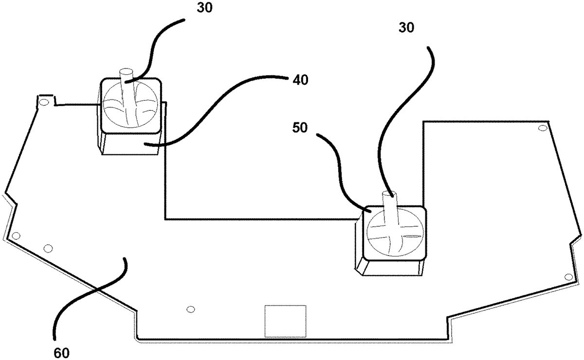
DETAILED DESCRIPTION OF THE PREFERRED EMBODIMENT The present invention generally comprises a series of modifications made to a stock gaming controller configured to facilitate and enhance gameplay by minimizing the tactile response time of the buttons and increasing the resistance, and ultimately the accuracy, of the analog stick controls. The present invention primarily employs a ‘snap-action’ switch (10) (or snap switch) to increase the responsiveness of stock trigger buttons, as well as a spring replacement (20) to alter the stock tension of the analog sticks. The ‘snap-action’ switch (10) includes two primary components: a trigger equipped with a magnet (15) shown inFIG. 3, and a switch module (45) as shown inFIG. 7. The Lever Return force or Return-to-Center force, often referred to as the analog stick tension, is modified by the enhancements of the present invention. The analog stick tension or resistance force should be understood as the amount of mechanical force the device exerts to either return to center, or resistance to be moved from a center position to an exterior movement. The process of altering the analog stick tension includes several steps to achieve the desired enhancement. First, the stock controller unit is disassembled, and the main electronic boards are removed. (100) This includes the removal of the control board (60) for the controller from the outer casing of the controller. After removal, the control stick modules (40) are exposed. Once the rear of the control board (60) is accessible, the conventional14solder points that secure the through-hole component to the board may be removed. (110) The solder can be removed by adding lead solder to the solder points, and then using a desolder tool to free the control stick modules (40) from the control board. Once removed, the unit is further disassembled by prying up the four retaining ...
DETAILED DESCRIPTION OF THE PREFERRED EMBODIMENT
The present invention generally comprises a series of modifications made to a stock gaming controller configured to facilitate and enhance gameplay by minimizing the tactile response time of the buttons and increasing the resistance, and ultimately the accuracy, of the analog stick controls. The present invention primarily employs a ‘snap-action’ switch (10) (or snap switch) to increase the responsiveness of stock trigger buttons, as well as a spring replacement (20) to alter the stock tension of the analog sticks. The ‘snap-action’ switch (10) includes two primary components: a trigger equipped with a magnet (15) shown inFIG. 3, and a switch module (45) as shown inFIG. 7.
The Lever Return force or Return-to-Center force, often referred to as the analog stick tension, is modified by the enhancements of the present invention. The analog stick tension or resistance force should be understood as the amount of mechanical force the device exerts to either return to center, or resistance to be moved from a center position to an exterior movement.
The process of altering the analog stick tension includes several steps to achieve the desired enhancement. First, the stock controller unit is disassembled, and the main electronic boards are removed. (100) This includes the removal of the control board (60) for the controller from the outer casing of the controller. After removal, the control stick modules (40) are exposed. Once the rear of the control board (60) is accessible, the conventional14solder points that secure the through-hole component to the board may be removed. (110) The solder can be removed by adding lead solder to the solder points, and then using a desolder tool to free the control stick modules (40) from the control board. Once removed, the unit is further disassembled by prying up the four retaining clips present on the bottom of the control stick assembly (40) to release the plastic bottom base (25) of the control stick assembly (40). (120) When removed, the lever return mechanism is exposed. (130). The lever return mechanism is conventionally comprised of four main parts: a domed base in the center, a plastic circular plunger (35) disposed on the base configured to center on the domed portion, and a spring disposed atop the plunger and nestled within the main assembly (pin) of the analog stick. The stock spring disposed atop the plunger is removed. (140). Next, the spring replacement (20) is installed in the position of the stock spring. (150)
When the pin of the analog stick is pushed in a direction away from center, the plunger pushes in against the spring to create force, and when released, the analog stick returns to the center, neutral position. The present invention implements a spring replacement (20) configured to accurately increase the return center tension from the traditional 65 grams of force to 110 grams of force. With minor adjustments, the spring replacement (20) can provide additional tension between 160 grams of force to 210 grams of force, broadening the customization options of the player, and yielding more accurate gameplay. Other embodiments of the present invention configured to reduce the return tensions employ the factory spring, modified via compression, causing the spring-supplied return force to be deployed later in the cycle, thus bringing the tension down to about 40 grams force. Optionally, a replacement stick-click button may be installed to replace the stock stick-click button disposed at the center axis of each control stick assembly. The replacement of the stock stick-click button with a replacement stick-click button may be required to maintain the unmuffled ‘click’ sound which occurs when the control stick is pressed down on the central axis of the control stick. The replacement stick-click button preferably requires 20 g of force to activate and create the audible ‘click’ sound, preventing the muffled sound.
Once the desired spring is replaced, the plunger and spring are inserted into the main assembly, and the base is reattached. (160) A light film of glue may be used to reaffix the clips on the base (25). With the updated control stick assembly (40) fully assembled, it can then be re-installed onto the board. (170) During installation, the proper alignment of the 2 directional potentiometers and the tactile button must be maintained. (180) The tactile button is installed flush, then the outside two farthest pins' solder is heated up and then pushed so it sits at a slight angle for optimal performance. (190)
The benefit of the enhanced analog stick tension provided by the process of the present invention is that it provides the users the option of increased or decreased resistance feedback from the analog stick mechanism. When the user is using various heights of analog stick caps, the tension adjustment will compensate for force lost by the use of a taller cap.
The second portion of the adjustments to gaming controllers is performed on the trigger assembly themselves. On a controller that has a linear potentiometer, Linear Hall Effect, or other progressive resistance sensor the user will experience different trigger values at different trigger pulls. Similar to the gas pedal in a vehicle, as it is pressed harder, the vehicle moves at an increased speed. The sensor, electronically will register a different voltage output based on position. Not all users prefer to have a progressive sensor in their gaming hardware. Where in some instances, the amount of travel may be 8-12 mm to register from 0% to 100% trigger pull.
The enhancements of the present invention are comprised of several steps to replace the conventional linear system with that of a momentary snap-action switch. The snap-action switch of the preferred embodiment of the present invention is configured to replace the stock progressive-type sensor with a two-way snap-action circuit switch. The snap-action switch is a critical portion of the enhancement; yet, in order to ensure that it functions properly, several other components are employed. The snap-action switch is positioned at a pre-determined height and angle depending on the stock controller supplied for modification. For example the Xbox One™ stock controller employs a Linear Hall Effect sensor that is soldered onto the back of the main logic board. The Linear Hall Effect sensor has a magnet attached to the rear chassis of the trigger assembly. As the trigger is pulled, the magnet moves closer to the Linear Hall Effect sensor, and provides varying resistance.
The switch module (45) snap-action switch (10) of the present invention is preferably disposed above the existing hall sensor and soldered into place as shown inFIG. 7. (200) The proper angle and height is determined prior to installation according to the model and manufacturer of the controller. (210) The portion that contacts the button on the switch is the flat side of an original magnet (15) of the original trigger switch. The supplemental magnet is held onto the controller with heat shrink tubing, which is installed, and is soft to the touch. (220) To provide a wear area, a small 7 mm by 7 mm piece of stainless steel is affixed to the heat shrink tube. (230) As the trigger moves, the stainless pad will press and depress the switch. On the outer cap of the trigger is a lip that has a small piece of foam. The foam is configured to serve as a buffer between the trigger during its return cycle and the lower housing assembly. The foam buffer is removed and is replaced with a 1.5 mm rubber pad. (240) The rubber pad is then shaved down to allow the trigger to fully return to center while depressing the switch. (250) This creates a specific amount of space to make the trigger function like a button with the tactical feedback of a mouse click. (260)
The player then preferably employs this modification to accomplish two things: firstly, this enhancement of the present invention provides a significantly shorter trigger pull distance, set initially between 8-12 mm, down to about 0.5-2 mm distance. Due to the shorter distance the trigger is required to travel to reach 100% action on the switch, the user can input the function at a quicker pace. Then instead of simply limiting the trigger pull, the snap-action switch (10), when pressed, creates a circuit that registers at full resistance, mimicking 100% of the trigger pull. Within the 0.5-2 mm trigger pull the user experiences the same beginning and ending function as the original without the longer pull and without the linear ramp up needed to achieve full power on the stock switch.
The technical specifications of the preferred embodiment of the spring replacement (20) of the present invention are roughly as follows:
Solid Length:0.1140in.Solid Load:2.667LbfSolid Stress:157760Lbf/in{circumflex over ( )}2Stress Factor:1.216Active Coils:3.000Spring Index:6.895Helix Angle:7.064DegreesSpring Pitch:0.05100in.Inside Diameter:0.1120in.Mean Coil Diameter:0.1310in.Wire Length:2.068in.Weight/1000:0.1665LbNatural Frequency:311712RPMWire Diameter:0.01900in.Outside Diameter:0.1500in.Total Coils:5.0Spring Rate:27.777Lbf/in (calculated)Free Length:0.2100in.Length (in operation):0.1567Load (in operation):1.481Deflection:0.05330Stress87590Outer Diameter Expansion:0.0007432
It should be noted thatFIG. 9depicts a view of the two instances of the non-stock switch (10), shown adjacent to corresponding striking surfaces (270) and stock shoulder buttons (280).FIG. 8exhibits an isolated view of a rubber contact pad (290) of the present invention.
It should be understood that the process of implementation of the enhancements of the present invention may vary slightly between popular gaming controllers for differently branded gaming consoles. In the current instantiation and generation of gaming controllers for gaming consoles and computers, the process of implementation is largely the same across manufacturers.
Having illustrated the present invention, it should be understood that various adjustments and versions might be implemented without venturing away from the essence of the present invention. Further, it should be understood that the present invention is not solely limited to the invention as described in the embodiments above, but further comprises any and all embodiments within the scope of this application.
The foregoing descriptions of specific embodiments of the present invention have been presented for purposes of illustration and description. They are not intended to be exhaustive or to limit the present invention to the precise forms disclosed, and obviously many modifications and variations are possible in light of the above teaching. The exemplary embodiment was chosen and described in order to best explain the principles of the present invention and its practical application, to thereby enable others skilled in the art to best utilize the present invention and various embodiments with various modifications as are suited to the particular use contemplated.
Claims
- A process for the enhancement and modification of a stock video game controller comprising: disassembling a housing of the controller;replacing any and all stock progressive-type sensors with two-way snap-action circuit switches;installing heat shrink tubings to supplemental magnets to hold the supplemental magnets onto the controller;affixing wear areas to the heat shrink tubings;and replacing foam buffers with rubber pads, and then shaving the rubber pads to allow triggers to fully return to center while depressing the two-way snap-action circuit switches.
- The method of claim 1, further comprising: connecting the two-way snap-action circuit switches to a mainboard of the controller.
- The method of claim 1, wherein the two-way snap-action circuit switches are tactile buttons.
- The method of claim 1, wherein the rubber pad is 1.5 mm thick.
Disclaimer: Data collected from the USPTO and may be malformed, incomplete, and/or otherwise inaccurate.