Illustrative Figure
Abstract
A game controller according to the present disclosure includes: a housing; and an internal structural body accommodated inside of the housing. The internal structural body includes at least: an internal frame having an installation surface and a recess adjacent to the installation surface; a battery that is accommodated in the recess of the internal frame and has a first surface that opposes a bottom surface of the recess and a second surface on a side opposite to that of the first surface; and a flexible substrate that is installed on the installation surface of the internal frame and includes a conductive pattern. The flexible substrate is arranged so as to cover at least a portion of the second surface of the battery accommodated in the recess.
Description
EMBODIMENTS Hereinafter, an embodiment of the game controller according to the present disclosure will be described with reference to the drawings. Hereinafter, for the sake of convenience in the description, description will be given in accordance with the directions shown in the drawings. However, there is no limitation to these directions in the production of the game controller according to the present disclosure. 1. Overview of Game Controller FIG. 1is a perspective view of a game controller according to the present embodiment,FIG. 2is a perspective view of an upper cover,FIG. 3is a perspective view of a lower cover, andFIG. 4is a perspective view of an internal structural body. As shown inFIGS. 1 to 4, the game controller according to the present embodiment includes a housing1and an internal structural body2that is accommodated in the housing1. Furthermore, a vibrator31for providing vibration to the housing1is accommodated in the housing1(seeFIG. 5). The housing1is constituted by an upper cover11and a lower cover12, and the internal structural body2and the vibrator31are accommodated in the internal space surrounded by the upper cover11and the lower cover12. In addition, a main substrate (seeFIG. 10), multiple operation buttons41to45, and the like (operation members) are attached to the upper cover11, and the lower cover12is provided with an extended portion122accommodating the vibrator31. Hereinafter, the members will be described in detail. 2. Internal Structural Body First, the internal structural body will be described with reference toFIG. 5as well.FIG. 5is an exploded perspective view of the internal structural body. As shown inFIGS. 4 and 5, the internal structural body2includes an internal frame5, a flexible substrate7that is attached to the internal frame5, and a battery9that is accommodated in the internal frame5. Also, an R button41and an L button42are respectively attached to the right end portion and the left end portion of the front portion of the ...
EMBODIMENTS
Hereinafter, an embodiment of the game controller according to the present disclosure will be described with reference to the drawings. Hereinafter, for the sake of convenience in the description, description will be given in accordance with the directions shown in the drawings. However, there is no limitation to these directions in the production of the game controller according to the present disclosure.
1. Overview of Game Controller
FIG. 1is a perspective view of a game controller according to the present embodiment,FIG. 2is a perspective view of an upper cover,FIG. 3is a perspective view of a lower cover, andFIG. 4is a perspective view of an internal structural body. As shown inFIGS. 1 to 4, the game controller according to the present embodiment includes a housing1and an internal structural body2that is accommodated in the housing1. Furthermore, a vibrator31for providing vibration to the housing1is accommodated in the housing1(seeFIG. 5). The housing1is constituted by an upper cover11and a lower cover12, and the internal structural body2and the vibrator31are accommodated in the internal space surrounded by the upper cover11and the lower cover12. In addition, a main substrate (seeFIG. 10), multiple operation buttons41to45, and the like (operation members) are attached to the upper cover11, and the lower cover12is provided with an extended portion122accommodating the vibrator31. Hereinafter, the members will be described in detail.
2. Internal Structural Body
First, the internal structural body will be described with reference toFIG. 5as well.FIG. 5is an exploded perspective view of the internal structural body. As shown inFIGS. 4 and 5, the internal structural body2includes an internal frame5, a flexible substrate7that is attached to the internal frame5, and a battery9that is accommodated in the internal frame5. Also, an R button41and an L button42are respectively attached to the right end portion and the left end portion of the front portion of the internal frame5. Furthermore, conductive rubbers411and421are respectively attached to the R button41and the L button42. Hereinafter, the members will be described. Note that the following is an example of the internal structural body2, and components and the like other than the members indicated hereinafter can be provided as appropriate.
2-1. Internal Frame
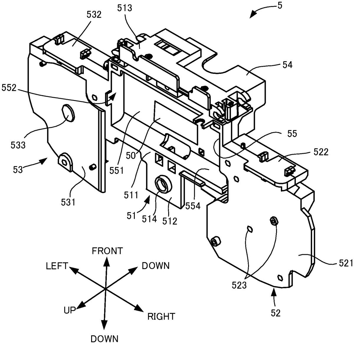
Next, an internal frame will be described with reference toFIGS. 6 to 8as well.FIG. 6is a perspective view of the internal frame,FIG. 7is a partial perspective view of the internal frame accommodating a battery, andFIG. 8is a cross-sectional view taken along line A-A inFIG. 7. As shown inFIGS. 6 and 7, the internal frame5includes a center portion51, a right portion52that is arranged on the right side of the center portion51, and a left portion53that is arranged on the left side of the center portion51, and the flexible substrate7is mainly supported by the upper surfaces thereof. Furthermore, a support portion54that supports the vibrator31is provided on the lower surface side of the center portion51. The center portion51includes an accommodating portion511that is rectangular in a plan view, and a protruding portion512that is rectangular in a plan view and protrudes from the rear end of the accommodating portion511. A rectangular recess55is formed spanning over approximately the entirety on the upper surface of the accommodating portion511, and a battery9with a flat shape is accommodated in the recess55. The battery9is formed into an approximate cuboid shape, and has a front end surface91and a rear end surface92that are formed into circular arc shapes in cross section so as to protrude toward the outside. Also, as shown inFIG. 5, a cable98for connecting to a later-described main substrate32is provided on the right-side surface of the battery9.
As shown inFIGS. 6 to 8, the recess55is constituted by a rectangular flat bottom wall portion (bottom surface)551and a side wall portion552that stands upright from the peripheral edge of the bottom wall portion551. The joining portions at which the front-side surface553and the bottom wall surface551are joined in the four surfaces forming the side wall portion552are formed into circular arc shapes in cross section so as to correspond to the front end surface91of the battery9. Similarly, the joining portions at which the rear-side surface554and the bottom wall portion551are joined in the side wall portion552are formed into circular arc shapes in cross section so as to correspond to the rear end surface92of the battery9.
Also, rectangular retaining portions (restricting members)555are provided on the side wall portion552so as to cover the vicinities of the left and right corner portions on the front side of the recess55. The retaining portions555are formed into plate shapes and the upper surfaces thereof are level with the upper surface of the accommodating portion511. Also, the front end portion of the battery9is accommodated in the gap between the retaining portions555and the bottom wall portion551.
The length in the front-rear direction and the length in the left-right direction of the recess55are respectively formed slightly greater than the length in the front-rear direction and the length in the left-right direction of the battery9, and when the battery9is accommodated in the recess55, a small clearance is formed between the battery9and the side wall portion552(e.g., within 1 mm). On the other hand, as shown inFIG. 8, the height of the battery9is approximately the same as the distance between the above-described retaining portion555and the bottom wall portion551. Accordingly, the depth of the recess55, that is, a height (first height) H1of the side wall portion552, is approximately higher than the height of the battery9by approximately the thickness of the retaining portions555. For this reason, when the battery9is accommodated in the recess55, the upper surface93of the battery9is located slightly below the upper end portion of the side wall portion552. That is, a height H2(second height) from the bottom wall portion551to the upper surface93(second surface) of the accommodated battery9is smaller than the height H1(first height) of the side wall portion552. Furthermore, as shown inFIG. 6, double-sided tape50is arranged on the bottom wall portion551, and the bottom wall portion551and the lower surface (first surface) of the battery9are fixed to each other by the double-sided tape50.
Also, as shown inFIGS. 4 and 6, the R button41is attached to the right end portion of the front end surface513of the center portion51. The R button41is a button that extends in the left-right direction, and the left end portion thereof is swingably joined to the right end portion of the front end surface513. On the other hand, the L button42is attached to the left end portion of the front end surface513. The L button42is also a button that extends in the left-right direction and the right end portion thereof is swingably joined to the left end portion of the front end surface513.
The width in the left-right direction of the protruding portion512is smaller than the width of the accommodating portion511, and the protruding portion512protrudes rearward from near the center of the rear end of the accommodating portion511. A circular protrusion514is formed on the upper surface of the protruding portion512, and is used for positioning when attaching the flexible substrate7to the internal frame5.
Next, the right portion52will be described. As shown inFIG. 6, the right portion52includes a main body portion521that is formed into a plate shape that is approximately rectangular in a plan view, and a plate-shaped front surface portion522that is joined so as to extend downward from the front end of the main body portion521. The front end of the main body portion521is located slightly rearward relative to the front end surface513of the center portion51, and the rear end of the main body portion521is located even further rearward than the rear end of the protruding portion512. Also, a gap is formed between the main body portion521and the protruding portion512in the left-right direction. Also, the upper surface (installation surface, first support surface) of the main body portion521extends so as to be continuous from the right end portion of the upper surface of the accommodating portion511, and the two upper surfaces are approximately level. Furthermore, multiple circular protrusions523are formed on the upper surface of the main body portion521, and are used for positioning when attaching the flexible substrate7to the internal frame5.
The front surface portion522extends spanning over approximately the entirety in the left-right direction of the front end of the main body portion521. Since the front surface portion522is located rearward with respect to the front end surface513of the center portion51, a level difference is formed between the center portion51and the front surface portion522, and the R button41is arranged so as to fill in this level difference. To give a more specific description, as shown inFIG. 4, the R button41is attached to the front end surface522of the right portion52via the conductive rubber411.
Next, the left portion53will be described. As shown inFIG. 6, the left portion53includes a main body portion531that is formed into a plate shape that is approximately rectangular in a plan view, and a plate-shaped front surface portion532that is joined so as to extend downward from the front end of the main body portion531. The front end of the main body portion531is located slightly rearward relative to the front end surface513of the center portion51, and the rear end of the main body portion531is located even further rearward than the rear end of the protruding portion512. Also, a gap is formed between the main body portion531and the protruding portion512in the left-right direction. Also, the upper surface (installation surface, second support surface) of the main body portion531extends so as to be continuous from the left end portion of the upper surface of the accommodating portion511, but is joined in an oblique manner so as to incline slightly downward as the left side is approached. Furthermore, a circular protrusion533is formed on the upper surface of the main body portion531, and is used for positioning when attaching the flexible substrate7to the internal frame5.
The front surface portion532extends spanning over approximately the entirety in the left-right direction of the front end of the main body portion531. Since the front surface portion532is located rearward relative to the front end surface513of the center portion51, a level difference is formed between the accommodating portion511and the front surface portion532, and the L button42is arranged so as to fill in the level difference. To give a more specific description, as shown inFIG. 4, the L button42is attached to the front end surface532of the left portion53via the conductive rubber421.
Next, the support portion54will be described. As shown inFIG. 6, a recess that opens downward is formed in the support portion54, and multiple support plates (not shown) whose lower end portions are formed into circular arc shapes that protrude upward are arranged inside of the recess. Also, a circular column-shaped vibrator31is accommodated in the recess. That is, approximately half of the vibrator is accommodated in the recess such that the outer peripheral surface of the vibrator31comes into contact with the support plates. Accordingly, approximately half of the vibrator31is exposed to the outside from the support portion54.
Although there is no particular limitation on the configuration of the vibrator31, for example, it is possible to include a vibration motor and generate predetermined vibration using the vibration motor. For example, it is possible to cause the vibration motor to vibrate at an amplitude and a frequency that correspond to the waveform of an input voltage.
2-2. Flexible Substrate
Next, the flexible substrate7will be described with reference toFIG. 9as well.FIG. 9is a perspective view of a flexible substrate. As shown inFIG. 9, the flexible substrate7is a known flexible printed circuit board (FPC) obtained by implementing predetermined wiring on a base film, and includes a center portion71, a rear portion72, a right portion73, a left portion74, a right-front portion75, and a left-front portion76, and these portions are formed in one piece. Hereinafter, the portions will be described.
The center portion71is a portion that is arranged spanning over the entirety in the left-right direction on the upper surface of the accommodating portion511of the internal frame5, and is formed into a band shape that extends in the left-right direction. To give a more specific description, the center portion71is arranged so as to cover the upper surface of the battery9accommodated in the recess55of the accommodating portion511. As described above, a gap is formed between the upper surface93of the battery9and the upper end of the side wall portion552, and therefore a gap is formed between the center portion71and the battery9as well. Also, in the present embodiment, as one example, the center portion71may be arranged so as to cover the half of the battery9that is located rearward with respect to the center of the upper surface93thereof instead of covering the entirety of the battery9. Note that the length in the left-right direction of the center portion71is slightly longer than the accommodating portion511.
The rear portion72is a rectangular portion that is joined to the rear end of the center portion71, and is arranged on the upper surface of the protruding portion512of the internal frame5. A circular through hole721is formed on the rear portion72, and the protrusion514of the protruding portion512fits therein.
Next, the right portion73will be described. The right portion73is joined to the right side of the center portion71and is arranged on the upper surface of the right portion52of the internal frame5. Multiple through holes731are formed in the right portion73, and the protrusions523formed on the upper surface of the right portion52are fit therein. Also, multiple contacts (not shown) are arranged on the upper surface of the right portion73, and these contacts are electrically connected by conductive rubbers115(seeFIG. 10) for the four operation buttons arranged on the right side of the later-described upper cover11.
Next, the right-front portion75will be described. The right-front portion75is a portion that is joined to the front end of the right portion73, is folded along the joining portion at which the main body portion521and the front surface portion522of the right portion52of the internal frame5are joined to each other, and is arranged on the front surface portion522. A contact (not shown) for the R button41is arranged on the right-front portion75, and the conductive rubber411is arranged so as to cover the contact. The conductive rubber411is fixed to a protrusion (not shown) formed on the front surface portion522, and when the conductive rubber411is pressed by the R button41, the conductive rubber411causes electrical conduction in the contact of the right-front portion75.
Next, the left-front portion76will be described. The left-front portion76is a portion that extends frontward from the left-front end portion of the center portion71, and includes a first portion761that is arranged on the main body portion531of the left portion53of the internal frame5, and a second portion762that is folded along the joining portion at which the main body portion531and the front surface portion532are joined, and that is arranged on the front surface portion532. A contact (not shown) for the L button42is arranged on the second portion762, and the conductive rubber421is arranged so as to cover this contact. The conductive rubber421is fixed to a protrusion (not shown) formed on the front surface portion532, and when the conductive rubber421is pressed by the L button42, the conductive rubber421causes electrical conduction in the contact of the second portion762.
Next, the left portion74will be described. The left portion74is joined to the left side of the center portion71and is arranged on the upper surface of the left portion53of the internal frame5. A through hole741is formed near the center of the left portion74, and the protrusion533formed on the upper surface of the left portion53is fit therein. Also, as described above, the left portion53of the internal frame5is joined so as to be inclined with respect to the center portion51, and therefore the left portion74is folded slightly obliquely with respect to the center portion71and is arranged so as to extend along the upper surface of the left portion53. Furthermore, multiple contacts (not shown) are arranged on the upper surface of the left portion74, and these contacts are electrically connected by conductive rubbers116(seeFIG. 10) for a D-pad49arranged on the left side of the later-described upper cover11.
3. Upper Cover and Main Substrate
Next, an upper cover will be described with reference toFIGS. 10 and 11as well.FIG. 10is a perspective view from below of a main substrate and an upper cover to which the conductive rubber is attached, andFIG. 11is a schematic view showing a partial cross-section of the left side of the controller. As shown inFIG. 2, the upper cover11is formed into a cup shape so as to cover the upper side of the internal structural body2, and is formed into an oval shape in a plan view that extends in the left-right direction. Four operation buttons41to44are arranged on the right side of the upper cover11, and the D-pad45is arranged on the left side. The right side of the upper cover11is a portion that corresponds to the right portion73of the flexible substrate7, four circular through holes are formed therein, and the operation buttons41to44are fit into the respective through holes so as to be able to move up and down. Also, the conductive rubbers115that are accommodated inside of the upper cover11are attached to the lower end portions of the operation buttons41to44, and when the operation buttons41to44are pressed, as described above, the conductive rubbers115cause electrical conduction in the contacts of the right portion73of the flexible substrate7.
As shown inFIG. 11, the left side of the upper cover11is a portion corresponding to the left portion74of the flexible substrate7, and is formed so as to extend slightly obliquely from near the center. Accordingly, the left side portion113of the upper cover11and the left portion74of the flexible substrate7are approximately parallel to each other. A cross-shaped through hole is formed on the left-side portion113, and the D-pad45is fit into this through hole. Accordingly, the D-pad45is also arranged approximately parallel to the left portion74of the flexible substrate7. Note that inFIG. 11, the inclinations of the upper cover11and the like are illustrated in an exaggerated manner in order to facilitate comprehension.
The D-pad45is configured such that its four end portions swing with respect to the center, and a conductive rubber116having conductive portions116ato116dis attached to the lower end portions of the end portions. Also, when any end portion of the D-pad45is pressed in, as described above, the conductive portions116ato116dcause electrical conduction in the contacts of the left portion74. Note that electrical conduction can also be caused in two contacts at the same time by pressing any two adjacent end portions among the four end portions of the D-pad45at the same time.
Notches117and118are formed on both sides of the front end of the upper cover11, and these notches117and118are combined with notches125and126in the later-described lower cover12to form through holes. Also, the R button41and the L button42are exposed from these through holes.
As shown inFIG. 10, the main substrate32is fixed to the lower surface near the center of the upper cover11. The main substrate32is constituted by a hard printed circuit board, and is equipped with electrical components such as an operation control circuit, a communication module, an NFC circuit, a power source control circuit, and multiple terminals, which are not shown in the drawings. When various operation buttons and the like are pressed, the operation control circuit generates operation data corresponding thereto. The thus-generated operation data is transmitted to a game device main body by the communication module. The NFC circuit performs near-field wireless communication based on the NFC standard, and performs transmission and reception of operation data and the like through wireless communication between the game controller and the game device main body. The power source control circuit performs drive control of the battery. Furthermore, cables (not shown) that respectively extend from the battery9, the flexible substrate7, and the vibrator31are connected to the terminals of the main substrate32. Note that when the internal structural body2is attached to the upper cover11, a gap is formed between the main substrate32and the flexible substrate7, and the main substrate32and the flexible substrate7are prevented from coming into contact with each other.
4. Lower Cover
As shown inFIG. 3, the lower cover12is formed so as to cover the lower side of the internal structural body2, and includes a cup-shaped cover main body121that extends in the left-right direction and is formed into an oval shape in plan view so as to correspond to the upper cover11, and an extended portion122that extends downward from near the center of the front end of the cover main body121, and these portions are formed in one piece. The extended portion122accommodates the support portion54and the vibrator31of the internal frame5, and is formed into a cuboid shape.
Notches125and126are formed on both sides of the extended portion122in the cover main body121, and as described above, are combined with the notches117and118of the upper cover11to form the through holes.
5. Method for Assembling Game Controller
Next, an example of a method for assembling the components relating to the present disclosure in the game controller constituted as described above will be described with reference toFIGS. 12 and 13as well.FIGS. 12 and 13are perspective views for illustrating assembly of the game controller.
First, as shown inFIG. 6, the double-sided tape61is fixed to the recess55of the accommodating portion511of the internal frame5. Next, the battery9is accommodated in the recess55. First, as shown inFIG. 12, the front end surface91of the battery9is inserted between the bottom wall portion551and the retaining portions555of the recess55in a state in which the front end surface91is inclined downward toward the internal frame5. In this state, the rear portion of the battery9is pivoted downward centered about the front end surface91of the battery9and the battery9is accommodated in the recess55. The cable98of the battery9is passed through a groove556formed on the right side of the recess55, and is pulled upward from the gap between the protruding portion512and the right portion52via the lower surface of the internal frame5from the groove556. In this manner, the lower surface of the battery9is fixed to the bottom wall portion551of the recessed portion55by the double-sided tape50.
Next, as shown inFIG. 13, the flexible substrate7is fixed to the internal frame5by multiple pieces of double-sided tape (not shown). First, the protrusion514of the protruding portion512is fit into the through hole721of the rear portion72, and the rear portion72is fixed to the upper surface of the protruding portion512with double-sided tape. Accordingly, the center portion71is arranged so as to cover the rear portion of the battery9. Next, the protrusion523of the right portion52is fit into the through hole731of the right portion73and the right portion73is fixed to the upper surface of the right portion52with double-sided tape. Next, the right-front portion75is fixed to the front surface portion522of the right portion52with double-sided tape. After this, the protrusion533of the left portion53is fit into the through hole of the left portion74, and the left portion74is fixed to the upper surface of the left portion53with double-sided tape. Finally, the left front portion76is fixed to the front surface portion532of the left portion53with double-sided tape.
In this manner, the flexible substrate7is fixed to the internal frame5. Here, as described above, the length in the left-right direction of the center portion71is slightly longer than the accommodating portion511. Also, the length between the through holes731and741of the flexible substrate7positioned there is longer compared to the length between the protrusions523and533for positioning, which are provided at the left and right portions on both sides of the accommodating portion511. Accordingly, when the right portion73and the left portion74are fixed to the internal frame5, the center portion71is fixed therebetween not in a state in which a tensile force is acting, but in a slightly bent state.
Next, as shown inFIG. 4, the conductive rubber411is attached to the right front portion75and the R button41is attached to the internal frame5. Similarly, the conductive rubber421is attached to the left front portion76and the L button42is attached to the internal frame5. Also, the vibrator31is fixed to the recess of the support portion54via a cushion member (not shown).
Next, as shown inFIG. 2, the main substrate32is fixed to the upper cover11, and the four operation buttons41to44and the D-pad45are attached together with the conductive rubbers115and116. Thereafter, the cable98of the battery9, the cable of the vibrator31, and the cable of the flexible substrate7are respectively connected to the terminals of the main substrate32. Finally, the upper cover11and the lower cover12are fixed to each other with screws in a state in which the internal structural body2is interposed between the upper cover11and the lower cover12. In this manner, as shown inFIG. 1, the assembly of the game controller is complete.
6. Features
According to the game controller according to the present embodiment, it is possible to exhibit the following effects.
(1) Since the recess55, which can accommodate the battery9, is formed in the internal frame5, the region in which the battery9is arranged need not be provided separately in the internal structural body2, and therefore the internal structural body2can be made compact. Also, although the flexible substrate7is arranged so as to cover part of the upper surface of the battery9, the main flexible substrate7has a generally thin sheet-shape, and therefore the bulk does not increase even if the main flexible substrate7is arranged so as to overlap with the battery9. Accordingly, this also contributes to making the internal structural body2compact. Furthermore, the flexible substrate7functions also as a lid that covers the battery9.
(2) As shown inFIG. 14, the height H1from the bottom wall portion551of the recessed portion55to the upper end of the side wall portion552is greater than the height H2from the upper surface93of the battery9accommodated in the recess55to the bottom wall portion551, and therefore a gap is formed between the battery9and the flexible substrate7, and it is possible to suppress a case in which the battery9and the flexible substrate7come into contact with each other. On the other hand, for example, even if the battery9swells, the swelling of the battery9can be absorbed by the above-described gap. Accordingly, for example, it is possible to suppress a case in which the flexible substrate7is pressed by the swollen battery9.
(3) Since the flexible substrate7covers part of the battery9, when the battery9swells, the number of locations at which the swollen battery9and the flexible substrate7come into contact with each other can be reduced. That is, it is possible to reduce the likelihood of contact between the battery9and the flexible substrate7.
(4) When the battery9swells, there is a possibility that the central portion thereof will swell the most. In contrast to this, in the present embodiment, the flexible substrate7is arranged so as to cover the rear portion of the upper surface93of the battery9and not to cover the periphery of the center, and therefore it is possible to further suppress the likelihood of contact between the battery9and the flexible substrate7. That is, from this perspective, the flexible substrate7preferably covers only the portion lower than the center of the upper surface93of the battery9. Note that, for example, the vicinity of the center of the upper surface93of the battery9can be a region including the intersection point of diagonal lines formed virtually with respect to the four corners of the battery9(corresponds to the center of the second surface of the battery according to the present disclosure).
(5) The internal frame5includes the right portion52and the left portion53between which the recess55is interposed. Here, the flexible substrate7can be arranged so as to extend from the right portion52, through the recess55, and to the left portion53. That is, the right portion52and the left portion53on which the operation buttons41to44and the D-pad45are respectively arranged are covered by one flexible substrate7, and the flexible substrate7is further folded and arranged so as to cover the front surface portions522and532. Accordingly, the degree of freedom in the design of the internal structural body2can be increased. Also, using one flexible substrate7contributes to reducing the cost as well.
(6) Since the retaining portion555that engages with the battery9is provided at the corner portion on the front side of the recess55, for example, it is possible to accommodate the battery9in the recess55by inserting the battery9so as to engage with the retaining portions555from the rear side at which the retaining portions555are not provided. Accordingly, the accommodation of the battery9is easy. On the other hand, the rear side on which the retaining portions555are not provided is covered by the flexible substrate7, and therefore on the rear side of the recess55, it is possible to suppress the battery9from coming out using the flexible substrate7.
(7) When the flexible substrate7is fixed to the internal frame5, the center portion71covering the recess55is provided with a flexure portion. For this reason, for example, when the battery9swells, it is possible to suppress tensile stress from acting on the flexible substrate7even if the battery9comes into contact with the flexible substrate7.
(8) The left portion53of the internal frame5is joined so as to extend obliquely with respect to the center portion51, and the left side of the upper cover11also inclines so as to correspond thereto. For this reason, the D-pad45can be arranged so as to be inclined, and therefore the D-pad45is more easily pressed by a finger on the left hand gripping the left side of the housing1. Accordingly, even if an inclined surface that can correspond to this kind of button arrangement is provided on the internal frame5, the flexible substrate7can deform, and therefore both the accommodating portion511in which the recess55is formed and the left portion53that is inclined from the accommodating portion511can be covered.
7. Variations
Although an embodiment of the present disclosure was described above, the present disclosure is not limited to the above-described embodiment, and various modifications are possible without departing from the gist of the disclosure. For example, the following modifications are possible. Also, the following variations can be combined as appropriate.
(1) The shape of the housing1, the shape of the internal frame5, the shape of the flexible substrate7, the shape of the recess55, and the shape of the battery9in the above-described embodiment are exemplary, and can be modified in various ways. For example, multiple gripping portions for a user to grip can also be provided separately in the housing1. Also, for example, the planar shapes of the battery9and the recess55need not be rectangular, and may be other shapes. Also, in the above-described embodiment, the front end surface91and the rear end surface92of the battery9are formed into circular arc shapes, but they may also be flat surfaces, and the shapes of the side surfaces can also be changed as appropriate. Accordingly, the shape of the recess55in which the battery9is accommodated can also be changed as appropriate according to the shape of the battery9.
(2) There is no particular limitation on the position and number of the retaining portions555, and the retaining portions555can also be provided at locations other than the front end portion of the recess55. In the above-described embodiment, the depth of the recess55is greater than the height of the battery9by the thickness of the retaining portion555, but there is no limitation to this, and the above-described difference between the height H1and the height H2and the thickness of the retaining portion555need not match each other, and the thickness of the retaining portion555may also be smaller than this difference. However, the retaining portion555is preferably provided on the side opposite to the portion of the recess55covered by the flexible substrate7. Also, the retaining portion555is not essential, and need only be provided according to need.
Furthermore, although the retaining portion555is a restriction member for restricting the battery9from coming out of the recess55, judging from this kind of object, there is no particular limitation on the shape and position thereof as long as it is a member in which a gap in which part of the battery9is arranged is provided between the member and the bottom surface551of the recess55. Accordingly, for example, part of the wall surface forming the recess55can form a restriction member, and the restriction member can also be provided so as to extend from the outside of the recess55to the interior of the recess55and straddle part of the recess55.
(3) The flexible substrate7is arranged so as to cover the rear side of the battery9accommodated in the recess55, but depending on the arrangement of the flexible substrate7, the flexible substrate7may also cover another portion of the upper surface of the battery9. Alternatively, the surface area by which the battery9is covered may also be increased, and for example, the entire upper surface93of the battery9may also be covered. However, giving consideration to the possibility of contact with the swollen battery9, it is preferable that the flexible substrate7covers part of the upper surface93of the battery9.
(4) The internal frame5includes the center portion51in which the recess55is formed, and the right portion52and the left portion53on which the flexible substrate7is arranged on both sides of the center portion51, but the shape of the internal frame5is not limited thereto. That is, the portions other than the center portion51can be modified as appropriate according to the type, number, and the like of the operation buttons and the like. However, the center portion51need only be provided with the accommodating portion511that includes at least a recess, and the protruding portion512is not necessarily needed. Accordingly, the numbers, positions, shapes, and the like of the portions other than the center portion51of the internal frame5can be modified as appropriate. For example, the number of the portions other than the center portion51on which the flexible substrate7is arranged can be 1, or 3 or more. Accordingly, according to the form of the internal frame5, for example, the flexible substrate7also need only be provided with at least the center portion71and a portion corresponding to a portion other than the center portion51of the internal frame5.
(5) In the above-described embodiment, the main substrate32is provided in addition to the flexible substrate7, but it is sufficient that at least the flexible substrate7is provided, and the other substrate need only be provided according to need.
(6) There is no particular limitation on the position at which the vibrator31is provided, and the vibrator31can also be provided at a position other than a position corresponding to the battery9in the internal frame5. Also, the vibrator31is not essential and need only be provided according to need. Accordingly, the support portion54can also be omitted as long as the vibrator31is not provided.
(7) The operation buttons41to44, the D-pad45, the R button41, and the L button42are examples of operation members, and the types, numbers, and positions thereof can be changed as appropriate.
(8) In the above-described embodiment, the lower surface of the battery9is in contact with the bottom wall portion551of the recess55, and the height H2from the bottom wall portion551to the upper surface of the battery9is smaller than the depth H1of the recess. That is, in the above-described embodiment, the distance between the upper surface and the lower surface of the battery9(the height of the battery9) matches H2, but for example, a member such as a leg portion may also be arranged on the lower surface of the battery9. In this case, the height of the battery9and H2do not match each other, but in the present disclosure, it is sufficient that the height H2from the bottom wall portion551to the upper surface of the battery9is smaller than the depth H1of the recess.
(9) In the above-described embodiment, the flexible substrate7is arranged on the internal frame5, but it is also possible to use a substrate formed into a hard plate shape instead of this kind of flexible substrate in the form of a film. Even with this kind of substrate, the thickness is generally small, and therefore the volume of the internal structural body2does not increase even if such a substrate is arranged so as to cover the battery9. Also, as long as the above-described relationship between the heights of the battery9and the recess55is satisfied, even if a hard substrate is used, the battery9is suppressed from coming into contact therewith when it is swollen.
LIST OF REFERENCE NUMERALS
1Housing2Internal structural body5Internal frame7Flexible substrate9Battery31Vibrator55Recess555Retaining portion (restriction member)H1First heightH2Second height
Claims
- A game controller comprising: a housing;and an internal structural body accommodated inside of the housing, wherein the internal structural body includes at least: an internal frame having an installation surface and a recess adjacent to the installation surface;a battery that is accommodated in the recess of the internal frame and has a first surface that opposes a bottom surface of the recess and a second surface on a side opposite to the first surface;and a flexible substrate that is installed on the installation surface of the internal frame and includes a conductive pattern, the flexible substrate is installed so as to cover at least part of the second surface of the battery accommodated in the recess, and a first height, which is a height from the bottom surface of the recess to the installation surface, is greater than a second height, which is a height from the bottom surface to the second surface when the battery is accommodated in the recess.
- The game controller according to claim 1, wherein the flexible substrate is configured to cover only part of the second surface of the battery.
- The game controller according to claim 2, wherein the flexible substrate is configured not to cover the center of the second surface of the battery.
- The game controller according to claim 2, wherein the internal frame includes a retaining member that covers at least part of a portion of the second surface of the battery that is different from the portion covered by the flexible substrate.
- The game controller according to claim 4, wherein the retaining member is configured to protrude toward an inner side of an opening of the recess from a peripheral edge of the opening, and the flexible substrate is arranged on a side of the opening opposite to the side on which the retaining member is provided.
- The game controller according to claim 1, further comprising a plurality of operation members, wherein the installation surface has a first support surface and a second support surface that are arranged such that the recess is interposed therebetween, the flexible substrate is formed in one piece, and is installed on at least the first support surface and the second support surface, and the operation members are respectively arranged at a position corresponding to the first support surface and a position corresponding to the second support surface on the flexible substrate.
- The game controller according to claim 1, wherein the flexible substrate is provided with flexure at the portion thereof covering the recess.
- The game controller according to claim 1, further comprising a vibrator accommodated in the housing, wherein the vibrator is arranged on a side of the housing opposite to that of the battery with the internal frame interposed therebetween.
- The game controller according to claim 1, wherein the installation surface includes an inclined surface that extends obliquely with respect to a planar direction extending along the peripheral edge of the opening of the recess, and part of the flexible substrate is installed so as to cover the inclined surface.
Disclaimer: Data collected from the USPTO and may be malformed, incomplete, and/or otherwise inaccurate.