U.S. Pat. No. 11,413,522
Clicker mechanism for a video game controller
Issue DateMarch 26, 2021
Illustrative Figure
Abstract
A clicker toggle mechanism for a game controller is disclosed. The clicker toggle mechanism comprises a lever arm member and a barrel guide system. A screw member is threaded and affixed at a top portion of the lever arm member for adjusting and controlling the pull distance. The barrel is connected and extends through the bottom portion of the lever arm member. A clicker or toggle device is disposed underneath the device and locked in place with snaps. A toggle or clicker stopper screw barrel stopper pin at another end which is affixed to an armature to limit trigger or button pull distance. A clicker toggle connects to a bottom portion of the lever arm member, wherein the clicker toggle is pressed downwards to create a rotational force on the cam which locks in more than one position. The mechanism can be turned on and off during gameplay to allow unrestricted or restricted motion as needed. The barrel stopper pin guide, screw and clicker toggle mechanism can be completely removed as required by the user. The arms activate buttons located on the top of the controller when extending in the opposite direction. This eliminates the need for the user to use their thumbs to activate the buttons located on the top of the device.
Description
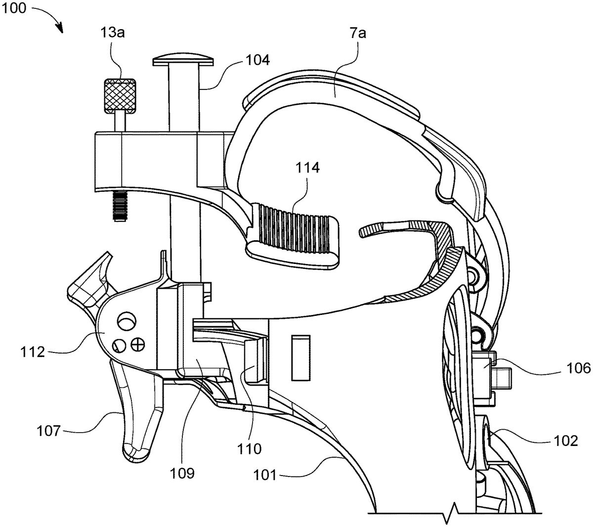
DETAILED DESCRIPTION OF THE INVENTION A description of variations of the invention will now be given with reference to the Figures. It is expected that the invention may be embodied in other specific forms without departing from its spirit or essential characteristics. The described variations are to be considered in all respects only as illustrative and not restrictive. Referring toFIG. 1, a clicker toggle mechanism100customizable and fastened to a housing unit is disclosed. In one variation, the clicker toggle mechanism100is securely affixed to adjustable levers (5aand7a) of the housing base unit101on both sides of a game controller or joystick via attaching members112(shown inFIG. 2). In one variation, the housing unit101is securely mounted on a game controller or joystick along with the respective position of one or more detachable and customizable removeable levers (5aand7a) in reference to the buttons and triggers of the game controller. In one variation, the clicker toggle mechanism100is configured to make the buttons and triggers of the game controller more accessible for a user with the use of detachable levers (5aand7a). In one variation, the clicker toggle mechanism100is further configured to prevent accidental activation of the levers or arms (5aand7a) by the user while playing or resting the device on a flat surface. A rocker mechanism or toggle106that allows access to the top buttons. A toggle mechanism103that allows the side of the hand to activate a button. A paddle102that is activated using the palm of your hand to activate a button on the gaming controller. Referring toFIG. 2, the clicker toggle mechanism100further configured to prevent excessive motion of the user's fingers and keeping thumbs on joysticks while using the game controller. In one variation, the clicker toggle mechanism100comprises a hole or oval shaped opening the armatures and toggle mechanisms to allow visibility of the button being used102. ...
DETAILED DESCRIPTION OF THE INVENTION
A description of variations of the invention will now be given with reference to the Figures. It is expected that the invention may be embodied in other specific forms without departing from its spirit or essential characteristics. The described variations are to be considered in all respects only as illustrative and not restrictive.
Referring toFIG. 1, a clicker toggle mechanism100customizable and fastened to a housing unit is disclosed. In one variation, the clicker toggle mechanism100is securely affixed to adjustable levers (5aand7a) of the housing base unit101on both sides of a game controller or joystick via attaching members112(shown inFIG. 2). In one variation, the housing unit101is securely mounted on a game controller or joystick along with the respective position of one or more detachable and customizable removeable levers (5aand7a) in reference to the buttons and triggers of the game controller. In one variation, the clicker toggle mechanism100is configured to make the buttons and triggers of the game controller more accessible for a user with the use of detachable levers (5aand7a). In one variation, the clicker toggle mechanism100is further configured to prevent accidental activation of the levers or arms (5aand7a) by the user while playing or resting the device on a flat surface. A rocker mechanism or toggle106that allows access to the top buttons. A toggle mechanism103that allows the side of the hand to activate a button. A paddle102that is activated using the palm of your hand to activate a button on the gaming controller.
Referring toFIG. 2, the clicker toggle mechanism100further configured to prevent excessive motion of the user's fingers and keeping thumbs on joysticks while using the game controller. In one variation, the clicker toggle mechanism100comprises a hole or oval shaped opening the armatures and toggle mechanisms to allow visibility of the button being used102. The lever arm114is securely affixed to the lever arm7aof the housing unit101of the game controller. In one variation, an adjustable screw member13ais movable and threaded and affixed at a top portion of the armature member114. Another screw member13bfor lever5awith same configuration and works similar as screw member13afor lever7a, is shown inFIG. 2. Henceforth, the configuration and working mechanism explained for screw member13bis applicable for screw member13aand lever arm114and5a(FIG. 1). The screw member13bis configured to move outward and inward from the toggle member107. In one variation, the clicker toggle mechanism100further comprises a stopper barrel guide104threaded with a cap to prevent excessive motion with a snap lock system110to secure it to the top base part101. In one variation, the lever arm member114includes an arm guide hole which allows stopper barrel guide104to pass through it. The arm guides prevent the stopper barrel guide104from deflecting left to right or in the x axis so the levers or triggers (5a/114and7a/114) do not slip off buttons of the game controller. The stopper barrel guide104is removable and inserted into the lever arm member114from the bottom portion. Part114can be optionally removed as required by users. The adjustable screw member13ais affixed to a bottom portion of the base piece112and stopper barrel guide104is affixed and configured to move along an opening in114(shown inFIG. 7) of the lever arm member114. In one variation, the clicker toggle107further comprises a snap piece with holes for positioning and locking an on and off position with an internal spring and bearing interlock system. The base clicker holder and mechanism112is snapped onto and affixed to101. The based part112can be removed by depressing a snap lock110and removed and replaced with part109(Shown inFIG. 11) to remove the clicker system entirely. In one variation, the clicker toggle107includes snaps to securely lock101to the gaming device. The lever arm distance stopper barrel guide104is configured to stop the lever arm member114from moving out of the stopper barrel guide104. In one variation, the clicker toggle mechanism100further comprises a clicker toggle107, positioned in line with the stopper barrel guide104. The clicker toggle107is configured to enable the trigger distance stopper pin13ato move inward and outward inside the barrel104and contacting the surface of the clicker toggle107when in the on or closed position. Alternately, clicker toggle107can be positioned in an open position and is locked in place to allow free full motion of part114.
Referring toFIG. 3, the clicker toggle mechanism100is activated via the clicker toggle107is disclosed. In one variation, the user could activate the clicker toggle mechanism100to make the buttons and triggers of the game controller more accessible for the user with the use of customizable and replacement of the levers (5a/114,7a/114,102,103and106). In one variation, the user could adjust the pull distance by rotating the screw members13boutwards and inwards from the lever arm member114. When the user clicks or presses the clicker toggle107with fingers, it creates a rotational force on the clicker toggle107which locks the snap bearings and created an interference surface for the screw in member13bto limit the distance the adjustable levers (5a/114and7a/114) can move, wherein the clicker toggle107is released to create a rotational force on the clicker toggle107which unlocks and opens to allow the screw member13bnormal range of motion of the adjustable levers (5a/114and7a/114). The screw member pin13bprevents the lever arm base part114from moving out of the stopper barrel guide104. The user could easily access the buttons on the game controller using the clicker toggle mechanism100and allows maximum control over the operation of the video game. The clicker toggle mechanism100allows the user to respond quickly within less time and shortens the reaction in the game which leads to increased control in a myriad of gaming situations and makes it possible for differently abled gamers to customize their controller to their best advantage and ease of use.
Referring toFIG. 4,FIG. 6,FIG. 7, andFIG. 9, arrangement, and operation of the clicker toggle mechanism100on activation and deactivation of the clicker toggle107is disclosed. In one variation, the clicker toggle mechanism100further comprises a spring115, which is connected to a ball bearing116. On pressing the clicker toggle107, the spring115inside the base holder109member compresses and allows the clicker part107to rotate to a new position and lock in a hole116(as shown inFIGS. 6 and 7). The clicker toggle107connects the barrel stopper104and with the screw13bwhen the user pulls on part114. This mechanism restricts the lever5aand7arange of motion which is joined with lever arm base part114when a user applies an exertion of external force. This in turn fully extends the screw13B in and follows the guide direction of stopper barrel guide104and can be infinitely adjusted to allow zero pull distance to free normal motion when clicker toggle107is moved to the second open position. To adjust the pull distance, the screw member13bis rotated outwards or inwards by the user.
ReferringFIG. 5andFIG. 11, illustrates when part112,107,114,104,13aand13bare removed. Releasing snap110and replacing with a basic locking bracket to secure the clicker toggle mechanism100and lever arms to the gaming device. This allows users full control on whether they wish to configure the trigger stroke controls, as shown inFIG. 2,FIG. 3,FIG. 4,FIG. 6,FIG. 7,FIG. 8,FIG. 9, andFIG. 10, or not to utilize them.
ReferringFIG. 6, In one variation, the adjustable screw13bis adjusted to a specific distance for limiting the pull distance. In one variation, the screw adjustment point is adjustable using trigger pull adjustment screw13b. When the adjustable screw13bhits the clicker toggle107, it stops the clicker/trigger from being fully pulled in one direction. The trigger pad114provided at the distal end of the arm5a, touches the stopper barrel guide104and retains its position relative to the clicker toggle107. This current view inFIG. 6shows the clicker toggle107in the open or full stroke unrestricted position. Pushing downward on clicker107move it to the movement limit by adding a barrier for the screw limit device13bto come in contact with directly. During unlocking, the flat surface of the clicker toggle107is again pressed, which compresses the spring retained inside its body, thereby enabling the lever arm114and5ato be restricted in its motion. The movement of114inside the barrel guide104and arm guide lever114allows for infinite stroke control during gameplay. In one variation, the user has the option to click the clicker toggle107is turned on or off during gameplay to provide full stroke or limited stroke as required.
In one variation, the stopper barrel guide104is configured to prevent the arm/taper-shaped member114from leaving the stopper barrel guide104. In one variation, the arm114fits tightly in the x-axis, which prevents slipping off of arms114from the triggers or buttons on the device. In another variation, the shape of the arm114allows for radial motion without any binding. In another variation, the arm114hits stopper pin13band the flat surface of clicker toggle107the pull distance of arm114and5aare limited.
Referring toFIG. 6, on releasing the clicker toggle107, a space is created between the screw member13band the clicker107, which is connected to the adjustable lever114and5athat could be pulled to activate the trigger or button. Flicking the part114and5aforward depresses the button on the top of the device without removing thumbs from the joysticks. In one variation, the force created by the spring115(shown inFIG. 4) is a smooth motion with a click sound on and off.
Referring toFIG. 7, a stopper barrel guide104is configured to prevent the exit of arm5afrom the lever am member114. In one variation, a loop of material/guide is provided to prevent the arm5afrom misalignment of13band107as it pushed forward and/or backward. In one variation, a tapered cut in lever arm member114is provided in the arms5aand7awhich allows the arms to be easily inserted within the clicker toggle mechanism100. The arms5a,7aand114could be replaced by the user. In one variation, the stopper barrel guide104is affixed to a bottom portion of the brace112and configured to move along the opening in114. The stopper barrel guide104is made of material including, but not limited to; steel, plastic or any suitable material for smooth operation.FIG. 8shows a detailed view of the clicker toggle mechanism100, according to a variation of the invention.
The advantages of the invention include: the clicker toggle mechanism100is configured to prevent excessive motion of the user's fingers. This reduces reaction time during gameplay movements and character control. The clicker toggle mechanism100is minutely adjusted to fine tune the required pull distance to activate the game function on the screen during gameplay. The clicker toggle mechanism100allows incremental control of the triggers suited to the custom needs of the user while playing with game controllers.
Preferred variations of this invention are described herein, including the best mode known to the inventors for carrying out the invention. It should be understood that the illustrated variations are exemplary only and should not be taken as limiting the scope of the invention.
The foregoing description comprise illustrative variations of the invention. Having thus described exemplary variations of the invention, it should be noted by those skilled in the art that the within disclosures are exemplary only, and that various other alternatives, adaptations, and modifications may be made within the scope of the invention. Merely listing or numbering the steps of a method in a certain order does not constitute any limitation on the order of the steps of that method. Many modifications and other variations of the invention will come to mind to one skilled in the art to which this invention pertains having the benefit of the teachings in the foregoing descriptions. Although specific terms may be employed herein, they are used only in generic and descriptive sense and not for purposes of limitation. Accordingly, the invention is not limited to the specific variations illustrated herein.
Claims
- A clicker mechanism for a video game controller, comprising: one or more levers, each lever configured to actuate at least one button of the video game controller;an armature member forming an end of each lever, the armature member being positioned to engage with a trigger of the video game controller when the armature member is pulled;a screw member disposed on the armature member;a clicker base having a clicker toggle, the clicker toggle having at least a first position and a second position;and a barrel guide adjacent to the clicker toggle;wherein in the first position, the clicker toggle is aligned to engage with the screw member to restrict a pull distance of the armature member when pulled, and wherein in the second position, the clicker toggle is aligned to not interfere with the screw member when the armature member is pulled.
- The clicker mechanism of claim 1, wherein the barrel guide extends through and slidably engages with a guide hole in the armature member.
- The clicker mechanism of claim 2, wherein the barrel guide restricts a motion of the armature member in an x-axis defined by a horizontal face of the video game controller.
- The clicker mechanism of claim 1, further comprising a spring and bearing system coupled to the clicker toggle.
- The clicker mechanism of claim 4, wherein the spring and bearing system engages with one or more holes in the clicker base to secure the clicker toggle in one or more positions.
- The clicker mechanism of claim 1, wherein the screw member is threadably inserted into the armature member.
- The clicker mechanism of claim 1, wherein the armature member is adjustable between zero pull distance to free normal motion by the screw member, wherein free normal motion is limited by a full trigger stroke of the video game controller.
- The clicker mechanism of claim 7, wherein the screw member is configured to prevent excessive motion of a user's fingers while using the game controller by limiting the pull distance.
- The clicker mechanism of claim 1, wherein the clicker base is removable.
- A system comprising: a housing unit configured for attachment to a video game controller;one or more clicker mechanisms according to claim 1 disposed on the housing unit;one or more paddles disposed on the housing unit each configured to actuate one or more buttons of the video game controller.
- The system of claim 10 further comprising a rocker to actuate two buttons of the video game controller alternately.
- The system of claim 10 wherein the clicker base removably attaches to the housing unit with one or more snap locks.
Disclaimer: Data collected from the USPTO and may be malformed, incomplete, and/or otherwise inaccurate.