U.S. Pat. No. 11,380,038
ANIMATION PRODUCTION SYSTEM FOR OBJECTS IN A VIRTUAL SPACE
AssigneeAniCast RM Inc.
Issue DateAugust 31, 2020
Illustrative Figure
Abstract
To enable you to take animations in a virtual space, an animation production method comprising: placing a first and second objects and a virtual camera in a virtual space; controlling an action of the first object in response to an operation from the first user; controlling an action of the second object in response to an operation from the second user; and controlling the camera in response to an operation from the first or second user or the second user to shoot the first and second objects.
Description
DESCRIPTION OF EMBODIMENTS The contents of embodiments of the present invention will be described with reference. An animation production method according to an embodiment of the present invention has the following configuration. [Item 1] An animation production method comprising: placing a first and second objects and a virtual camera in a virtual space; controlling an action of the first object in response to an operation from the first user; controlling an action of the second object in response to an operation from the second user; and controlling the camera in response to an operation from the first or second user or the second user to shoot the first and second objects. [Item 2] The animation production method according to item 1, the method further comprising: recording the action of the first object in a first track; and controlling the action of the second object while playing back the action of the first object recorded on the first track. [Item 3] The animation production method according to item 1, wherein: the second object is the same object as the first object, the method further comprising: recording the action of the first object in a first track; and changing the action of the first object in response to the operation of the second user while playing back the action of the first object recorded in the first track. A specific example of an animation production system according to an embodiment of the present invention will be described below with reference to the drawings. It should be noted that the present invention is not limited to these examples, and is intended to include all modifications within the meaning and scope of equivalence with the appended claims, as indicated by the appended claims. In the following description, the same elements are denoted by the ...
DESCRIPTION OF EMBODIMENTS
The contents of embodiments of the present invention will be described with reference. An animation production method according to an embodiment of the present invention has the following configuration.
[Item 1]
An animation production method comprising:
placing a first and second objects and a virtual camera in a virtual space;
controlling an action of the first object in response to an operation from the first user;
controlling an action of the second object in response to an operation from the second user; and
controlling the camera in response to an operation from the first or second user or the second user to shoot the first and second objects.
[Item 2]
The animation production method according to item 1, the method further comprising:
recording the action of the first object in a first track; and
controlling the action of the second object while playing back the action of the first object recorded on the first track.
[Item 3]
The animation production method according to item 1, wherein:
the second object is the same object as the first object, the method further comprising:
recording the action of the first object in a first track; and
changing the action of the first object in response to the operation of the second user while playing back the action of the first object recorded in the first track.
A specific example of an animation production system according to an embodiment of the present invention will be described below with reference to the drawings. It should be noted that the present invention is not limited to these examples, and is intended to include all modifications within the meaning and scope of equivalence with the appended claims, as indicated by the appended claims. In the following description, the same elements are denoted by the same reference numerals in the description of the drawings and overlapping descriptions are omitted.
Overview
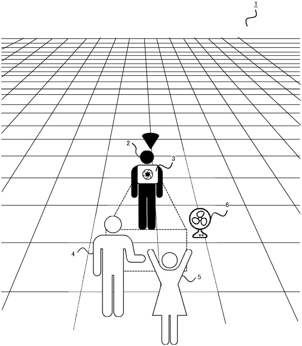
FIG. 1is a diagram illustrating an example of a virtual space displayed on a head mount display (HMD) mounted by a user in an animation production system of the present embodiment. In the animation production system of the present embodiment, a character4and a camera3are disposed in the virtual space1, and a character4is shot using the camera3. In the virtual space1, the photographer2is disposed, and the camera3is virtually operated by the photographer2. In the animation production system of the present embodiment, as shown inFIG. 1, a user makes an animation by placing a character4and a camera3while viewing the virtual space1from a bird's perspective with a TPV (Third Person's View), taking a character4with an FPV (First Person View; first person support) as a photographer2, and performing a character4with an FPV. In the virtual space1, a plurality of characters (in the example shown inFIG. 1, a character4and a character5) can be disposed, and the user can perform the performance while possessing a character4and a character5, respectively. That is, in the animation production system of the present embodiment, one can play a number of roles (roles). In addition, since the camera3can be virtually operated as the photographer2, natural camera work can be realized and the representation of the movie to be shot can be enriched. In addition, in the animation production system of the present embodiment, a plurality of users can collaborate to produce an animation. For example, one user may operate the character4to perform the performance, and another user may operate the camera man2to photograph the performance of the character4by the camera3. In addition, the lighting engineer performing lighting and the mixer performing voice mixing can be performed by the third and fourth users to share the work required for one animation. In addition, the animation production system of the present embodiment can perform these tasks asynchronously. That is, after the first user operates the character4and performs the performance, the second user operates the camera man2to take a photograph with one or more cuts while changing the angle of the camera3, and then the lighting engineer performs the lighting while adjusting the color, position, and timing of the lighting, so that the photographing operation can be performed asynchronously.
General Configuration
FIG. 2is a diagram illustrating an example of the overall configuration of an animation production system300according to an embodiment of the present invention. The animation production system300may comprise a plurality of character manipulation systems360and an image generator310serving as a host computer. The character manipulation system360may also include, for example, an HMD110, a controller210, and a control device350for controlling them. An infrared camera (not shown) for detecting the position, orientation and slope of the HMD110or the controller210can also be added to the character manipulation system360. These devices may be connected to each other by wired or wireless means. For example, each device may be equipped with a USB port to establish communication by cable connection, or communication may be established by wired or wireless, such as HDMI, wired LAN, infrared, Bluetooth™, WiFi™. The control device350may be a PC, a game machine, a portable communication terminal, or any other device having a calculation processing function. The control device350is communicatively connected to the image generating device310and can transmit input information from the user by the HMD110or the controller210to the image generating device310.
HMD110
FIG. 3shows a schematic view of the appearance of a head mount display (hereinafter referred to as HMD)110according to the present embodiment.FIG. 5shows a functional configuration diagram of the HMD110according to the present embodiment. The HMD110is mounted on the user's head and includes a display panel120for placement in front of the user's left and right eyes. Although an optically transmissive and non-transmissive display is contemplated as the display panel, this embodiment illustrates anon-transmissive display panel that can provide more immersion. The display panel120displays a left-eye image and a right-eye image, which can provide the user with a three-dimensional image by utilizing the visual difference of both eyes. If left- and right-eye images can be displayed, a left-eye display and a right-eye display can be provided separately, and an integrated display for left-eye and right-eye can be provided.
The housing portion130of the HMD110includes a sensor140. The sensor140may comprise, for example, a magnetic sensor, an acceleration sensor, or a gyro sensor, or a combination thereof, to detect actions such as the orientation or tilt of the user's head. When the vertical direction of the user's head is Y-axis, the axis corresponding to the user's anteroposterior direction is Z-axis, which connects the center of the display panel120with the user, and the axis corresponding to the user's left and right direction is X-axis, the sensor140can detect the rotation angle around the X-axis (so-called pitch angle), rotation angle around the Y-axis (so-called yaw angle), and rotation angle around the Z-axis (so-called roll angle).
In place of or in addition to the sensor140, the housing portion130of the HMD110may also include a plurality of light sources150(e.g., infrared light LEDs, visible light LEDs). A camera (e.g., an infrared light camera, a visible light camera) installed outside the HMD110(e.g., indoor, etc.) can detect the position, orientation, and tilt of the HMD110in a particular space by detecting these light sources. Alternatively, for the same purpose, the HMD110may be provided with a camera for detecting a light source installed in the housing portion130of the HMD110.
The housing portion130of the HMD110may also include an eye tracking sensor. The eye tracking sensor is used to detect the user's left and right eye gaze directions and gaze. There are various types of eye tracking sensors. For example, the position of reflected light on the cornea, which can be irradiated with infrared light that is weak in the left eye and right eye, is used as a reference point, the position of the pupil relative to the position of reflected light is used to detect the direction of the eye line, and the intersection point in the direction of the eye line in the left eye and right eye is used as a focus point.
Controller210
FIG. 4shows a schematic view of the appearance of the controller210according to the present embodiment.FIG. 6shows a functional configuration diagram of the controller210according to the present embodiment. The controller210can support the user to make predetermined inputs in the virtual space. The controller210may be configured as a set of left-hand220and right-hand230controllers. The left hand controller220and the right hand controller230may each have an operational trigger button240, an infrared LED250, a sensor260, a joystick270, and a menu button280.
The operation trigger button240is positioned as240a,240bin a position that is intended to perform an operation to pull the trigger with the middle finger and index finger when gripping the grip235of the controller210. The frame245formed in a ring-like fashion downward from both sides of the controller210is provided with a plurality of infrared LEDs250, and a camera (not shown) provided outside the controller can detect the position, orientation and slope of the controller210in a particular space by detecting the position of these infrared LEDs.
The controller210may also incorporate a sensor260to detect operations such as the orientation or tilt of the controller210. As sensor260, it may comprise, for example, a magnetic sensor, an acceleration sensor, or a gyro sensor, or a combination thereof. Additionally, the top surface of the controller210may include a joystick270and a menu button280. It is envisioned that the joystick270may be moved in a 360 degree direction centered on the reference point and operated with a thumb when gripping the grip235of the controller210. Menu buttons280are also assumed to be operated with the thumb. In addition, the controller210may include a vibrator (not shown) for providing vibration to the hand of the user operating the controller210. The controller210includes an input/output unit and a communication unit for outputting information such as the position, orientation, and slope of the controller210via a button or a joystick, and for receiving information from the host computer.
With or without the user grasping the controller210and manipulating the various buttons and joysticks, and with information detected by the infrared LEDs and sensors, the system can determine the user's hand operation and attitude, pseudo-displaying and operating the user's hand in the virtual space.
Control Device350
FIG. 7shows a functional configuration diagram of a control device350according to the present embodiment. The control device350may use a device such as a PC, a game machine, or a portable communication terminal, which has a function for storing information about the user's head operation or operation of the controller acquired by the user input information or the sensor, which is transmitted from the HMD110or the controller210, performing a predetermined computational processing, and generating an image. The control device350may include, for example, an input/output unit351for establishing a wired connection with a peripheral device such as an HMD110or controller210, and a communication unit352for establishing a wireless connection such as infrared, Bluetooth, or WiFi. Information received from the HMD110and/or the controller210through the I/O unit351and/or the communication unit352regarding the operation of the user's head or the operation or operation of the controller is detected in the control unit353as input content including the operation of the user's position, line of vision, posture, etc., speech, pronunciation, operation, etc. The control unit353may be composed of a CPU. However, by further providing a GPU specialized for image processing, information processing and image processing can be distributed and overall processing efficiency can be improved. The control unit353includes a user input detecting unit354which detects information (input information) received from the HMD110and/or the controller210regarding the operation of the user's head, the speech and pronunciation of the user, and the operation and operation of the controller. The input information is solved by the communication unit330and transmitted to the image producing device310. The communication unit330also receives information for reproducing the virtual space1from the image producing device310(which may be rendered video data or model information of an object disposed in a virtual space) and can display the virtual space1on the HMD110by the virtual space display unit355based on this information.
Image Generator310
FIG. 8shows a functional configuration diagram of an image producing device310according to this embodiment. The image generating device310may be a general purpose computer, such as a workstation or personal computer, or may be logically implemented by cloud computing. The image producing device310may include an input/output unit320for establishing a connection between the HMD110and the controller210, for example, when the image producing device310includes a peripheral device such as an HMD110or a controller210, and a communication unit330for establishing a connection by wires such as infrared, Bluetooth, WiFi, or a registered trademark, or a public telephone line. Information (input information) relating to the operation of the user's head or the operation or operation of the controller (input information) input from the HMD110and/or the controller210in the character manipulation system360is transmitted to the control unit340, and is detected in the control unit340as input content including the operation of the user's position, line of vision, attitude, etc., speech, pronunciation, operation, etc., and a control program stored in the storage unit350is executed in accordance with the user's input content to perform a process such as controlling the character and generating an image. The control unit340may be composed of a CPU. However, by further providing a GPU specialized for image processing, information processing and image processing can be distributed and overall processing efficiency can be improved. The image generating device310may also communicate with other computing processing devices to allow other computing processing devices to share information processing and image processing.
The control unit340includes a user input receiving unit410for acquiring input information from a user, a character control unit420for executing a control program stored in the control program storage unit520for a character stored in the character data storage unit510of the storage unit350, and an image producing unit430for generating an image based on a character control. Here, the control of the operation of a character can be realized by converting input information, such as the direction or tilt of the user head detected through the HMD110or the controller210, or the manual operation, into the operation of each portion of the bone structure created in accordance with the movement or restriction of the joints of the human body, and applying the operation of the bone structure to the previously stored character data by relating the bone structure. The character control unit420can operate various objects in the virtual space1, such as a character4or a camera3, according to operation by a plurality of users received from the plurality of character manipulation systems350. For example, the operation of the character4can be controlled based on the input information received from the first user from the first character manipulation system360, and the camera2can be operated based on the input information received from the second user from the second character manipulation system360to control the camera3. This allows a division of labor in which the first user performs the performance of the character4and the second user photographs it. Further, the control unit340includes a recording and playback executing unit440for recording and playing back an image-generated character on a track, and an editing executing unit450for editing each track and generating the final content.
The storage unit350includes a character data storage unit510for storing not only image data of a character but also information related to a character such as attributes of a character. The control program storage unit520stores a program for controlling the operation of a character or an expression in the virtual space. The storage unit350includes a track storage unit530for storing action data composed of parameters for controlling the movement of a character in a dynamic image generated by the image producing unit430.
FIG. 9is a flowchart illustrating an example of a track generation process according to an embodiment of the present invention.
First, the recording and reproduction executing unit440of the control unit340of the image producing device310starts recording for storing action data of the moving image related to operation by the first character in the virtual space in the first track of the track storage unit530(S101). Here, the position of the camera where the character is to be shot and the viewpoint of the camera (e.g., FPV, TPV, etc.) can be set. For example, in the virtual space1illustrated inFIG. 1, the position where the cameraman2is disposed and the angle of the camera3can be set with respect to the character4corresponding to the first character. The recording start operation may be indicated by a remote controller, such as controller210, or may be indicated by other terminals. The operation may also be performed by a user who is equipped with an HMD110to manipulate the controller210, to play a character, or by a user other than the user who performs the character. In addition, the recording process may be automatically started based on detecting an operation by a user who performs the character described below.
Subsequently, the user input detecting unit410of the control unit340detects information received from the HMD110and/or the controller210relating to the operation of the user's head, speech or pronunciation of the user, and operation or operation of the controller (S102). For example, when the user mounting the HMD110tilts the head, the sensor140provided in the HMD110detects the tilt and transmits information about the tilt to the image generating device310. The image generating device310receives information about the operation of the user through the communication unit330, and the user input detecting unit410detects the operation of the user's head based on the received information. Also, when a user performs a predetermined operation or operation, such as lifting the controller210or pressing a button, the sensor260provided in the controller detects the operation and/or operation and transmits information about the operation and/or operation to the image generating device310using the controller210. The image producing device310receives information related to the user's controller operation and operation through the communication unit330, and the user input detecting unit410detects the user's controller operation and operation based on the received information.
Subsequently, the character control unit420of the control unit340controls the operation of the first character in the virtual space based on the operation of the detected user (S103). For example, based on the user detecting an operation to tilt the head, the character control unit420controls to tilt the head of the first character. Also, based on the fact that the user lifts the controller and detects pressing a predetermined button on the controller, the character control unit420controls something while extending the arm of the first character upward. In this manner, the character control unit420controls the first character to perform the corresponding operation each time the user input detecting unit410detects an operation by a user transmitted from the HMD110or the controller210. Stores parameters related to the operation and/or operation detected by the user input detecting unit410in the first track of the track storage unit530. Alternatively, the character may be controlled to perform a predetermined performance action without user input, the action data relating to the predetermined performance action may be stored in the first track, or both user action and action data relating to the predetermined behavior may be stored.
Subsequently, the recording and reproduction executing unit440confirms whether or not the user receives the instruction to end the recording (S104), and when receiving the instruction to end the recording, completes the recording of the first track related to the first character (S105). The recording and reproduction executing unit440continues the recording process unless the user receives an instruction to end the recording. Here, the recording and reproduction executing unit440may perform the process of automatically completing the recording when the operation by the user acting as a character is no longer detected. It is also possible to execute the recording termination process at a predetermined time by activating a timer rather than accepting instructions from the user.
Subsequently, the recording and playback executing unit440starts recording for storing action data of the moving image associated with operation by the second character in the virtual space in the second track of the track storage unit530(S106). Here, the position of the camera where the character is to be shot and the viewpoint of the camera (e.g., FPV, TPV, etc.) can be set. For example, in the virtual space1illustrated inFIG. 1, the position where the cameraman2is disposed and the angle of the camera3can be set with respect to the character5corresponding to the second character. For example, the user may set the camera viewpoint by the FPV of the character5, perform the playback processing of the first track, and perform the desired operation by the user who performs the character5while checking the operation of the character4. The recording start operation may be indicated by a remote controller, such as controller210, or may be indicated by other terminals. The operation may also be performed by a user who is equipped with an HMD110to manipulate the controller210, to play a character, or by a user other than the user who performs the character. The recording process may also be automatically initiated based on the detection of an action and/or operation by the user performing the characters described below.
Subsequently, the user input detecting unit410of the control unit340detects information received from the HMD110and/or the controller210relating to the operation of the user's head, speech or pronunciation of the user, and operation or operation of the controller (S107). Here, the user may be the same user as the user performing the first character, or may be a different user. For example, when the user mounting the HMD110tilts the head, the sensor140provided in the HMD110detects the tilt and transmits information about the tilt to the image generating device310. The image generating device310receives information about the operation of the user through the communication unit330, and the user input detecting unit410detects the operation of the user's head based on the received information. Also, when a user performs a predetermined operation or operation, such as lifting the controller210, shaking the controller210left or right, or pressing a button, the sensor260provided in the controller detects the operation and/or operation and transmits information about the operation and/or operation to the image generating device310using the controller210. The image producing device310receives information related to the user's controller operation and operation through the communication unit330, and the user input detecting unit410detects the user's controller operation and operation based on the received information.
Subsequently, the character control unit420of the control unit340controls the operation of the second character in the virtual space based on the operation of the detected user (S108). For example, based on the user detecting an operation to tilt the head, the character control unit420controls to tilt the head of the second character. The character control unit420also controls the opening of the finger (i.e. “by”) by shaking the arm of the second character, based on the fact that the user has raised the controller to the right and left or pressed a predetermined button on the controller. In this manner, the character control unit420controls the second character to perform the corresponding operation each time the user input detecting unit410detects an operation by a user transmitted from the HMD110or the controller210. The parameters related to the operation and/or operation detected by the user input detecting unit410are stored in the second track of the track storage unit530. Alternatively, the character may be controlled to perform a predetermined performance action without user input, the action data relating to the predetermined performance action may be stored in a second track, or both user action and action data relating to a predetermined operation may be stored.
Subsequently, the recording and reproduction executing unit440confirms whether or not the user receives the instruction to end the recording (S109), and when the instruction to terminate the recording is received, the recording of the second track related to the second character is completed (S110). The recording and reproduction executing unit440continues the recording process unless the user receives an instruction to end the recording. Here, the recording and reproduction executing unit440may perform the process of automatically completing the recording when the operation by the user acting as a character is no longer detected.
FIG. 10is a flowchart illustrating an example of a track editing process according to an embodiment of the present invention.
First, the editing execution unit450of the control unit340of the image generating device310performs a process of editing the first track stored in the track storage unit530(S201). For example, the user edits a first track (T1) associated with the first character via a user interface for track editing, as shown inFIG. 11(a). For example, the user interface displays the area in which the first track is stored along a time series. The user selects a desired bar so that the 3D model of the character is rendered based on the parameters and character data of the stored moving image, and the moving image of the character (e.g., the character4) disposed in the virtual space as shown inFIG. 1is reproduced. It should be noted that as a user interface for editing tracks, it is also possible to display, for example, a track name and title (e.g., a “first character”) in a list format, in addition to the display described above. Alternatively, the user interface may allow editing to be performed while the moving image of the character is played directly, or a keyframe of the moving image may be displayed in which the user selects the keyframe to be edited, without showing the tracks or lists as shown inFIG. 11. In addition, among the 3D characters displayed as a dynamic image, it is possible to perform a process such as changing the color of the character selected as an editing target by the selected time.
As an editing process, for example, inFIG. 1, it is contemplated that the placement position of the character4corresponding to the first character is changed in the virtual space1, the shooting position and angle of the character4is changed, and the shooting viewpoint (FPV, TPV) is changed. It is also possible to change or delete the time scale.
Alternatively, a portion of the operation of the character4may be changed as an editing process. For example, for a first character played back in a track (T1), a user may specify a part of the body to be edited and only operate the specified part by operation using the controller210or the HMD110. For example, a user may specify an arm of a first character to manipulate only the arm of the first character by the operation of controller210while playing back the operation of the first character to modify the movement of the arm.
Next, the editing execution unit450performs the process of editing the second track stored in the track storage unit530(S202). For example, the user selects the option (not shown) to edit a second track (T2) associated with the second character via a user interface for track editing, and places a bar, via a user interface, as shown inFIG. 11b, indicating the area in which the second track is stored along a time series. As shown inFIG. 11(b), the user can adjust the second track relatively, such as synchronizing the playback timing of each track while editing the second track independently of the first track. Similarly, the user may edit other tracks (e.g., a third track (T3)).
As an editing process, for example, inFIG. 1, it is contemplated that the placement position of the character5corresponding to the second character is changed in the virtual space1, the shooting position and angle of the character5is changed, and the shooting viewpoint (FPV, TPV) is changed. It is also possible to change or delete the time scale. Here, as an editing process, the user may change the placement position of the second character5in the virtual space1opposite the character4corresponding to the first character.
Further, by playing back each track as an editing process, an animated moving image that is realized in a virtual space as a whole can be created by playing an active image including the operation of a character corresponding to each track in a virtual space. In addition, by playing back each track, it is possible to edit animated moving images that can even be realized in a virtual space by not only reproducing the movement of the character, but also changing the set of the background of the character, increasing or decreasing the object head containing the character, changing the setting of writing, changing the clothing of the character or attaching an accessory, changing the wind amount or direction of the character, and changing the character as is the action data.
After the editing process is completed, the editing execution unit450stores the edited contents in response to a user's request or automatically (S203).
The editing process of S201and S202can be performed in any order, and can be moved back and forth. The storage processing of S203can also be performed each time the editing of S201and S202is performed. Editing can also be terminated by editing S201only.
In addition, the track generation process described above can be executed independently for each user. Accordingly, after a track generation process is performed by the first user, a track generation process can be performed by the second user. Accordingly, for example, after the first user operates the character4and stores the performance in the first track storage section530as a track in which the first user operates, the second user can control the camera3by operating the camera2while playing the first track, take a later picture of the performance of the character4, and store the operation of the camera3(or the operation of the camera man2) in the second track. This allows the first and second tracks to be executed to create an image captured by the second user of the character4performed by the first user.
The track editing process described above can also be performed independently for each user. Accordingly, after the track creation process is performed by the first user, the editing process of the track created by the first user by the second user can be performed. Accordingly, the operation of one object can be defined by the operation in which the first user and the second user bring together their favorite parts. For example, after the first user operates the character4to record the wrap operation on the track, the second user may manipulate the character4to add a dance operation that is performed between the wraps. In this way, even if the same character4is used, when performing a different movement, a user who is skilled in the art is able to perform the operation according to the movement, thereby enabling the overall performance of the high-quality movement.
As described above, by applying the method of multitrack recording (MTR) to the animation production according to the present embodiment, the character operation linked to the user operation can be stored in each track, and the animation production can be realized easily and efficiently by performing editing work within each track or between each track.
Although the present embodiment has been described above, the above-described embodiment is intended to facilitate the understanding of the present invention and is not intended to be a limiting interpretation of the present invention. The present invention may be modified and improved without departing from the spirit thereof, and the present invention also includes its equivalent.
For example, in this embodiment, while a character has been described as an example with respect to a track generation method and an editing method, the method disclosed in this embodiment may be applied to an object (vehicle, structure, article, etc.) comprising an action, including not only a character, but also a character.
For example, although the image producing device310has been described in this embodiment as separate from the HMD110, the HMD110may include all or part of the configuration and functions provided by the image producing device310.
Explanation of Symbols
1virtual space
2cameraman
3cameras
4characters
5characters
110HMD
210controller
310Image Generator
Claims
- An animation production method comprising: placing a first and second objects and a virtual camera in a virtual space;controlling an action of the first object in response to an operation from a first user;controlling an action of the second object in response to an operation from a second user;and controlling the camera in response to an operation from the first or second user to shoot the first and second objects.
- The animation production method according to claim 1 , the method further comprising: recording the action of the first object in a first track;and controlling the action of the second object while playing back the action of the first object recorded on the first track.
- The animation production method according to claim 1 , wherein: the second object is the same object as the first object, the method further comprising: recording the action of the first object in a first track;and changing the action of the first object in response to the operation of the second user while playing back the action of the first object recorded in the first track.
Disclaimer: Data collected from the USPTO and may be malformed, incomplete, and/or otherwise inaccurate.