U.S. Pat. No. 11,331,570
GAME SYSTEM, STORAGE MEDIUM HAVING STORED THEREIN GAME PROGRAM, INFORMATION PROCESSING APPARATUS, AND GAME PROCESSING METHOD
AssigneeNintendo Co., Ltd.
Issue DateSeptember 17, 2020
Illustrative Figure
Abstract
An example of an operation device includes an inertial sensor and a vibrator, transmits inertia data based on an output of the inertial sensor to an information processing apparatus, and vibrates the vibrator based on a vibration control signal received from the information processing apparatus. One or more processors of the information processing apparatus execute game processing, and in a predetermined situation in the game processing, cause the vibration control signal for vibrating the vibrator to be output from the information processing apparatus. The one or more processors, based on the inertia data from the operation device, determine whether or not the operation device is moving, and at least under the condition that it is determined that the operation device is not moving, limit the vibration so that the vibrator of the operation device is not vibrated or the vibration is weakened in the predetermined situation.
Description
DETAILED DESCRIPTION OF NON-LIMITING EXAMPLE EMBODIMENTS [1. Configuration of Game System] A game system according to an example of an exemplary embodiment is described below. An example of a game system1according to the exemplary embodiment includes a main body apparatus (an information processing apparatus; which functions as a game apparatus main body in the exemplary embodiment)2, a left controller3, and a right controller4. Each of the left controller3and the right controller4is attachable to and detachable from the main body apparatus2. That is, the game system1can be used as a unified apparatus obtained by attaching each of the left controller3and the right controller4to the main body apparatus2. Further, in the game system1, the main body apparatus2, the left controller3, and the right controller4can also be used as separate bodies (seeFIG. 2). Hereinafter, first, the hardware configuration of the game system1according to the exemplary embodiment is described, and then, the control of the game system1according to the exemplary embodiment is described. FIG. 1is a diagram showing an example of the state where the left controller3and the right controller4are attached to the main body apparatus2. As shown inFIG. 1, each of the left controller3and the right controller4is attached to and unified with the main body apparatus2. The main body apparatus2is an apparatus for performing various processes (e.g., game processing) in the game system1. The main body apparatus2includes a display12. Each of the left controller3and the right controller4is an apparatus including operation sections with which a user provides inputs. FIG. 2is a diagram showing an example of the state where each of the left controller3and the right controller4is detached from the main body apparatus2. As shown inFIGS. 1 and 2, the left controller3and the right controller4are attachable to and detachable from the main body apparatus2. It should be noted that hereinafter, the left controller3and ...
DETAILED DESCRIPTION OF NON-LIMITING EXAMPLE EMBODIMENTS
[1. Configuration of Game System]
A game system according to an example of an exemplary embodiment is described below. An example of a game system1according to the exemplary embodiment includes a main body apparatus (an information processing apparatus; which functions as a game apparatus main body in the exemplary embodiment)2, a left controller3, and a right controller4. Each of the left controller3and the right controller4is attachable to and detachable from the main body apparatus2. That is, the game system1can be used as a unified apparatus obtained by attaching each of the left controller3and the right controller4to the main body apparatus2. Further, in the game system1, the main body apparatus2, the left controller3, and the right controller4can also be used as separate bodies (seeFIG. 2). Hereinafter, first, the hardware configuration of the game system1according to the exemplary embodiment is described, and then, the control of the game system1according to the exemplary embodiment is described.
FIG. 1is a diagram showing an example of the state where the left controller3and the right controller4are attached to the main body apparatus2. As shown inFIG. 1, each of the left controller3and the right controller4is attached to and unified with the main body apparatus2. The main body apparatus2is an apparatus for performing various processes (e.g., game processing) in the game system1. The main body apparatus2includes a display12. Each of the left controller3and the right controller4is an apparatus including operation sections with which a user provides inputs.
FIG. 2is a diagram showing an example of the state where each of the left controller3and the right controller4is detached from the main body apparatus2. As shown inFIGS. 1 and 2, the left controller3and the right controller4are attachable to and detachable from the main body apparatus2. It should be noted that hereinafter, the left controller3and the right controller4will occasionally be referred to collectively as a “controller”.
FIG. 3is six orthogonal views showing an example of the main body apparatus2. As shown inFIG. 3, the main body apparatus2includes an approximately plate-shaped housing11. In the exemplary embodiment, a main surface (in other words, a surface on a front side, i.e., a surface on which the display12is provided) of the housing11has a generally rectangular shape.
It should be noted that the shape and the size of the housing11are optional. As an example, the housing11may be of a portable size. Further, the main body apparatus2alone or the unified apparatus obtained by attaching the left controller3and the right controller4to the main body apparatus2may function as a mobile apparatus. The main body apparatus2or the unified apparatus may function as a handheld apparatus or a portable apparatus.
As shown inFIG. 3, the main body apparatus2includes the display12, which is provided on the main surface of the housing11. The display12displays an image generated by the main body apparatus2. In the exemplary embodiment, the display12is a liquid crystal display device (LCD). The display12, however, may be a display device of any type.
Further, the main body apparatus2includes a touch panel13on a screen of the display12. In the exemplary embodiment, the touch panel13is of a type that allows a multi-touch input (e.g., a capacitive type). The touch panel13, however, may be of any type. For example, the touch panel13may be of a type that allows a single-touch input (e.g., a resistive type).
The main body apparatus2includes speakers (i.e., speakers88shown inFIG. 6) within the housing11. As shown inFIG. 3, speaker holes11aand11bare formed on the main surface of the housing11. Then, sounds output from the speakers88are output through the speaker holes11aand11b.
Further, the main body apparatus2includes a left terminal17, which is a terminal for the main body apparatus2to perform wired communication with the left controller3, and a right terminal21, which is a terminal for the main body apparatus2to perform wired communication with the right controller4.
As shown inFIG. 3, the main body apparatus2includes a slot23. The slot23is provided on an upper side surface of the housing11. The slot23is so shaped as to allow a predetermined type of storage medium to be attached to the slot23. The predetermined type of storage medium is, for example, a dedicated storage medium (e.g., a dedicated memory card) for the game system1and an information processing apparatus of the same type as the game system1. The predetermined type of storage medium is used to store, for example, data (e.g., saved data of an application or the like) used by the main body apparatus2and/or a program (e.g., a program for an application or the like) executed by the main body apparatus2. Further, the main body apparatus2includes a power button28.
The main body apparatus2includes a lower terminal27. The lower terminal27is a terminal for the main body apparatus2to communicate with a cradle. In the exemplary embodiment, the lower terminal27is a USB connector (more specifically, a female connector). Further, when the unified apparatus or the main body apparatus2alone is mounted on the cradle, the game system1can display on a stationary monitor an image generated by and output from the main body apparatus2. Further, in the exemplary embodiment, the cradle has the function of charging the unified apparatus or the main body apparatus2alone mounted on the cradle. Further, the cradle has the function of a hub device (specifically, a USB hub).
FIG. 4is six orthogonal views showing an example of the left controller3. As shown inFIG. 4, the left controller3includes a housing31. In the exemplary embodiment, the housing31has a vertically long shape, i.e., is shaped to be long in an up-down direction (i.e., a y-axis direction shown inFIGS. 1 and 4). In the state where the left controller3is detached from the main body apparatus2, the left controller3can also be held in the orientation in which the left controller3is vertically long. The housing31has such a shape and a size that when held in the orientation in which the housing31is vertically long, the housing31can be held with one hand, particularly the left hand. Further, the left controller3can also be held in the orientation in which the left controller3is horizontally long. When held in the orientation in which the left controller3is horizontally long, the left controller3may be held with both hands.
The left controller3includes an analog stick32. As shown inFIG. 4, the analog stick32is provided on a main surface of the housing31. The analog stick32can be used as a direction input section with which a direction can be input. The user tilts the analog stick32and thereby can input a direction corresponding to the direction of the tilt (and input a magnitude corresponding to the angle of the tilt). It should be noted that the left controller3may include a directional pad, a slide stick that allows a slide input, or the like as the direction input section, instead of the analog stick. Further, in the exemplary embodiment, it is possible to provide an input by pressing the analog stick32.
The left controller3includes various operation buttons. The left controller3includes four operation buttons33to36(specifically, a right direction button33, a down direction button34, an up direction button35, and a left direction button36) on the main surface of the housing31. Further, the left controller3includes a record button37and a “−” (minus) button47. The left controller3includes a first L-button38and a ZL-button39in an upper left portion of a side surface of the housing31. Further, the left controller3includes a second L-button43and a second R-button44, on the side surface of the housing31on which the left controller3is attached to the main body apparatus2. These operation buttons are used to give instructions depending on various programs (e.g., an OS program and an application program) executed by the main body apparatus2.
Further, the left controller3includes a terminal42for the left controller3to perform wired communication with the main body apparatus2.
FIG. 5is six orthogonal views showing an example of the right controller4. As shown inFIG. 5, the right controller4includes a housing51. In the exemplary embodiment, the housing51has a vertically long shape, i.e., is shaped to be long in the up-down direction. In the state where the right controller4is detached from the main body apparatus2, the right controller4can also be held in the orientation in which the right controller4is vertically long. The housing51has such a shape and a size that when held in the orientation in which the housing51is vertically long, the housing51can be held with one hand, particularly the right hand. Further, the right controller4can also be held in the orientation in which the right controller4is horizontally long. When held in the orientation in which the right controller4is horizontally long, the right controller4may be held with both hands.
Similarly to the left controller3, the right controller4includes an analog stick52as a direction input section. In the exemplary embodiment, the analog stick52has the same configuration as that of the analog stick32of the left controller3. Further, the right controller4may include a directional pad, a slide stick that allows a slide input, or the like, instead of the analog stick. Further, similarly to the left controller3, the right controller4includes four operation buttons53to56(specifically, an A-button53, a B-button54, an X-button55, and a Y-button56) on a main surface of the housing51. Further, the right controller4includes a “+” (plus) button57and a home button58. Further, the right controller4includes a first R-button60and a ZR-button61in an upper right portion of a side surface of the housing51. Further, similarly to the left controller3, the right controller4includes a second L-button65and a second R-button66.
Further, the right controller4includes a terminal64for the right controller4to perform wired communication with the main body apparatus2.
FIG. 6is a block diagram showing an example of the internal configuration of the main body apparatus2. The main body apparatus2includes components81to91,97, and98shown inFIG. 6in addition to the components shown inFIG. 3. Some of the components81to91,97, and98may be mounted as electronic components on an electronic circuit board and accommodated in the housing11.
The main body apparatus2includes a processor81. The processor81is an information processing section for executing various types of information processing to be executed by the main body apparatus2. For example, the processor81may be composed only of a CPU (Central Processing Unit), or may be composed of a SoC (System-on-a-chip) having a plurality of functions such as a CPU function and a GPU (Graphics Processing Unit) function. The processor81executes an information processing program (e.g., a game program) stored in a storage section (specifically, an internal storage medium such as a flash memory84, an external storage medium attached to the slot23, or the like), thereby performing the various types of information processing.
The main body apparatus2includes a flash memory84and a DRAM (Dynamic Random Access Memory)85as examples of internal storage media built into the main body apparatus2. The flash memory84and the DRAM85are connected to the processor81. The flash memory84is a memory mainly used to store various data (or programs) to be saved in the main body apparatus2. The DRAM85is a memory used to temporarily store various data used for information processing.
The main body apparatus2includes a slot interface (hereinafter abbreviated as “I/F”)91. The slot I/F91is connected to the processor81. The slot I/F91is connected to the slot23, and in accordance with an instruction from the processor81, reads and writes data from and to the predetermined type of storage medium (e.g., a dedicated memory card) attached to the slot23.
The processor81appropriately reads and writes data from and to the flash memory84, the DRAM85, and each of the above storage media, thereby performing the above information processing.
The main body apparatus2includes a network communication section82. The network communication section82is connected to the processor81. The network communication section82communicates (specifically, through wireless communication) with an external apparatus via a network. In the exemplary embodiment, as a first communication form, the network communication section82connects to a wireless LAN and communicates with an external apparatus, using a method compliant with the Wi-Fi standard. Further, as a second communication form, the network communication section82wirelessly communicates with another main body apparatus2of the same type, using a predetermined communication method (e.g., communication based on a unique protocol or infrared light communication). It should be noted that the wireless communication in the above second communication form achieves the function of enabling so-called “local communication” in which the main body apparatus2can wirelessly communicate with another main body apparatus2placed in a closed local network area, and the plurality of main body apparatuses2directly communicate with each other to transmit and receive data.
The main body apparatus2includes a controller communication section83. The controller communication section83is connected to the processor81. The controller communication section83wirelessly communicates with the left controller3and/or the right controller4. The communication method between the main body apparatus2and the left controller3and the right controller4is optional. In the exemplary embodiment, the controller communication section83performs communication compliant with the Bluetooth (registered trademark) standard with the left controller3and with the right controller4.
The processor81is connected to the left terminal17, the right terminal21, and the lower terminal27. When performing wired communication with the left controller3, the processor81transmits data to the left controller3via the left terminal17and also receives operation data from the left controller3via the left terminal17. Further, when performing wired communication with the right controller4, the processor81transmits data to the right controller4via the right terminal21and also receives operation data from the right controller4via the right terminal21. Further, when communicating with the cradle, the processor81transmits data to the cradle via the lower terminal27. As described above, in the exemplary embodiment, the main body apparatus2can perform both wired communication and wireless communication with each of the left controller3and the right controller4. Further, when the unified apparatus obtained by attaching the left controller3and the right controller4to the main body apparatus2or the main body apparatus2alone is attached to the cradle, the main body apparatus2can output data (e.g., image data or sound data) to the stationary monitor or the like via the cradle.
Here, the main body apparatus2can communicate with a plurality of left controllers3simultaneously (in other words, in parallel). Further, the main body apparatus2can communicate with a plurality of right controllers4simultaneously (in other words, in parallel). Thus, a plurality of users can simultaneously provide inputs to the main body apparatus2, each using a set of the left controller3and the right controller4. As an example, a first user can provide an input to the main body apparatus2using a first set of the left controller3and the right controller4, and simultaneously, a second user can provide an input to the main body apparatus2using a second set of the left controller3and the right controller4.
Further, the display12is connected to the processor81. The processor81displays a generated image (e.g., an image generated by executing the above information processing) and/or an externally acquired image on the display12.
The main body apparatus2includes a codec circuit87and speakers (specifically, a left speaker and a right speaker)88. The codec circuit87is connected to the speakers88and a sound input/output terminal25and also connected to the processor81. The codec circuit87is a circuit for controlling the input and output of sound data to and from the speakers88and the sound input/output terminal25.
The main body apparatus2includes a power control section97and a battery98. The power control section97is connected to the battery98and the processor81. Further, although not shown inFIG. 6, the power control section97is connected to components of the main body apparatus2(specifically, components that receive power supplied from the battery98, the left terminal17, and the right terminal21). Based on a command from the processor81, the power control section97controls the supply of power from the battery98to the above components.
Further, the battery98is connected to the lower terminal27. When an external charging device (e.g., the cradle) is connected to the lower terminal27, and power is supplied to the main body apparatus2via the lower terminal27, the battery98is charged with the supplied power.
FIG. 7is a block diagram showing examples of the internal configurations of the main body apparatus2, the left controller3, and the right controller4. It should be noted that the details of the internal configuration of the main body apparatus2are shown inFIG. 6and therefore are omitted inFIG. 7.
The left controller3includes a communication control section101, which communicates with the main body apparatus2. As shown inFIG. 7, the communication control section101is connected to components including the terminal42. In the exemplary embodiment, the communication control section101can communicate with the main body apparatus2through both wired communication via the terminal42and wireless communication not via the terminal42. The communication control section101controls the method for communication performed by the left controller3with the main body apparatus2. That is, when the left controller3is attached to the main body apparatus2, the communication control section101communicates with the main body apparatus2via the terminal42. Further, when the left controller3is detached from the main body apparatus2, the communication control section101wirelessly communicates with the main body apparatus2(specifically, the controller communication section83). The wireless communication between the communication control section101and the controller communication section83is performed in accordance with the Bluetooth (registered trademark) standard, for example.
Further, the left controller3includes a memory102such as a flash memory. The communication control section101includes, for example, a microcomputer (or a microprocessor) and executes firmware stored in the memory102, thereby performing various processes.
The left controller3includes buttons103(specifically, the buttons33to39,43,44, and47). Further, the left controller3includes the analog stick (“stick” inFIG. 7)32. Each of the buttons103and the analog stick32outputs information regarding an operation performed on itself to the communication control section101repeatedly at appropriate timing.
The left controller3includes inertial sensors. Specifically, the left controller3includes an acceleration sensor104. Further, the left controller3includes an angular velocity sensor105. In the exemplary embodiment, the acceleration sensor104detects the magnitudes of accelerations along predetermined three axial (e.g., xyz axes shown inFIG. 4) directions. It should be noted that the acceleration sensor104may detect an acceleration along one axial direction or accelerations along two axial directions. In the exemplary embodiment, the angular velocity sensor105detects angular velocities about predetermined three axes (e.g., the xyz axes shown inFIG. 4). It should be noted that the angular velocity sensor105may detect an angular velocity about one axis or angular velocities about two axes. Each of the acceleration sensor104and the angular velocity sensor105is connected to the communication control section101. Then, the detection results of the acceleration sensor104and the angular velocity sensor105are output to the communication control section101repeatedly at appropriate timing.
The communication control section101acquires information regarding an input (specifically, information regarding an operation or the detection result of the sensor) from each of input sections (specifically, the buttons103, the analog stick32, and the sensors104and105). The communication control section101transmits operation data including the acquired information (or information obtained by performing predetermined processing on the acquired information) to the main body apparatus2. It should be noted that the operation data is transmitted repeatedly, once every predetermined time. It should be noted that the interval at which the information regarding an input is transmitted from each of the input sections to the main body apparatus2may or may not be the same.
The above operation data is transmitted to the main body apparatus2, whereby the main body apparatus2can obtain inputs provided to the left controller3. That is, the main body apparatus2can determine operations on the buttons103and the analog stick32based on the operation data. Further, the main body apparatus2can calculate information regarding the motion and/or the orientation of the left controller3based on the operation data (specifically, the detection results of the acceleration sensor104and the angular velocity sensor105).
The left controller3includes a vibrator107for giving notification to the user by a vibration. In the exemplary embodiment, the vibrator107is controlled by a vibration control signal from the main body apparatus2. That is, if receiving the above vibration control signal from the main body apparatus2, the communication control section101drives the vibrator107in accordance with the received vibration control signal. Here, the left controller3includes a codec section106. If receiving the above vibration control signal, the communication control section101outputs a control signal corresponding to the vibration control signal to the codec section106. The codec section106generates a driving signal for driving the vibrator107from the control signal from the communication control section101and outputs the driving signal to the vibrator107. Consequently, the vibrator107operates.
More specifically, the vibrator107is a linear vibration motor. Unlike a regular motor that rotationally moves, the linear vibration motor is driven in a predetermined direction in accordance with an input voltage and therefore can be vibrated at an amplitude and a frequency corresponding to the waveform of the input voltage. In the exemplary embodiment, a vibration control signal transmitted from the main body apparatus2to the left controller3may be a digital signal representing the frequency and the amplitude every unit of time. In another exemplary embodiment, the main body apparatus2may transmit information indicating the waveform itself. The transmission of only the amplitude and the frequency, however, enables a reduction in the amount of communication data. Additionally, to further reduce the amount of data, only the differences between the numerical values of the amplitude and the frequency at that time and the previous values may be transmitted, instead of the numerical values. In this case, the codec section106converts a digital signal indicating the values of the amplitude and the frequency acquired from the communication control section101into the waveform of an analog voltage and inputs a voltage in accordance with the resulting waveform, thereby driving the vibrator107. Thus, the main body apparatus2changes the amplitude and the frequency to be transmitted every unit of time and thereby can control the amplitude and the frequency at which the vibrator107is to be vibrated at that time. It should be noted that not only a single amplitude and a single frequency, but also two or more amplitudes and two or more frequencies may be transmitted from the main body apparatus2to the left controller3. In this case, the codec section106combines waveforms indicated by the plurality of received amplitudes and frequencies and thereby can generate the waveform of a voltage for controlling the vibrator107.
The left controller3includes a power supply section108. In the exemplary embodiment, the power supply section108includes a battery and a power control circuit. Although not shown inFIG. 7, the power control circuit is connected to the battery and also connected to components of the left controller3(specifically, components that receive power supplied from the battery).
As shown inFIG. 7, the right controller4includes a communication control section111, which communicates with the main body apparatus2. Further, the right controller4includes a memory112, which is connected to the communication control section111. The communication control section111is connected to components including the terminal64. The communication control section111and the memory112have functions similar to those of the communication control section101and the memory102, respectively, of the left controller3. Thus, the communication control section111can communicate with the main body apparatus2through both wired communication via the terminal64and wireless communication not via the terminal64(specifically, communication compliant with the Bluetooth (registered trademark) standard). The communication control section111controls the method for communication performed by the right controller4with the main body apparatus2.
The right controller4includes input sections similar to the input sections of the left controller3. Specifically, the right controller4includes buttons113, the analog stick52, and inertial sensors (an acceleration sensor114and an angular velocity sensor115). These input sections have functions similar to those of the input sections of the left controller3and operate similarly to the input sections of the left controller3.
Further, the right controller4includes a vibrator117and a codec section116. The vibrator117and the codec section116operate similarly to the vibrator107and the codec section106, respectively, of the left controller3. That is, in accordance with a vibration control signal from the main body apparatus2, the communication control section111causes the vibrator117to operate, using the codec section116.
The right controller4includes a power supply section118. The power supply section118has a function similar to that of the power supply section108of the left controller3and operates similarly to the power supply section108.
[2. Overview of Processing in Game System]
With reference toFIGS. 8 to 11, a description is given of an overview of information processing executed in the game system1. In the exemplary embodiment, in the game system1, a game is executed where a controller vibrates at an appropriate timing during the game. In the exemplary embodiment, as an example, a case is described where a golf game is executed by a plurality of players (in other words, users). The genre and the content of the game executed in the game system1are optional, and the number of players participating in the game may be any number.
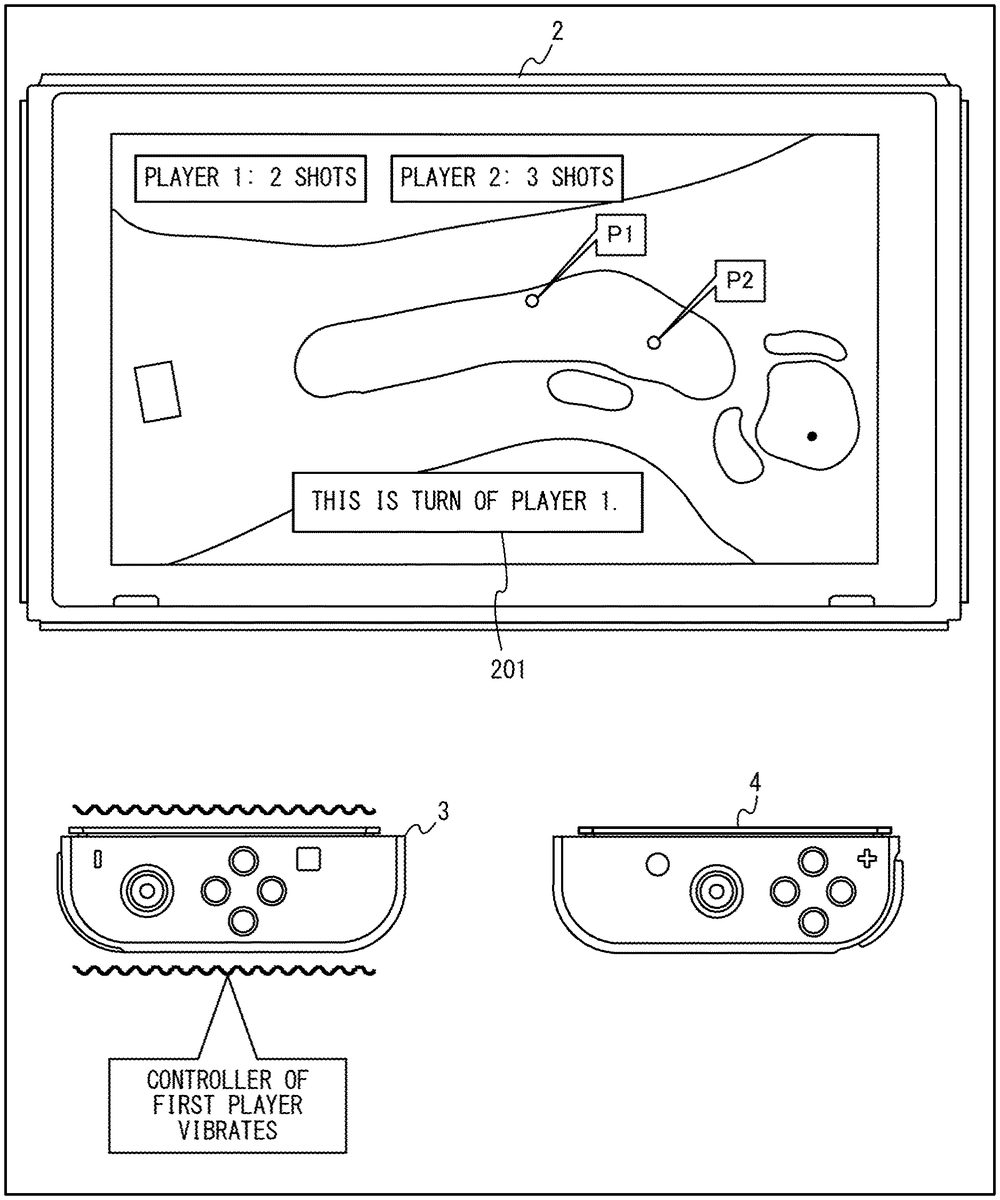
FIG. 8is a diagram showing an example of the state where a controller vibrates during the game. In the exemplary embodiment, two players perform the game, each using a single controller. Specifically, a first player performs the game using the left controller3, and a second player performs the game using the right controller4. At this time, the controllers3and4are used in the state where the controllers3and4are detached from the main body apparatus2.
Although not shown in the figures, in the exemplary embodiment, each of the two players can also perform the game using the game system1(i.e., the main body apparatus2and the controllers3and4). That is, game processing can also be executed by the first player using one game system1, the second player using another game system1, and two main body apparatuses2appropriately communicating with each other. At this time, the controllers3and4can be used in the state where the controllers3and4are detached from the main body apparatus2, or can be used in the state of where the controllers3and4are attached to the main body apparatus2.
[2-1. Vibration of Controller]
In the golf game, the game progresses by each of the players performing a shot operation (i.e., the operation of causing a player character to hit a shot) in order determined in the game (e.g., in descending order of the distance from a cup to a ball). Here, when a player has a turn performing a shot operation, to notify the player of their turn, the game system1vibrates a controller used by the player. For example, in the example shown inFIG. 8, the first player has a turn performing a shot operation. At this time, the game system1vibrates the left controller3associated with the first player. This enables the first player to recognize by the vibration that the first player themselves has a turn performing an operation. Although not shown in the figures, if the second player has a turn performing a shot operation during the game, the game system1vibrates the right controller4associated with the second player. In the example shown inFIG. 8, the display12of the main body apparatus2displays a message201indicating the turn of the first player (“player1” in this game image). In another exemplary embodiment, however, a player may also be notified of their turn by the vibration alone, or by the vibration and a method other than the display (e.g., sound).
In the exemplary embodiment, a player and a controller used by the player are associated with each other at any timing. For example, at the start of the game, the main body apparatus2stores information in which the player and the controller are associated with each other. A specific method for associating the player and the controller is optional.
The form of the vibration (specifically, the intensity, the frequency, the pattern, and the like of the vibration) for the above notification is optional. For example, the game system1controls the controller to repeatedly generate a vibration for a predetermined time at regular intervals from when the game system1enters the state where the game system1receives the shot operation of the player to when the shot operation is started.
In the exemplary embodiment, also at another timing different from the timing when a player has a turn performing a shot operation, the game system1may vibrate a controller. For example, at the timing when a player character operated by a player hits a ball by a shot action, the game system1may vibrate a controller associated with the player. As described above, a vibration may be performed not only for the purpose of giving some notification to a player, but also for the purpose of enhancing the realistic feeling or the sense of immersion of the game. Hereinafter, the timing when a controller should be vibrated during the game will be referred to as a “vibration timing”.
[2-2. Limitation of Control of Vibration]
As described above, in the exemplary embodiment, the game system1vibrates a controller during the game, but limits the vibration of the controller under a certain condition. That is, in the exemplary embodiment, even if the above vibration timing arrives, the game system1limits the vibration of a controller under a certain condition. With reference toFIG. 9, a description is given of the limitation of the vibration of a controller.
FIG. 9is a diagram showing examples of conditions for limiting the vibration of a controller and conditions for cancelling the limitation. Here, in the exemplary embodiment, the game system1determines the state of the motion of a controller (the details of the determination method will be described below). If the state of the motion of the controller is the state where it is determined that the controller is moving (hereinafter referred to as a “moving state”), the vibration of the controller is permitted. That is, in the moving state, the game system1vibrates the controller in accordance with the arrival of the vibration timing. If, on the other hand, the state of the motion of the controller is the state where it is determined that the controller is not moving (hereinafter referred to as a “stopped state”), the vibration of the controller is limited (however, the limitation of the vibration may be cancelled as described below). That is, in the stopped state, even if the vibration timing arrives, the game system1does not vibrate the controller.
In the exemplary embodiment, if the game system1limits the vibration of a controller, the game system1does not vibrate the controller. In another exemplary embodiment, however, the game system1may weaken the vibration of a controller (as compared with a case where the vibration is not limited), thereby limiting the vibration. That is, “limiting the vibration” means that the controller is not vibrated and that the vibration is weakened as compared with a case where the vibration is not limited.
In the present specification, the state where it is determined that a controller is not moving is referred to as the “stopped state”. This state, however, does not need to be the state where the controller is actually completely stopped. If the controller is not actually completely stopped, but is almost stopped, and as a result, the game system1determines that the controller is not moving, it is determined that the controller is in the above “stopped state”.
Here, if it is determined that the state of the motion of a controller is the moving state, it can be presumed that it is likely that a player is holding the controller. Thus, in this case, the game system1vibrates the controller in accordance with the vibration timing and thereby can give a notification to the user or enhance the realistic feeling or the sense of immersion of the game by the vibration.
If, on the other hand, it is determined that the state of the motion of a controller is the stopped state, it can be presumed that it is likely that a player is not holding the controller, and the controller is placed on a table, a floor, or the like. In such a case, the player may have a feeling of discomfort based on the production of a loud sound due to the vibration of an operation device depending on the location where the operation device is placed. Further, in the above case, since the controller is not being held, the purpose of transmitting the vibration of the controller to the player is not achieved. Thus, power consumed by the vibration may go to waste. Thus, in the above case, the game system1limits the vibration of the controller. Consequently, it is possible to reduce the possibility of the occurrence of a disadvantage that a loud sound is produced due to a vibration, or power is consumed by an unnecessary vibration.
In the exemplary embodiment, even if it is determined that the state of the motion of a controller is the stopped state, but if a cancellation condition is satisfied, the game system1cancels the limitation of the vibration (seeFIG. 9). That is, if the cancellation condition is satisfied, the game system1vibrates the controller even in the stopped state. In the exemplary embodiment, the cancellation condition includes the following three conditions, namely first to third cancellation conditions.
The first cancellation condition is that a controller is in the state where the controller is attached to the main body apparatus2. If the controller is in such a state during the game, it can be presumed that a player is using a mobile apparatus obtained by unifying the main body apparatus2and a controller, while holding the mobile apparatus. Thus, if the first cancellation condition is satisfied, the game system1cancels the limitation of the vibration of the controller. As described above, if a controller is attached to the main body apparatus2, the game system1cancels the limitation of vibration control and vibrates the controller in accordance with the vibration timing.
The second cancellation condition is that inputs are provided to the operation sections (specifically, the analog stick and the operation buttons) of a controller. If inputs are provided to the operation sections of the controller, it can be presumed that a player is holding the controller. Thus, if the second cancellation condition is satisfied, the game system1cancels the limitation of the vibration of the controller. As described above, if inputs are provided to the operation sections of a controller, the game system1cancels the limitation of vibration control and vibrates the controller in accordance with the vibration timing.
The third cancellation condition is that the orientation of a controller is not the orientation when the controller is placed on a table, a floor, or the like (hereinafter referred to as a “placement orientation”). Here, in the exemplary embodiment, if a controller is placed on a table, a floor, or the like, it is presumed that the controller is in the orientation in which the main surface of the housing is directed in the vertical up direction. That is, in the exemplary embodiment, the placement orientation is generally the orientation in which the main surface of the housing is directed in the vertical up direction (the details will be described below). If the orientation of the controller is not such a placement orientation, even if the controller is not moving, it can be presumed that the controller is being held by a player without being placed. Thus, if the third cancellation condition is satisfied, the game system1cancels the limitation of the vibration of the controller.
Although the details will be described below, the determination of whether or not the orientation of a controller is the placement orientation is made based on inertia data based on the outputs of inertial sensors (specifically, data based on the output of an acceleration sensor). That is, based on inertia data, the game system1determines whether or not the orientation of a controller satisfies the cancellation condition. If the cancellation condition is satisfied, the game system1cancels the limitation of vibration control.
As described above, in the exemplary embodiment, in a case where it is determined that the state of the motion of a controller is the stopped state, and if the cancellation condition is satisfied, the game system1cancels the limitation of the vibration. Based on this, if a player is holding a controller, it is possible to reduce the possibility that the vibration of the controller is limited.
If at least one of the above first to third cancellation conditions is satisfied, the game system1determines that the cancellation condition is satisfied, and cancels the limitation of the vibration. That is, in the stopped state, if at least one of the first to third cancellation conditions is satisfied, the limitation of the vibration is cancelled. If none of the first to third cancellation conditions is satisfied, the vibration is limited (seeFIG. 9).
In the exemplary embodiment, in the period from when the cancellation condition is satisfied to when a predetermined cancellation continuation time (e.g., 0.5 s) elapses, the game system1cancels the limitation of the vibration. This is because immediately after it is determined that the cancellation condition is satisfied, similarly to the point in time when the cancellation condition is satisfied, it can be presumed that a player is holding the controller. Based on this, for example, it is possible to prevent a failure where immediately after a button input is provided to a controller, the vibration of the controller is suddenly stopped.
[2-3. Determination of State of Motion of Controller]
Next, with reference toFIG. 10, a description is given of a method for determining the state of the motion of a controller (i.e., whether the controller is in the moving state or the stopped state). In the exemplary embodiment, a controller enters either of the above moving state and stopped state. That is, the game system1identifies either of the moving state and the stopped state as the state of the current motion of the controller.
FIG. 10is a diagram illustrating the method for determining the state of the motion of a controller. In the exemplary embodiment, based on an acceleration detected by the acceleration sensor of a controller, the game system1determines the state of the motion of the controller. First, based on the output of the acceleration sensor, the game system1calculates the acceleration of the controller every predetermined unit time (specifically, one frame time). Then, the game system1calculates the amount of change in the acceleration per unit time. In the exemplary embodiment, the amount of change is calculated as a difference D between the acceleration at the current frame and the acceleration at the previous frame. The difference D is obtained by, for example, calculating values obtained by subtracting the values of components (i.e., an x-axis component, a y-axis component, and a z-axis component) of the acceleration at the previous frame from the values of components of the acceleration at the current frame on a component-by-component basis and totaling the absolute values of the subtraction values of the respective components. Thus, if the acceleration at the current frame is A[t], and the acceleration at the previous frame is A[t−1], a difference D[t] at the current frame is calculated by the following formula (1).
D[t]=|Ax[t]−Ax[t−1]|+|Ay[t]−Ay[t−1]|+|Az[t]−Az[t−1]| (1)
The game system1calculates the above difference D every unit time.
Next, the game system1calculates the total value of the differences D calculated in the period from the current frame to a predetermined difference calculation time (here, a time corresponding to eight frames) before. In the exemplary embodiment, the game system1calculates the total value of the differences at the most recent eight frames including the current frame (i.e., D[t], D[t−1], . . . , D[t−7]) (seeFIG. 10). Then, based on the above total value, the game system1determines whether the controller is in the moving state or the stopped state. In the exemplary embodiment, if the controller is in the moving state, and if the total value falls below a predetermined lower limit threshold, the game system1changes the result of the determination as the motion of the controller from the moving state to the stopped state. If the controller is in the stopped state, and if the total value exceeds a predetermined upper limit threshold, the game system1changes the controller from the stopped state to the moving state. The upper limit threshold is set to a value greater than the lower limit threshold. This can reduce the possibility that the turning on and off of the vibration of the controller is frequently repeated by the frequent switching of the moving state and the stopped state.
As described above, in the exemplary embodiment, if the magnitude of a change in an acceleration detected by the acceleration sensor in a predetermined period (i.e., the period from the current moment to the difference calculation time before) is smaller than a reference, the game system1determines that the controller is not moving. Based on this, even if a controller is not completely stopped, but is substantially stopped, the game system1can determine that the controller is not moving. Here, if the vibration of a controller is limited only when the controller is completely stopped, there will be too few situations where the vibration is limited, and the vibration may not be able to be effectively limited. In contrast, according to the exemplary embodiment, if a controller is substantially stopped, the vibration of the controller can be limited. Thus, the vibration can be effectively limited. In the exemplary embodiment, the above “reference” is the above lower limit value or upper limit value. Thus, the value of the reference changes. In another exemplary embodiment, however, the above “reference” may be a fixed value.
The method for determining the state of the motion of a controller is optional. For example, in another exemplary embodiment, based on whether or not the magnitude of the current acceleration of a controller is greater than or equal to a threshold, the game system1may determine whether the controller is in the moving state or the stopped state. In another exemplary embodiment, based on an angular velocity detected by the angular velocity sensor together with (or instead of) an acceleration detected by the acceleration sensor, the game system1may make the above determination.
[2-4. Determination of Whether or not Orientation is Placement Orientation]
Next, with reference toFIG. 11, a description is given of a method for determining whether or not the orientation of a controller is the placement orientation. Here, in the exemplary embodiment, the orientation when the main surface of the housing of a controller is directed in the vertical up direction (i.e., a straight line perpendicular to the main surface is parallel to the vertical up direction) is defined as a reference orientation, and the placement orientation refers to an orientation within a predetermined range from the reference orientation.
FIG. 11is a diagram showing an example of a case where it is determined that the orientation of a controller is the placement orientation, and an example of a case where it is determined that the orientation of the controller is not the placement orientation. InFIG. 11, an acceleration vector A represents the acceleration of the controller detected by the acceleration sensor. In the examples shown inFIG. 11, the controller is stopped, and only a gravitational acceleration is applied to the controller.
In the exemplary embodiment, the game system1makes a determination based on the y-component Ay and the z-component Az of the above acceleration vector A. Here, as shown inFIG. 11, if a value obtained by doubling the y-component Ay of the acceleration vector A is less than or equal to the z-component Az ((a) ofFIG. 11), the orientation of the controller is close to the reference orientation. If, on the other hand, the value obtained by doubling the y-component Ay of the acceleration vector A is greater than the z-component Az ((b) ofFIG. 11), the orientation of the controller is far from the reference orientation. Thus, in the exemplary embodiment, in the first case, the game system1determines that the orientation of the controller is the placement orientation. In the second case, the game system1determines that the orientation of the controller is not the placement orientation. Although in the exemplary embodiment, the value obtained by doubling the y-component Ay of the acceleration vector A is used in the above determination, the value of a coefficient by which to multiply the y-component Ay is optional.
The method for determining whether or not the orientation of a controller is the placement orientation is optional. The determination may be made by another method. For example, in another exemplary embodiment, based on whether or not the angle between the acceleration vector A and the z-axis direction is less than or equal to a predetermined value, the game system1may determine whether or not the orientation of the controller is the placement orientation. In another exemplary embodiment, based on an angular velocity detected by the angular velocity sensor together with (or instead of) an acceleration detected by the acceleration sensor, the game system1may make the above determination. The inertial sensors used to determine whether or not the orientation of a controller is the placement orientation and the inertial sensors used to determine the state of the motion of the controller may be the same as or different from each other.
[3. Specific Example of Processing in Game System]
Next, with reference toFIGS. 12 and 13, a description is given of a specific example of the information processing in the game system1.
FIG. 12is a diagram showing examples of various pieces of data used for the information processing in the game system1. The various pieces of data shown inFIG. 12are stored in a storage medium (e.g., the flash memory84, the DRAM85, a memory card attached to the slot23, and/or the like) accessible by the main body apparatus2.
As shown inFIG. 12, the game system1stores a game program. The game program is a game program for executing the game according to the exemplary embodiment (specifically, game program processing shown inFIG. 13). The game system1stores operation data, amount-of-change data, controller state data, and cancellation flag data.
As described above, the operation data is transmitted from each of the controllers3and4to the main body apparatus2and stored in the main body apparatus2. In the exemplary embodiment, the operation data includes input data indicating inputs to the above operation sections, and acceleration data based on the output of the acceleration sensor of the controller. The amount-of-change data indicates the amount of change in an acceleration per unit time of a controller, and in the exemplary embodiment, indicates the above difference D. In the exemplary embodiment, the main body apparatus2saves, as the amount-of-change data, data indicating the difference D calculated at least in the period from the current time to the above difference calculation time before. The controller state data indicates the state of the motion of a controller, and in the exemplary embodiment, indicates either of the moving state and the stopped state. The cancellation flag data is data of a flag indicating whether or not the current state is the state where the limitation of the vibration is cancelled. Although not shown in the figures, the main body apparatus2stores each of the operation data, the amount-of-change data, the controller state data, and the cancellation flag data with respect to each controller used in the game.
FIG. 13is a flow chart showing an example of the flow of game program processing executed in the game system1. The game program processing shown inFIG. 13is started in accordance with the fact that, for example, a player gives a predetermined game start instruction during the execution of the above game program.
In the exemplary embodiment, the description is given on the assumption that the processes of steps shown inFIG. 13are executed by the processor81of the main body apparatus2executing the game program stored in the game system1. In another exemplary embodiment, however, some of the processes of the above steps may be executed by a processor (e.g., a dedicated circuit or the like) different from the processor81. Further, in a case where the game system1can communicate with another information processing apparatus (e.g., a server), some of the processes of the steps shown inFIG. 13may be executed by the other information processing apparatus. The processes of all of the steps shown inFIG. 13are merely illustrative. Thus, the processing order of the steps may be changed, or another process may be performed in addition to (or instead of) the processes of all of the steps, so long as similar results are obtained.
The processor81executes the processes of the steps shown inFIG. 13, using a memory (e.g., the DRAM85). That is, the processor81stores information (in other words, data) obtained by each processing step in the memory. To use the information in the subsequent processing steps, the processor81reads the information from the memory and uses the read information.
In step S1shown inFIG. 13, the processor81acquires operation data from each controller. That is, the processor81acquires operation data received from each controller via the controller communication section83and/or the terminals17and21and stores the operation data in the memory. After step S1, the process of step S2is executed.
In step S2, the processor81executes game processing for advancing the game. For example, in accordance with an input provided by the player (i.e., based on the operation data acquired in step S1), the processor81executes the process of causing a player character to perform an action in a virtual game space, or the process of causing an object (e.g., a ball) to perform an action in the game space. The processor81generates a game image representing the game space and displays the game image on the display12. In the exemplary embodiment, the process of step S2is executed repeatedly, once every predetermined frame time. After step S2, the process of step S3is executed.
In step S3, the processor81determines the state of the motion of the controller. Specifically, in accordance with the method described in the above “[2-3. Determination of State of Motion of Controller]”, and based on the acceleration data acquired in step S1, the processor81determines whether the controller is in the moving state or the stopped state. At this time, the processor81stores data indicating the calculated current difference D as amount-of-change data in the memory. The processor81stores data indicating the determined state as controller state data in the memory. In the period from when the game program processing shown inFIG. 13is started to when the described difference calculation time elapses, the determination cannot be made by the above method. Thus, in this period, the state of the motion of the controller is set to one of the moving state and the stopped state determined in advance by the game program. After step S3, the process of step S4is executed.
In step S4, the processor81determines whether or not the vibration timing arrives. The determination in step S4is made based on the game situation resulting from the advancement in the process of step S2. For example, if any of players participating in the game enters the state where the player performs a shot operation, or if a player character hits a ball, the processor81determines that the vibration timing arrives. If the result of the determination in step S4is affirmative, the process of step S5is executed. If, on the other hand, the result of the determination in step S4is negative, the series of processes of steps S5to S9is skipped, and the process of step S10described below is executed.
In step S5, based on the controller state data stored in the memory, the processor81determines whether or not the state of the motion of the controller is the stopped state. If the result of the determination in step S5is affirmative, the process of step S6is executed. If, on the other hand, the result of the determination in step S5is negative, the process of step S9described below is executed.
In step S6, the processor81determines whether or not the cancellation condition is satisfied. That is, the processor81determines whether or not any of the above first to third cancellation conditions is satisfied. The determination regarding the first cancellation condition is made based on the communication state between the controller and the main body apparatus2(i.e., whether the communication is wireless communication or wired communication). The determination regarding the second cancellation condition is made based on the input data acquired in step S1. The determination regarding the third cancellation condition is made in accordance with the method described in the above “[2-4. Determination of Whether or not Orientation Is Placement Orientation]” and based on the acceleration data acquired in step S1. If the result of the determination in step S6is affirmative, the process of step S7is executed. If, on the other hand, the result of the determination in step S6is negative, the process of step S8is executed.
In step S7, the processor81cancels the limitation of the vibration of the controller. Specifically, the processor81updates a cancellation flag data stored in the memory to a content indicating an on state (i.e., the state where the limitation of the vibration is cancelled). In the exemplary embodiment, if the above cancellation continuation time elapses since the result of the determination is affirmative in step S6for the last time, the processor81updates the cancellation flag data to indicate an off state (i.e., the state where the limitation of the vibration is not cancelled). After step S7, the process of step S9is executed.
In step S8, the processor81determines whether or not the current time is in a cancellation continuation period. That is, the processor81determines whether or not the cancellation flag data stored in the memory indicates the on state. If the result of the determination in step S8is affirmative, the process of step S9is executed. If, on the other hand, the result of the determination in step S8is negative, the process of step S10is executed.
As described above, in the exemplary embodiment, if it is determined that the state of the motion of the controller is the stopped state (Yes in step S5), and the cancellation condition is not satisfied, and the current time is not the cancellation continuation period (No in steps S6and S8), the process of controlling the vibration (step S9) is not executed. That is, control of the vibration is limited.
In step S9, the processor81controls the vibration of the controller. Specifically, the processor81generates the above vibration control signal for vibrating the vibrator of the specified controller and causes the controller communication section83to perform the operation of transmitting the vibration control signal to the controller. The controller having received the vibration control signal (specifically, the communication control section) outputs a control signal corresponding to the vibration control signal to an amplifier, thereby vibrating the vibrator. Consequently, the vibrator vibrates in a vibration form specified by the vibration control signal, and the controller vibrates. After step S9, the process of step S10is executed.
In step S10, the processor81determines whether or not the game is to be ended. Specifically, if a predetermined ending condition (e.g., the fact that play in a predetermined number of golf courses ends) is satisfied, or if an instruction to end the game is given by the player, the processor81determines that the game is to be ended. If the result of the determination in step S10is negative, the process of step S1is executed again. From this time onward, the series of processes of steps S1to S10is repeatedly executed until it is determined in step S10that the game is to be ended. If, on the other hand, the result of the determination in step S10is affirmative, the processor81ends the game program processing shown inFIG. 13.
[4. Effects and Variations of Above Exemplary Embodiment]
In the above exemplary embodiment, the game system1includes an information processing apparatus (e.g., the main body apparatus2) and at least one operation device (e.g., controller). The information processing apparatus includes a processor, and the operation device includes an inertial sensor (e.g., an acceleration sensor) and a vibrator. The operation device transmits inertia data (e.g., acceleration data) based on the output of the inertial sensor to the information processing apparatus and vibrates the vibrator based on a vibration control signal received from the information processing apparatus. The processor (a) executes game processing (e.g., step S2), (b) in a predetermined situation in game processing, causes a vibration control signal for vibrating the vibrator of the specified operation device to be output from the information processing apparatus (e.g., step S9), (c) based on inertia data from the operation device, determines whether or not the operation device is moving (e.g., steps S3and S5), and (d) at least under the condition that it is determined that the operation device is not moving, limits the vibration so that the vibrator of the operation device is not vibrated (or the vibration is weakened) in the predetermined situation (e.g., the process of step S9is skipped at least under the condition that the determination is Yes in step S5).
Based on the above, if it is presumed that the operation device is placed without being held by a player, it is possible to limit the vibration of the operation device. Consequently, it is possible to reduce the possibility of the occurrence of a disadvantage that a loud sound is produced due to the vibration of a controller placed on a table or a floor, or power is consumed by an unnecessary vibration.
The above “inertia data based on the outputs of inertial sensors” may be data itself output from the inertial sensors, or data obtained by performing some process (e.g., the process of converting the data format, a calculation process, or the like) on data output from the inertial sensors.
The above “predetermined situation” may be any situation during the game. In the above exemplary embodiment, the processor executes a game (e.g., a golf game) where a plurality of players perform game operations in order in game processing. Then, as the predetermined situation, in a situation where a player has a turn performing a game operation, vibration control is performed. Specifically, at least under the condition that it is determined that in the above situation, an operation device corresponding to the player is moving, the processor81outputs from the information processing apparatus a vibration control signal for vibrating the vibrator of the operation device (FIG. 8), and at least under the condition that it is determined that the operation device is not moving, limits vibration control. Based on the above, if a player having a turn performing an operation is holding an operation device during a multiplay game, it is possible to give a notification to the player by a vibration, and also, if the player is not holding the operation device, it is possible to reduce the possibility of the occurrence of a disadvantage due to a vibration.
The game executed by the game system1may be not only a multiplay game in which a plurality of players participate, but also a game executed by a single player. In the game executed by a single player, the above “predetermined situation” is, for example, a situation where a controller vibrates in accordance with the content of a moving image in the period when a moving image is reproduced during the game (e.g., a situation where the controller vibrates in accordance with an explosion scene). In the period when the moving image is reproduced as described above, there is a possibility that the player places the controller on a table or a floor. Thus, the above exemplary embodiment is applied in a situation as described above, it is possible to achieve effects similar to those of the above exemplary embodiment.
(Variations Regarding Limitation of Vibration)
In the above exemplary embodiment, in a case where it is determined that a controller is not moving, and if the cancellation condition is satisfied, the limitation of the vibration is cancelled. Here, in another exemplary embodiment, the cancellation condition may not be set, and if it is determined that the controller is not moving, the vibration of the controller may be limited. At this time, if it is determined that the controller is not moving, and if a predetermined easing condition is satisfied, the game system1may weaken the vibration of the controller as compared with a case where the vibration is not limited. If the easing condition is not satisfied, the game system1may not vibrate the controller. That is, in a case where it is determined that the controller is not moving, the game system1may vary a method for limiting the vibration (i.e., whether the vibration is to be stopped or weakened) based on whether or not a condition is satisfied.
As the above easing condition, a condition opposite to the above cancellation condition may be used. For example, the condition that “the orientation of the controller is the placement orientation”, which is a condition opposite to the above third cancellation condition, may be used as the easing condition. Here, if it is determined that a controller is not moving, and if it is determined that the orientation of the controller is the above placement orientation, it can be estimated that it is likely that the controller is placed on a table or a floor, but it is also possible that the controller is being held by a player in the orientation in which the controller is in the placement orientation. Thus, in a case where it is determined that a controller is not moving, and if it is determined that the orientation of the controller is the above placement orientation, the game system1may weaken the vibration of the controller. Based on this, the vibration of the controller is weakened. Thus, even if the controller is actually placed, it is possible to reduce the possibility of the occurrence of a disadvantage due to a vibration. Further, even if the controller is actually being held by a player, it is possible to transmit a vibration to the player. In a case where it is determined that a controller is not moving, and if the easing condition is not satisfied (i.e., if it is determined that the orientation of the controller is not the placement orientation), the game system1does not vibrate the controller, whereby it is possible to certainly reduce the possibility of the occurrence of a disadvantage due to a vibration.
In another exemplary embodiment, the game system1may use both the cancellation condition and the easing condition. For example, in a case where it is determined that a controller is not moving, the game system1(a) may cancel the limitation of the vibration if the above first cancellation condition (i.e., a controller is in the state where the controller is attached to the main body apparatus2) is satisfied, (b) may weaken the vibration if the above easing condition is satisfied, and (c) may not vibrate the controller if neither the first cancellation condition and the above easing condition is satisfied.
In another exemplary embodiment, in accordance with the type of vibration, the game system1may switch whether or not to limit the vibration. For example, regarding a first type of vibration for the purpose of enhancing the realistic feeling or the sense of immersion of the game, if a condition is satisfied, the game system1may limit the vibration. On the other hand, regarding a second type of vibration for the purpose of giving a notification to a player, even if the condition is satisfied, the game system1may not limit the vibration. The first type of vibration is, for example, a vibration corresponding to a sound effect in the game, or a vibration corresponding to the action of a game object. The second type of vibration is, for example, a vibration for notifying a player that the player has a turn operating an operation, or a vibration for notifying a player of the location of a controller (when the player loses sight of the controller). Consequently, it is possible to reduce the possibility of the occurrence of a disadvantage due to a vibration and also certainly give a notification to a player.
(Variations Regarding Condition for Limiting Vibration)
In the above exemplary embodiment, at least under the condition that it is determined that a controller is not moving, the vibration of the controller is limited. Here, in another exemplary embodiment, regardless of whether or not a controller is moving, at least under the condition that it is determined that the controller is not in the above placement orientation, the game system1may limit the vibration of the controller. As described above, based on inertia data, the game system1may determine whether or not the orientation of a controller satisfies a predetermined condition, and at least under the condition that the predetermined condition is satisfied, may limit the vibration of the controller. At this time, the game system1may use “the determination that the controller is moving” as the cancellation condition.
(Variations Regarding Configuration of Game System)
In the above exemplary embodiment, the game system1includes the main body apparatus2and a controller attachable to and detachable from the main body apparatus2. In another exemplary embodiment, the game system may include a single apparatus. For example, the game system may be an information processing apparatus obtained by unifying the main body apparatus2and the controllers3and4, and may be a mobile information processing apparatus including an inertial sensor and a vibrator. At this time, the above first cancellation condition is not used.
The above exemplary embodiment can be used for, for example, a game system and a game program in order, for example, to reduce the possibility of the occurrence of a disadvantage due to the vibration of an operation device.
While certain example systems, methods, devices and apparatuses have been described herein, it is to be understood that the appended claims are not to be limited to the systems, methods, devices and apparatuses disclosed, but on the contrary, are intended to cover various modifications and equivalent arrangements included within the spirit and scope of the appended claims.
Claims
- A game system comprising: an information processing apparatus;and at least one operation device, wherein the information processing apparatus includes one or more processors, the at least one operation device includes an inertial sensor and a vibrator and is configured to: transmit inertia data based on an output of the inertial sensor to the information processing apparatus;and vibrate the vibrator based on a vibration control signal received from the information processing apparatus, the one or more processors are configured to: execute game processing;in a predetermined situation in the game processing, cause the vibration control signal to be output from the information processing apparatus;based on the inertia data from the at least one operation device, determine whether or not the at least one operation device is moving;at least under the condition that it is determined that the at least one operation device is not moving, limit a vibration so that the vibrator of the at least one operation device is not vibrated or the vibration is weakened in the predetermined situation;and based on the inertia data, determine whether or not an orientation of the at least one operation device satisfies a cancellation condition, including (a) determining that the orientation of the at least one operation device satisfies the cancellation condition and (b) cancelling the limit of the vibration, when the orientation of the at least one operation device is an orientation different from a placement orientation.
- The game system according to claim 1 , wherein the inertial sensor includes at least an acceleration sensor, and if a magnitude of a change in an acceleration detected by the acceleration sensor in a predetermined period is smaller than a reference, the one or more processors determine that the at least one operation device is not moving.
- The game system according to claim 1 , wherein the at least one operation device further includes an operation button and/or a direction input stick, and if an input is provided to the operation button and/or the direction input stick, the one or more processors further cancel the limitation of the vibration.
- The game system according to claim 1 , wherein the one or more processors: execute a game where a plurality of players perform game operations in order in the game processing;and in a situation where a player has a turn performing a game operation, at least under the condition that it is determined that the at least one operation device corresponding to the player is moving, cause the vibration control signal to be output from the information processing apparatus, and at least under the condition that it is determined that the at least one operation device is not moving, limit the vibration.
- A game system comprising: an information processing apparatus;and at least one operation device, wherein the information processing apparatus includes one or more processors, the at least one operation device includes an inertial sensor and a vibrator and is configured to: transmit inertia data based on an output of the inertial sensor to the information processing apparatus;and vibrate the vibrator based on a vibration control signal received from the information processing apparatus, the one or more processors are configured to: execute game processing;in a predetermined situation in the game processing, cause the vibration control signal to be output from the information processing apparatus;based on the inertia data from the at least one operation device, determine whether or not the at least one operation device is moving;at least under the condition that it is determined that the at least one operation device is not moving, limit a vibration so that the vibrator of the at least one operation device is not vibrated or the vibration is weakened in the predetermined situation;and wherein the at least one operation device is attachable to the information processing apparatus, and if the at least one operation device is in a state where the at least one operation device is attached to the information processing apparatus, the one or more processors further cancel the limitation of the vibration.
- The game system according to claim 5 , wherein the at least one operation device further includes an operation button and/or a direction input stick, and if an input is provided to the operation button and/or the direction input stick, the one or more processors further cancel the limitation of the vibration.
- The game system according to claim 5 , wherein the one or more processors: execute a game where a plurality of players perform game operations in order in the game processing;and in a situation where a player has a turn performing a game operation, at least under the condition that it is determined that the at least one operation device corresponding to the player is moving, cause the vibration control signal to be output from the information processing apparatus, and at least under the condition that it is determined that the at least one operation device is not moving, limit the vibration.
- A non-transitory computer-readable storage medium having stored therein a game program causing one or more processors of an information processing apparatus to: communicate with an operation device including an inertial sensor and a vibrator and configured to transmit inertia data based on an output of the inertial sensor to the information processing apparatus and vibrate the vibrator based on a vibration control signal received from the information processing apparatus;execute game processing;in a predetermined situation in the game processing, cause the vibration control signal to be output from the information processing apparatus;based on the inertia data from the operation device, determine whether or not the operation device is moving;at least under the condition that it is determined that the operation device is not moving, limit a vibration so that the vibrator of the operation device is not vibrated or the vibration is weakened in the predetermined situation;and based on the inertia data, determine whether or not an orientation of the at least one operation device satisfies a cancellation condition, including (a) determining that the orientation of the at least one operation device satisfies the cancellation condition and (b) cancelling the limit of the vibration, when the orientation of the at least one operation device is an orientation different from a placement orientation.
- The non-transitory computer readable storage medium according to claim 8 , wherein the inertial sensor includes at least an acceleration sensor, and the game program causes the computer to, if a magnitude of a change in an acceleration detected by the acceleration sensor in a predetermined period is smaller than a reference, determine that the operation device is not moving.
- The non-transitory computer readable storage medium according to claim 8 , wherein the operation device further includes an operation button and/or a direction input stick, and the game program causes the computer to, if an input is provided to the operation button and/or the direction input stick, cancel the limitation of the vibration.
- The non-transitory computer readable storage medium according to claim 8 , wherein the operation device is attachable to the information processing apparatus, and the game program causes the computer to if the operation device is in a state where the operation device is attached to the information processing apparatus, cancel the limitation of the vibration.
- The non-transitory computer readable storage medium according to claim 8 , wherein the game program causes the computer to: execute a game where a plurality of players perform game operations in order in the game processing;and in a situation where a player has a turn performing a game operation, at least under the condition that it is determined that the operation device corresponding to the player is moving, cause the vibration control signal for vibrating the vibrator of the operation device to be output from the information processing apparatus, and at least under the condition that it is determined that the operation device is not moving, limit the vibration.
- An information processing apparatus comprising one or more processors configured to: communicate with an operation device including an inertial sensor and a vibrator and configured to transmit inertia data based on an output of the inertial sensor to the information processing apparatus and vibrate the vibrator based on a vibration control signal received from the information processing apparatus;execute game processing;in a predetermined situation in the game processing, cause the vibration control signal to be output from the information processing apparatus;based on the inertia data from the operation device, determine whether or not the operation device is moving;and at least under the condition that it is determined that the operation device is not moving, limit a vibration so that the vibrator of the operation device is not vibrated or the vibration is weakened in the predetermined situation;and based on the inertia data, determine whether or not an orientation of the at least one operation device satisfies a cancellation condition, including (a) determining that the orientation of the at least one operation device satisfies the cancellation condition and (b) cancelling the limit of the vibration, when the orientation of the at least one operation device is an orientation different from a placement orientation.
- The information processing apparatus according to claim 13 , wherein the inertial sensor includes at least an acceleration sensor, and if a magnitude of a change in an acceleration detected by the acceleration sensor in a predetermined period is smaller than a reference, the one or more processors determine that the operation device is not moving.
- The information processing apparatus according to claim 13 , wherein the operation device further includes an operation button and/or a direction input stick, and if an input is provided to the operation button and/or the direction input stick, the one or more processors further cancel the limitation of the vibration.
- The information processing apparatus according to claim 13 , wherein the operation device is attachable to the information processing apparatus, and if the operation device is in a state where the operation device is attached to the information processing apparatus, the one or more processors further cancel the limitation of the vibration.
- The information processing apparatus according to claim 13 , wherein the one or more processors: execute a game where a plurality of players perform game operations in order in the game processing;and in a situation where a player has a turn performing a game operation, at least under the condition that it is determined that the operation device corresponding to the player is moving, cause the vibration control signal to be output from the information processing apparatus, and at least under the condition that it is determined that the operation device is not moving, limit the vibration.
- A game processing method executed in a game system including an information processing apparatus and at least one operation device including an inertial sensor and a vibrator, wherein the at least one operation device is configured to transmit inertia data based on an output of the inertial sensor to the information processing apparatus, the information processing apparatus is configured to: execute game processing;and in a predetermined situation in the game processing, output a vibration control signal for vibrating the vibrator of the at least one operation device, the at least one operation device is configured to vibrate the vibrator based on the vibration control signal received from the information processing apparatus, and the information processing apparatus is configured to: based on the inertia data from the at least one operation device, determine whether or not the at least one operation device is moving;at least under the condition that it is determined that the at least one operation device is not moving, limit a vibration so that the vibrator of the at least one operation device is not vibrated or the vibration is weakened in the predetermined situation;and based on the inertia data, determine whether or not an orientation of the at least one operation device satisfies a cancellation condition, including (a) determining that the orientation of the at least one operation device satisfies the cancellation condition and (b) cancelling the limit of the vibration, when the orientation of the at least one operation device is an orientation different from a placement orientation.
- The game processing method according to claim 18 , wherein the inertial sensor includes at least an acceleration sensor, and if a magnitude of a change in an acceleration detected by the acceleration sensor in a predetermined period is smaller than a reference, the information processing apparatus determines that the at least one operation device is not moving.
- The game processing method according to claim 18 , wherein the at least one operation device further includes an operation button and/or a direction input stick, and if an input is provided to the operation button and/or the direction input stick, the information processing apparatus further cancels the limitation of the vibration.
- The game processing method according to claim 18 , wherein the at least one operation device is attachable to the information processing apparatus, and if the at least one operation device is in a state where the at least one operation device is attached to the information processing apparatus, the information processing apparatus further cancels the limitation of the vibration.
- The game processing method according to claim 18 , wherein the information processing apparatus: executes a game where a plurality of players perform game operations in order in the game processing;and in a situation where a player has a turn performing a game operation, at least under the condition that it is determined that the at least one operation device corresponding to the player is moving, outputs the vibration control signal and at least under the condition that it is determined that the at least one operation device is not moving, limits the vibration.
- An information processing apparatus comprising one or more processors, an inertial sensor, and a vibrator, wherein the one or more processors are configured to: execute game processing;in a predetermined situation in the game processing, vibrate the vibrator;based on an output of the inertial sensor, determine whether or not the information processing apparatus is moving;at least under the condition that it is determined that the information processing apparatus is not moving, limit a vibration so that the vibrator is not vibrated or the vibration is weakened in the predetermined situation;and based on the inertia data, determine whether or not an orientation of the information processing device satisfies a cancellation condition, including (a) determining that the orientation of the information processing device satisfies the cancellation condition and (b) cancelling the limit of the vibration, when the orientation of the information processing device is an orientation different from a placement orientation.
- The game system according to claim 5 , wherein the inertial sensor includes at least an acceleration sensor, and if a magnitude of a change in an acceleration detected by the acceleration sensor in a predetermined period is smaller than a reference, the one or more processors determine that the at least one operation device is not moving.
Disclaimer: Data collected from the USPTO and may be malformed, incomplete, and/or otherwise inaccurate.