U.S. Pat. No. 11,325,030
GAME PAD HOLDER FOR VIRTUAL REALITY VIDEO GAMES, COMPRISING A MECHANICAL FORCE FEEDBACK DEVICE
AssigneePROTUBEVR
Issue DateMarch 16, 2021
Illustrative Figure
Abstract
A game pad holder for video games adapted to simulate a weapon, the holder has a mechanical force feedback device designed to simulate the recoil of the weapon at the moment of a trigger pressure during a game event, and the force feedback device includes: a casing in the form of a butt in physical contact with a zone of the body of the player, a firing pin forming a physical contact with the zone of the body of the player, and the firing pin is mounted mobile in the casing between: a folding position, and an advanced position to impact the zone of the body of the player. The device further includes a spring element, an actuator and an electronic management unit so that only pressure exerted on the firing pin the player allows to make the firing pin to pass from an advanced position to the folding position.
Description
DETAILED DESCRIPTION OF THE EMBODIMENTS The invention implements one or more computer applications executed by the force feedback device. For clarity, it must be understood, in the sense of the invention, that “the device does something” means “the computer application executed by the processor or microprocessor of the device does something”. Just like “the computer application does something” means “the computer application executed by the processor or microprocessor of the device does something”. Also for clarity, the present invention can make reference to one or more “logical computer processes”. The latter correspond to the actions or results obtained by the execution of instructions of different computer applications. Also, it must also be understood in the sense of the invention that “a logical computer process is adapted to do something” means “the instructions of a computer application executed by a processor or microprocessor do something”. Also for clarity, the following precisions are applied to certain terms used in the description and the claims: “Computer resource” can be understood in a non-limiting manner, as: component, equipment, software, file, connection to a computer network, quantity of RAM, hard disk space, bandwidth, processor speed, CPU number, hardware, etc. “Software” can be understood as: computer application, computer program or software. “Electronic management unit” can be understood in a non-limiting manner, as: processor, microprocessor, CPU (Central Processing Unit). “Video game” can be understood as an electronic game provided with a user interface allowing a fun or non-fun human interaction (e.g. shooting training simulation) by generating a visual return on a video device (screen, headset, glasses, etc.). “A and/or B” means: only A or only B or A+B. The force feedback device according to the invention is intended to be equipped with a video game accessory. This accessory can be a controller (game controller), a game pad ...
DETAILED DESCRIPTION OF THE EMBODIMENTS
The invention implements one or more computer applications executed by the force feedback device. For clarity, it must be understood, in the sense of the invention, that “the device does something” means “the computer application executed by the processor or microprocessor of the device does something”. Just like “the computer application does something” means “the computer application executed by the processor or microprocessor of the device does something”.
Also for clarity, the present invention can make reference to one or more “logical computer processes”. The latter correspond to the actions or results obtained by the execution of instructions of different computer applications. Also, it must also be understood in the sense of the invention that “a logical computer process is adapted to do something” means “the instructions of a computer application executed by a processor or microprocessor do something”.
Also for clarity, the following precisions are applied to certain terms used in the description and the claims:
“Computer resource” can be understood in a non-limiting manner, as: component, equipment, software, file, connection to a computer network, quantity of RAM, hard disk space, bandwidth, processor speed, CPU number, hardware, etc.
“Software” can be understood as: computer application, computer program or software.
“Electronic management unit” can be understood in a non-limiting manner, as: processor, microprocessor, CPU (Central Processing Unit).
“Video game” can be understood as an electronic game provided with a user interface allowing a fun or non-fun human interaction (e.g. shooting training simulation) by generating a visual return on a video device (screen, headset, glasses, etc.).
“A and/or B” means: only A or only B or A+B.
The force feedback device according to the invention is intended to be equipped with a video game accessory. This accessory can be a controller (game controller), a game pad holder (simulating a weapon such as a pistol, an assault rifle or a sword, a golfclub, a tennis racket, a fishing rod), an item of clothing, etc.
The device allows to simulate a physical impact during a virtual or non-virtual video game event. It allows, for example, to simulate the recoil of a weapon at the moment of a trigger pressure (e.g. in the case of a pistol or of an assault rifle), a contact with another virtual object (e.g. a contact with the sword of an enemy or with a golf or tennis ball, the catching of a fish with a fishing rod, etc.), a bullet impact (e.g. in the case of an item of clothing integrating one or more force feedback devices).
For clarity and conciseness, below the description describes the force feedback device associated with a controller support. The same force feedback device can of course be integrated in another video game accessory.
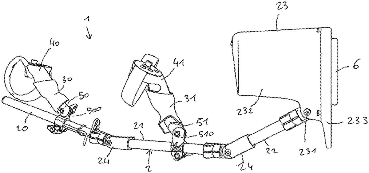
InFIGS. 1 and 2, the game pad holder1is presented in the form of a stick. This stick2simulates an object in a video game virtual environment, in particular a rifle, but also other objects such as a handgun, sword, stick, golfclub, fishing rod, etc. In other words, the stick2forms a virtual simulated object. In a virtual reality environment, the player does not see what they have between their hands. A single holder allowing to hold controllers aligned appears fully sufficient.
The stick2can be straight, curved or be presented in the form of a broken line. It has, in particular, the function of physically connecting the controllers together and to hold them in a certain alignment.
According to the preferred embodiment illustrated inFIGS. 1 and 2, the stick2has four portions20,21,22,23articulated together: a front portion20, a middle portion21, a rear portion22and a butt23. An advantage linked to the use of an articulated stick2is that this can be easily folded, and that in this folded state, the holder1has a reduced size such that it can be easily stored and/or transported. Furthermore, the player has the possibility to shape the stick2to adapt it to the morphology thereof and/or to the type of virtual simulated object used in the video game.
The front20, middle21and rear22portions are advantageously presented in the form of rigid tubes, made of metal, plastic, wood, carbon, etc. The tubes can be cylindrical, of round, oval, square, rectangular, etc., cross-section. The length thereof is, for example, comprised between 15 cm and 30 cm and the outer diameter thereof, for example, comprised between 1 cm and 5 cm. These portions can have the same length or different lengths.
The portions20,21and22are advantageously connected together by means of articulated tube connectors24with two junctions. These connectors24each form a horizontal axis pivot connection. The articulations of the connectors24are preferably notched such that the player can adjust the shape of the stick2to suit, then lock the portions20,21and22in position once the shape is made.
The butt23can be made of the same material as the articulated portions20,21,22,23or of a different material. To simplify the design thereof, it is obtained by plastic molding. InFIGS. 1 and 2, this butt23is mounted on an articulation231. The main body232of the butt23is oriented along the same direction as the stick2, to the front portion20. The rear portion233is intended to abut against the shoulder of the player and the branch232forms a cheek holder particularly useful for the player when they want to adjust a shot.
The articulation231forms a horizontal axis pivot connection enabling a rotation of the butt23with respect to the axis of the stick2. Here, “axis of the stick” means the longitudinal axis of the stick2when it is rectilinear, or the longitudinal axis of the rear portion22when said stick is not rectilinear. The articulation231is presented preferably in the form of a notched articulation allowing the player to adjust the inclination of the butt23to suit, then to lock it in position once this adjustment is made. In any case, the butt23is removably fixed onto the stick2such that the player can remove it or change it if needed.
The holder1is provided with two housings30,31adapted to each receive a controller40,41. These housings30,31can be made of metal, plastic, carbon, etc. InFIGS. 1 and 2, they are disposed on the front20and middle21portions of the stick2.
The controllers40,41are of the known type. They generally comprise a joystick or touchpad for the movements of the player in the virtual environment, one or more buttons and/or triggers allowing to trigger actions in this environment and in particular, the picking up/putting down of objects, taking photos, aiming, shooting, etc. Different movement and/or position sensors are disposed on a crown integral with the handle of the controller. They are, for example, commercialized by the company OCULUS® under the trademark OCULUS TOUCH® or by the company VIVE®. Patent documents U.S. D 780807, US2017262048 or also US2016361637 also disclose this type of controller. A person skilled in the art can refer to these documents if needed.
Each housing30,31has the shape of a bowl or plate wherein the handle of the controller40,41is interlocked. This interlocking is done along the axis of the handle, and generally according to a movement from top to bottom. The inner dimensions of the housing30,31are adjusted to those of the handle such that said handle is held in position quite firmly. The inner dimensions of the housing30,31are adapted to the controller model used by the player (VIVE®, OCULUS RIFT®, ACER®, LENOVO®, and SAMSUNG®, HP®, DELL®), such that the handle is engaged with an adjustment clamped in said housing30,31. Therefore, one specific housing per controller model can be provided. To improve the holding in position of the handle in the housing30,31. The inner walls of the latter are advantageously covered with a coating of the rubber or silicone type, ensuring an additional adherence.
Each housing30,31is integral with the stick2by way of a pin50,51These pins50,51project to the top of the stick2such that said stick is positioned under the controllers40,41. The sensors/transmitters carried by the crowns are thus perfectly uncovered when the controllers40,41are slotted in the respective housing30,31, no element of the holder1concealing them.
Advantageously, each pin50,51is mounted on an articulation500,510enabling a rotation of the housing30,31in a plane passing through the axis of the stick2, and actually a rotation of the controller40,41. Here, “axis of the stick” means the longitudinal axis of the stick2when it is rectilinear or when said stick is not rectilinear, the longitudinal axis of the portion20,21on which the housing30,31is disposed. The player thus has the possibility to adjust precisely, the inclination of each controller40,41, for example to optimize the precision of a shot.
Advantageously, the housings30,31can be gripped and are removably engaged on the pins50,51. To disengage a controller40,41of the stick2, the player must thereof handle it by holding the housing wherein it is slotted, which housing is thus substituted for the handle of said controller. To improve the gripping of the housings30,31, the outer wall thereof can be shaped ergonomically to be adapted to the hand of the player. Preferably, it is a magnetic connection exerting a magnetic force which ensures the holding in position of the housing30,31on the pin50,51.
By referring toFIGS. 3 and 4, the butt23forms a casing wherein the different elements of the force feedback device are housed. The butt23is shaped to be worn on their shoulder by a player. In use, it is therefore in physical contact with a zone of the body of the player, which zone here is the shoulder. Here, “physical contact” means a contact with the skin of the player or a contact with one or more items of clothing worn by them.
According to the invention, a firing pin6is mounted mobile in the butt23between: —a folding position (FIG. 4) and; —an advanced position (FIGS. 1 to 3), where it projects from said butt to physically impact the shoulder of the player.
To simplify the design and to reduce the costs, the firing pin6has a general rectangular shape. It has a front face60and a rear face61. The front face (or active face impacting the zone of the body of the player) is preferably flat, but can be convex and/or have one or more elements in relief shaped so as to improve the perception of the player during the impact of the firing pin6on their shoulder. As an example, the firing pin6has a length comprised between 1 cm and 15 cm, a width comprised between 5 mm and 3 cm and a height comprised between 5 mm and 2 cm. The firing pin6is made by molding or plastic injection of PETG, PLEA, ABS type, etc. It can however be made of metal or of a more flexible rubber-type material so as to dampen the impact.
The firing pin6is inserted in a complementarily-shaped housing arranged in the butt23. This housing has an opening, opening outside of the butt23and by which the firing pin6releases to the advanced position.
The firing pin6is provided with one or more abutment elements63blocking the movement of said firing pin when it reaches the advanced position. These abutment elements63come into contact with the rear wall233of the butt23. InFIGS. 3 and 4, the abutment elements63are disposed on the lateral faces of the firing pin6, and can consist of returned parts or, on the contrary, be directly molded or machined on the main body of said firing pin. The abutments63can be made of a rigid material, of PETG, PLEA, ABS type, etc. This allows to hear the abutments63“shut” against the rear wall233when the firing pin reaches the advanced position, this shutting being an additional source of auditive stimulus for the player. On the contrary, if this shutting is not desired, the abutments63and/or the contact zone of the rear wall233can be made of a flexible material of the rubber type.
In the appended figures, the firing pin6is arranged in the rear portion of the butt23, i.e. that against which the shoulder of the player is flattened. In the folding position, the firing pin6can be retracted in the butt23, such that the front face thereof is located in the same plane as the surface of this rear portion. In this folding position, it can however be considered that the firing pin projects from the butt23, the front face thereof exceeding the surface of the rear portion of said butt. The latter configuration is particularly advantageous insofar as when the player puts the butt23on their shoulder, the firing pin6is the first element that it urges, making it pass from the advanced position to the folding position.
In the advanced position, the front face60is located beyond the surface of the rear portion of the butt23so as to be able to physically impact the shoulder of the player.
To further simplify the design, the firing pin6is mounted mobile in translation between the folding position and the advanced position. A translation movement is indeed the simplest to manage and allows to use solutions which are technically easy to implement. One or more guiding means62ensure the guiding of the firing pin6. The rear face61of the firing pin6can, to this end, be provided with one or more cylindrical elements620mounted sliding in complementary housings622arranged in the butt23, the assembly forming a slider.
An actuator7ensures the movement of the firing pin6between the folding position and the advanced position. This actuator7is preferably an electro-piston. This type of linear actuator is particularly compact, reliable and robust, offers a short response time, and allows to generate a thrust force matching the impact effect sought. InFIGS. 3 and 4, the electro-piston7includes a piston (or armature)70sliding in the body of a complementarily-shaped magnetic coil71. The body of the coil71is fixedly connected to the butt23and surrounds the piston70. The supply of the coil71leads to the movement by sliding of the piston70. The latter is integral with the firing pin6, at the level of the rear face61thereof. Due to this, the movement of the piston70leads to the movement of the firing pin6. The coil71can be controlled or adjusted by voltage or by current.
Generally, the actuator7is controlled by an electronic management unit9. The latter transmits control information allowing to control the actuator7to generate at least one thrust force which is applied to the firing pin6. Between the folding position of the advanced position, this thrust force is advantageously comprised between 10 N (Newtons) and 100 N. The applicant has been able to observe that beyond 10 N, the perception of the player during the simulation of a physical impact was insufficient. And beyond 100 N, the firing pin6risks injuring the player and/or forming a bruise.
The butt23advantageously integrates a battery91, such as a lithium battery or a solar battery, which ensures the electric supply of the components of the force feedback device. This electric supply can however be directly ensured by a cable connected to the mains or directly to a virtual reality headset.
In the case where the actuator7is an electro-piston, the management unit9controls the supply of the coil71. It can be an all-or-nothing-type control or an adjusted-type control of the Pulse Width Modulation (PWM) type.
The applicant has also observed that the best results in terms of perception are obtained when the articulation (or course) of the firing pin6between the folding position and the advanced position was comprised between 1 mm and 5 mm Beyond 1 mm, the player does not practically feel the physical impact of the firing pin6(particularly when they are wearing clothes) and beyond 5 mm, said firing pin is engaged too deeply in the zone of the body of the player at the risk of impeding them and/or injuring them.
A spring element8is arranged to maintain the firing pin6in advanced position, when the butt23is not on the shoulder, or, more generally, when the casing23is not in physical contact with a zone of the body of the player. The firing pin6is thus naturally in advanced position, that the actuator7is or not activated. InFIGS. 3 and 4, the spring element8is presented in the form of a helical spring, on the one hand, connected with the rod of the piston70and, on the other hand, connected with an abutment element80. The spring8is arranged to act in the axis of the piston70(and therefore, in the direction of movement of the firing pin6), such that the abutments63are held in abutment against the rear wall233of the butt23. In this configuration, when the player put the butt23on their shoulder, their shoulder exerts a pressure on the firing pin6which pushes back said firing pin in folding position. When the butt23is not worn on the shoulder, the spring8returns the firing pin6in advanced position. The abutment element80can have an adjustable position so as to be able to modify the course of the piston70and therefore that of the firing pin6. The abutment element80can be made of a rigid material (e.g. PETG, PLEA, ABS, etc.) or flexible material (e.g. rubber). One of the advantages linked to the use of a flexible material is to be able to reduce (or stifle) the noise of the piston70when it is in a recoiled position and abuts against said element80. This recoiled position of the piston70corresponds to the folding position of the firing pin6.
The management unit9integrates a communication module90adapted to receive radiofrequency signals wirelessly transmitted from a games console or from a PC used to play the video game. The radiofrequency signals can also come from a dedicated electronic interface connected to this games console or this PC. The radiofrequency signals can also come from gamepads and in particular, controllers40,41. These signals are transmitted during video game events, such as a shot coming from a virtual weapon, or a virtual exposure in the proximity of the player. With the aim of simplifying the design of the communication module90, the radiofrequency signals received are preferably signals using a Bluetooth protocol. However, other protocols such as: ISM, Wi-fi, ANT, ZIGBEE, Infrared, etc. could be used.
In an embodiment variant, the management unit9is directly connected in a wired manner with the games console, the PC, the dedicated interface, the games controllers, the virtual reality headset and receiving signals from these devices.
In response to receiving signals, the management unit9controls the actuator7. The management unit9detects the leading edges of these signals and determines, according to a predefined configuration, the activation period of the actuator7.
FIG. 6illustrates an example of a strategy of controlling the actuator7according to the signals received by the management unit9. The diagram on the top shows an example of signals received by the management signal9. The ordinates correspond to the amplitude of the signals received (0%-100%) and the abscissas correspond to time. The diagram on the bottom illustrates the notes for controlling the actuator7which are transmitted by the management unit9. The ordinates correspond to the activation of the actuator (0-1) and the abscissas correspond to time.
By referring to the diagram on the top, a first series S1of signals is received by the management unit9. This first series corresponds to a first game event (e.g. use of a large virtual machine gun). These signals have an amplitude of 100%. The management unit9determines, for example, that the activation period Δt1is 0.80 ms when the amplitude of the signal is 100%.
The signals of the second series S2have an amplitude of 50%. This second series corresponds to a second game event (e.g. use of a small virtual machine gun). The management unit9determines, for example, that the activation period Δt2is 0.30 ms when the amplitude of the signal is 50%.
The applicant has observed that the duration of the activation period Δt of the actuator7is proportional to the value of the thrust force. In the case above, as Δt1>Δt2, the thrust force of the actuator7is greater when the management unit receives signals from the series S1than that obtained with signals from the series S2. The force of the impact perceived by the player therefore varies according to the nature of games events.
The configuration of the activation period here depends on the amplitude of the signals received by the management unit9. However, it can be considered to consider one or more other parameters of these signals, such as the frequency thereof, for example.
The actuator7is advantageously controlled to only exert a thrust pressure on the firing pin6(at a determined frequency) to make it pass from the folding position to the advanced position, and it is the pressure exerted on the firing pin6by the zone of the body of the player (the shoulder in the case of the butt23) which allows to make said firing pin pass from the advanced position to the folding position. This control method has several advantages. The management unit9must only manage the release of the firing pin6(and not the re-entry thereof) such that the computer resources necessary for this management are reduced. Furthermore, when the butt23is not worn on the shoulder, the firing pin6is not pushed back to the folding position, the spring8holding said firing pin in advanced position. Therefore, even if the management unit9controls the actuator7such that this exerts a thrust force, the firing pin6will not move and will remain in advanced position. This avoids the player hearing and/or perceiving the abutments63“shutting” against the rear wall233when the butt23is not worn on the shoulder. This is also more comfortable for the player insofar as the firing pin6does not move when the butt23is not worn on the shoulder correctly. Therefore, there is not any risk that the firing pin6unintentionally impacts another zone of the body of the player and/or another piece of equipment, in particular their virtual reality headset.
In an embodiment variant not covered by the claims, it can however be considered that the actuator7exerts not only a thrust pressure on the firing pin6to make it pass from the folding position to the advanced position, but also a shooting pressure to make said firing pin pass from the advanced position to the folding position.
As illustrated inFIGS. 3 and 4, the butt23can also integrate one or more vibrating actuators101,102adapted to generate vibrations in ranges of frequency and/or identical or different amplitudes. A first vibrating actuator101can, for example, generate weak (or pleasant) vibrations, at a first range of frequency and/or amplitudes and the second vibrating actuator102of stronger (or unpleasant) vibrations, at a second range of frequency and/or amplitudes. These vibrating actuators allow to deliver to the player, “tremor” or “buzz”-type messages. The vibrating actuators101,102can be activated simultaneously or alternatively according to the video game events. These vibrating actuators101,102are of the known type, and consist, for example, of an electric motor of which the rotating shaft is provided with a counterweight or imbalance1010,1020. The vibrating actuators101,102are controlled by the management unit9. This controlling is done in response to the receiving of signals which can be the same as those initiating the controlling of the actuator7or different signals transmitted during other video game events.
FIG. 5illustrates an embodiment variant where the firing pin6is mounted mobile in rotation between the folding position (dotted line) and the advanced position (solid line). The firing pin6is presented here in the form of a hammer including a longitudinal portion600at the end of which is arranged an active portion601intended to impact the zone of the body of the player. The other end of the longitudinal portion600is provided with an axis of rotation602. The actuator7is here a rotating actuator (for example, a rotating electric motor) of which the shaft is connected with the axis of rotation602. The rotating of the actuator7by the management unit9leads to the pivoting of the firing pin6about the axis602, between the folding position and the advanced position. However, it can be considered to use a linear actuator7of the type described above in reference toFIGS. 3 and 4, for example, with the piston70connected with the longitudinal portion600. The spring8is arranged to maintain the firing pin6in advanced position when the butt23is not worn on the shoulder. It is, on the one hand, connected with the firing pin6and, on the other hand, connected with the abutment element80.
As mentioned above, the force feedback device describes, in reference to the appended figures, can be integrated in other video game accessories. It can, in particular, be integrated in a controller or gamepad. In the case of a controller40,41illustrated inFIGS. 1 and 2, the handle of said controller forms the casing wherein the firing pin is mounted. The latter thus impacts the palm the hand of the player.
An item of clothing can also be designed, adapted to be worn by the player (for example, a T-shirt, trousers, a combination, etc.) integrating several force feedback devices. The casings are thus directly integrated in the stitching of the clothing or in the thickness thereof. Several force feedback devices distributed over the item of clothing allowing to space apart several bullet impacts when the firing pins are in advanced position.
The arrangement of the different elements and/or means and/or steps of the invention, in the embodiments described above, must not be comprised as requiring such an arrangement in all the implementations. In any case, it will be understood that various modifications can be applied to these elements and/or means and/or steps. In particular:
The casing can be made from one or more parts. It is particularly advantageous to provide a casing with at least one removable portion enabling access to the different elements, installed inside said casing. In the appended figures, the rear portion233of the butt23is preferably removable.
The firing pin6can have a general square, spherical shape, etc.
The electro-piston7can be replaced by another linear actuator such as a mechanical or pneumatic actuator. In the latter case, the casing23can integrate a compressed air reserve allowing to move the piston70.
The piston70can be moved by a rotating electric motor. Thus, a gear/pinion system allowing to transform the rotating movement of the shaft of the motor into a translation movement of the piston70.
The spring8can be connected, on the one hand, with the firing pin6(and not with the rod of the piston70), and on the other hand, connected with the abutment element80.
The abutment element blocking the movement of the firing pin6when it reaches the advanced position can be positioned directly in the electro-piston7such that the movement of the piston70is directly blocked by an abutment arranged in the body of the coil71. An abutment element can also be provided on the firing pin6and another abutment element in the electro-piston7.
The active face60of the firing pin6can be covered with foam or with another similar rubber- or silicone-type material to dampen the impact of said firing pin on the zone of the body of the player.
Claims
- A holder for game pad for virtual reality video games, which holder is adapted to simulate a weapon in said games, which holder is equipped with a mechanical force feedback device designed to simulate the recoil of the weapon at the moment of a trigger pressure during a game event, the force feedback device comprises: a casing which, in use, is in physical contact with a zone of the body of the player, which casing is presented in the form of a butt shaped to be worn on the shoulder by a player, a firing pin forming, in use, a physical contact with the zone of the body of the player, wherein: the firing pin is mounted mobile in the casing between: a folding position, and an advanced position where said firing pin projects from said casing to, in use, impact the zone of the body of the player, a spring element is arranged to maintain the firing pin in advanced position when the casing is not in physical contact with the zone of the body of the player, an actuator is arranged to move the firing pin between the folding position and the advanced position, an electronic management unit is adapted to receive signals and, in response to the receiving of said signals, controlling the actuator, so as to only exert thrust pressures on the firing pin, which thrust pressures allow to make said firing pin pass from the folding position to the advanced position, and in use, only the pressure exerted on the firing pin by the zone of the body of the player allows to make said firing pin pass from the advanced position to the folding position.
- The holder according to claim 1 , wherein in the folding position, the firing pin is retracted in the casing such that a front face of said firing pin is located in the same plane as the surface of a rear portion of the butt against which, in use, the shoulder of the player is flattened.
- The holder according to claim 2 , wherein the firing pin is provided with one or more abutment elements blocking the movement of said firing pin when it reaches the advanced position.
- The holder according to claim 3 , wherein the abutment element(s) are made of a rigid material and shut against a rear wall of the butt when the firing pin reaches the advanced position.
- The holder according to claim 2 , wherein the electronic management unit is adapted to detect the leading edges of the signals received by said unit and determines, according to a predefined configuration, the activation period of the actuator.
- The holder according to claim 5 , wherein the configuration of the activation period depends on the amplitude of the signals received by the electronic management unit.
- The holder according to claim 6 , wherein the configuration of the activation period depends on the frequency of the signals received by the electronic management unit.
- The holder according to claim 2 , wherein the firing pin is mounted mobile in rotation between the folding position and the advanced position.
- The holder according to claim 2 , including at least one of the following features: the actuator is controlled to exert a thrust force comprised between 10 N and 100 N;the articulation of the firing pin between the folding position and the advanced position is comprised between 1 mm and 5 mm;the actuator is an electro-piston.
- The holder according to claim 2 , wherein said holder is presented in the form of a stick, the butt being removably fixed onto said stick.
- The holder according to claim 1 , wherein the firing pin is provided with one or more abutment elements blocking the movement of said firing pin when it reaches the advanced position.
- The holder according to claim 11 , wherein the abutment element(s) are made of a rigid material and shut against a rear wall of the butt when the firing pin reaches the advanced position.
- The holder according to claim 1 , wherein the electronic management unit is adapted to detect the leading edges of the signals received by said unit and determines, according to a predefined configuration, the activation period of the actuator.
- The holder according to claim 13 , wherein the configuration of the activation period depends on the amplitude of the signals received by the electronic management unit.
- The holder according to claim 14 , wherein the configuration of the activation period depends on the frequency of the signals received by the electronic management unit.
- The holder according to claim 1 , wherein the firing pin is mounted mobile in translation between the folding position and the advanced position.
- The holder according to claim 1 , wherein the firing pin is mounted mobile in rotation between the folding position and the advanced position.
- The holder according to claim 1 , further including at least one of the following: the actuator is controlled to exert a thrust force comprised between 10 N and 100 N;the articulation of the firing pin between the folding position and the advanced position is comprised between 1 mm and 5 mm;and the actuator is an electro-piston.
- The holder according to claim 1 , wherein said holder is presented in the form of a stick, the butt being removably fixed onto said stick.
Disclaimer: Data collected from the USPTO and may be malformed, incomplete, and/or otherwise inaccurate.