U.S. Pat. No. 11,305,181
GAME CONTROLLER
Issue DateMay 15, 2020
Illustrative Figure
Abstract
To provide a game controller with which a detection means for detecting an insertion degree of a length can be simplified. A game controller includes a controller body to which is attached a flexible member having formed therein an insertion hole into which a length is inserted, a laser transmitter/receiver that is installed on an outer periphery of the controller body and measures a distance with respect to a base surface of the length by transmission and reception of a wave to detect an insertion degree of the length inserted from the insertion hole, and a wiring cable and a control circuit that output the insertion degree of the length detected by the laser transmitter/receiver.
Description
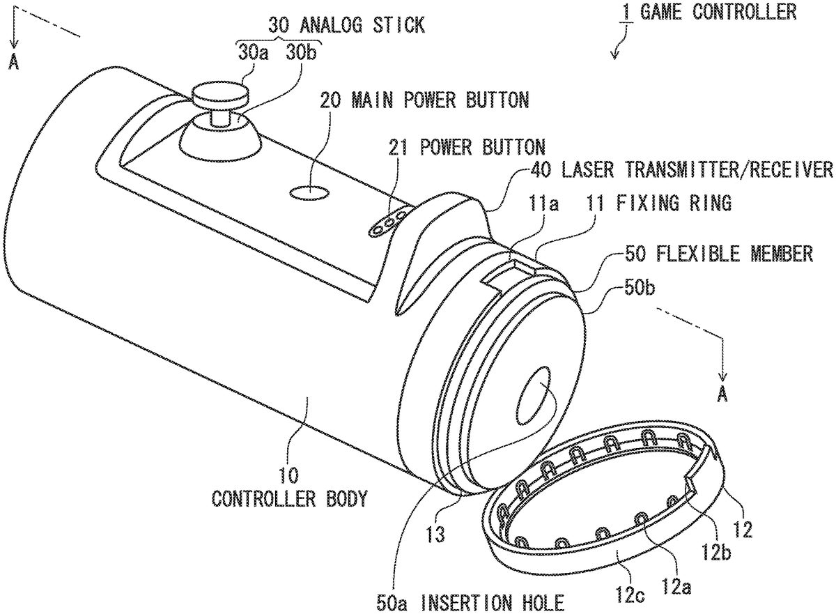
DESCRIPTION OF EMBODIMENTS An embodiment of the present invention shall now be described in detail with reference to the drawings. Embodiment FIG. 1is a perspective view of a game controller according to the embodiment of the present invention,FIG. 2Ais a side view thereof,FIG. 2Bis an upper view thereof, andFIG. 2Cis a front view thereof. In the following description, “wave” is a general term for sound waves, radio waves, and light. With the present embodiment, an example where, among “waves,” “light” (laser light) is used shall be described, and with a modification example, an example where a “sound wave” (ultrasonic wave) is used shall be described. The game controller1according to the present embodiment is for operating a game executed on a personal computer or a game machine. As shown inFIG. 1,FIG. 2A,FIG. 2BandFIG. 2C, the game controller1includes a controller body10to which is attached a flexible member50having formed therein an insertion hole50ainto which a length is inserted, a laser transmitter/receiver40(detection means) that is installed on an outer periphery of the controller body10and measures a distance with respect to a base surface of the length by transmission and reception of a wave to detect an insertion degree of the length inserted from the insertion hole50a, a control circuit45(output means) (seeFIG. 5andFIG. 6) that outputs the insertion degree of the length detected by the laser transmitter/receiver40, and rubber bands15(attaching member) (seeFIG. 3A,FIG. 3B,FIG. 4AandFIG. 4B) that enable a plurality of the flexible members50differing in outer dimensions to be attached detachably. The controller body10is normally formed of a plastic, such as polyethylene (PE), polypropylene (PP), polyvinyl acetate (PVA), acrylonitrile-butadiene-styrene copolymer (ABS), etc. With the game controller1, a game can also be operated in a state where the controller body10of cylindrical shape is gripped with one or both hands. A main power button20that turns power on ...
DESCRIPTION OF EMBODIMENTS
An embodiment of the present invention shall now be described in detail with reference to the drawings.
Embodiment
FIG. 1is a perspective view of a game controller according to the embodiment of the present invention,FIG. 2Ais a side view thereof,FIG. 2Bis an upper view thereof, andFIG. 2Cis a front view thereof.
In the following description, “wave” is a general term for sound waves, radio waves, and light. With the present embodiment, an example where, among “waves,” “light” (laser light) is used shall be described, and with a modification example, an example where a “sound wave” (ultrasonic wave) is used shall be described.
The game controller1according to the present embodiment is for operating a game executed on a personal computer or a game machine.
As shown inFIG. 1,FIG. 2A,FIG. 2BandFIG. 2C, the game controller1includes a controller body10to which is attached a flexible member50having formed therein an insertion hole50ainto which a length is inserted, a laser transmitter/receiver40(detection means) that is installed on an outer periphery of the controller body10and measures a distance with respect to a base surface of the length by transmission and reception of a wave to detect an insertion degree of the length inserted from the insertion hole50a, a control circuit45(output means) (seeFIG. 5andFIG. 6) that outputs the insertion degree of the length detected by the laser transmitter/receiver40, and rubber bands15(attaching member) (seeFIG. 3A,FIG. 3B,FIG. 4AandFIG. 4B) that enable a plurality of the flexible members50differing in outer dimensions to be attached detachably.
The controller body10is normally formed of a plastic, such as polyethylene (PE), polypropylene (PP), polyvinyl acetate (PVA), acrylonitrile-butadiene-styrene copolymer (ABS), etc.
With the game controller1, a game can also be operated in a state where the controller body10of cylindrical shape is gripped with one or both hands. A main power button20that turns power on and off, a power button21of the laser transmitter/receiver40, and an analog stick30constituted of an operating plate30aand a rod30bare installed on an outer surface of the controller body10. On and off are repeated when the main power button20is pressed. The power button21is turned on and off by sliding. Also, an LED (Light Emitting Diode), etc., that lights up in accordance with a progress state of the game can be provided as well.
FIG. 3AandFIG. 3Bare exploded perspective views of the game controller according the embodiment of the present invention,FIG. 4Ais a perspective view of a state where the flexible member50is removed from a cylindrical bottom portion10aof the controller body10, andFIG. 4Bis a perspective view of a state where the flexible member50is fixed to the cylindrical bottom portion10aof the controller body10.
As shown inFIG. 3A,FIG. 3B,FIG. 4AandFIG. 4B, the controller body10is of a cylindrical shape with bottom and includes a cylindrical bottom portion10a, a cover portion10bof semi-cylindrical shape that is mounted to an outer peripheral portion of a front side (insertion hole50aside) of the cylindrical bottom portion10a, a fixing ring11(seeFIG. 1) of circular annular shape that combines and fixes the front side of the cylindrical bottom portion10aand a front side of the cover portion10b, and a flexible member fixing ring12that is pivotably mounted via a hinge13to an outer peripheral portion of the fixing ring11and fixes the flexible member50by pressing it from peripheral directions.
As shown inFIG. 1, the fixing ring11has, on an outer peripheral portion at an upper surface side (laser transmitter/receiver40side), a recess11athat locks a hook12b(to be described below) of the flexible member fixing ring12. The flexible member fixing ring12has a main body ring portion12aabutting an inner peripheral surface against and thereby holding a small diameter portion50b(to be described below) of the flexible member50, the hook12bthat, when the flexible member is fixed, combines with the recess11aof the fixing ring11to lock the main body ring portion12a, and a plurality of projections12cthat are provided on the inner peripheral surface of the main body ring portion12aand press an outer peripheral portion of the flexible member50from the peripheral directions. By the plurality of projections12cpressing the outer peripheral portion of the flexible member50, the flexible member50is prevented from moving inadvertently in outer radial directions and front/rear directions.
The main body ring portion12aof the flexible member fixing ring12is mounted via the hinge13to an outer peripheral portion of a lower surface side of the fixing ring11. When the hook12bof the flexible member fixing ring12is removed from the recess11aof the fixing ring11, the main body ring portion12ais opened outward and the small diameter portion50bof the flexible member50is exposed as shown inFIG. 1. By turning the fixing ring11to a predetermined position in this state, the fixing ring11can be removed from the cylindrical bottom portion10aand the cover portion10b, and attachment/detachment of the flexible member50becomes enabled.
As shown inFIG. 3AandFIG. 3B, the cover portion10bhas a step portion10cat an end portion at a rear side (opposite side to the insertion hole50a) and the step portion10cis combined with a circumferential inner surface10dat a bottomed side of the cylindrical bottom portion10ato engage the rear side of the cover portion10b. Also, the cover portion10bhas a rib10eof semicircular shape at an end portion at a front side (insertion hole50aside) and the rib10eis combined with a rib10fof semicircular shape at an end portion at a front side (insertion hole50aside) of the cylindrical bottom portion10a. A circular opening portion10ghaving a step portion constituted of the rib10eand the rib10fis thereby formed at a front side (insertion hole50aside) of the controller body10, and the fixing ring11(seeFIG. 1) of circular annular shape can be fixed to outer peripheral portions of the rib10eand the rib10f.
At end surfaces at which the cylindrical bottom portion10aand the cover portion10bare combined, an engaging projection10hand an engaging groove10iengaging with the engaging projection10hare provided at the cover portion10band the cylindrical bottom portion10a, respectively, to enable both components to be engaged tightly.
In a state where the fixing ring11is combined with an outer peripheral surface of the circular opening portion10gof the cylindrical bottom portion10aand the cover portion10b, the cover portion10bwill not become detached and the flexible member50will not fall off from the controller body10even if vibration or impact of some degree is applied to the controller body10.
As shown inFIG. 3A,FIG. 3B,FIG. 4AandFIG. 4B, at an inner peripheral surface of the cylindrical bottom portion10a, a plurality of columns of the rubber bands15are provided at positions orthogonal to a direction of entry of the length. The rubber bands15are constituted of expandable/contractible elastic members and can securely fix front and rear portions of the flexible member50as shown inFIG. 4B. With the present invention, a sensor is not provided inside the controller body10and therefore a wide space can be provided inside the controller body10. Also, there is no dependence on sensor position and therefore a degree of freedom of design in the internal space is high. Due to these features, designing can be performed with material quality, shape, installation position, and installed quantity being optimal in regard to the attaching member that detachably attaches the flexible member50. The attaching member (the rubber bands15in the present case) can thereby be installed and, in particular, flexible members of different sizes can be fixed securely.
The flexible member50has the insertion hole50aenabling insertion of the length, and a small diameter portion50bprovided at an end portion at the insertion hole50aside and being for restriction, by the flexible member fixing ring12, of movement of the flexible member50in an axial direction.
As shown inFIG. 1andFIG. 4B, a large portion of the flexible member50is installed in an interior of the controller body10and a portion of the insertion hole50aof the flexible member50is in a state of being exposed to an exterior of the controller body10. Also, as shown inFIG. 4A, the flexible member50is attachable/detachable to and from the controller body10and the rubber bands15when the cover portion10bof the controller body10is opened.
The flexible member50suffices to have a flexibility of a degree such that a diameter of the insertion hole50ais pressingly expanded when a slender object that is thicker than the diameter of the insertion hole50ais inserted into the insertion hole50aand is formed of a material of high flexibility, such as an elastomer, etc. The insertion hole50aenabling insertion of a finger or other length is formed in a portion of the flexible member50exposed to the exterior of the controller body10.
FIG. 5is a sectional view taken along A-A ofFIG. 1. InFIG. 5, structures besides portions related to the laser transmitter/receiver40installed on the outer periphery of the controller body10are simplified.
As shown inFIG. 5, the laser transmitter/receiver40that measures the distance with respect to the base surface of the length by transmission and reception of the wave to detect the insertion degree of the length inserted from the insertion hole50ais disposed on the outer periphery of the controller body10. The laser transmitter/receiver40is connected via a wiring cable44(output means) to the control circuit45(output means) installed in the cylindrical bottom portion10aof the controller body10. The control circuit45supplies power to the laser transmitter/receiver40and receives a sensor signal from the laser transmitter/receiver40. The control circuit45outputs the insertion degree of the length detected by the laser transmitter/receiver40. Here, the laser transmitter/receiver40and the control circuit45are driven by an unillustrated battery.
The laser transmitter/receiver40includes, for example, a laser transmitting portion constituted of a laser diode and a light projecting lens and a laser receiving portion constituted of a light receiving lens and a CMOS (Complementary Metal Oxide Semiconductor) or other light receiving element, irradiates the laser light (see projected laser light a inFIG. 5) onto the base surface, and, by reflected light thereof (see received laser light b inFIG. 5), detects an entry distance of the length projecting from the base surface. The laser transmitter/receiver40may be of any ranging method as long as laser light is used. Representative distance measuring methods using laser include a “triangulation ranging method” and a “phase difference ranging method.” The “triangulation ranging method” is a method where reflected light of a laser irradiated onto an object is read by a light receiving element inside a sensor and distance measurement is performed using principles of triangulation. The “triangulation ranging method” has an advantage that the sensor is comparatively inexpensive, compact, and high in precision. Also, if the “phase difference ranging method” is used, detection of along distance is enabled.
Also, the base surface is a surface from which the length projects and may be of any arrangement as long as it is a surface that can reflect the laser light. For example, if the length is a finger, the base surface is a surface of the wrist or the body.
The game controller1has an arrangement where the laser transmitter/receiver40is installed at an exterior of the controller body10(on the outer periphery of the controller body10in the present case) and therefore, even though the insertion degree of the length into the flexible member50in the interior of the controller body10is detected, the insertion degree of the length into the flexible member50can be detected without dependence on an internal state (internal structure) of the controller body10.
As shown inFIG. 5, when a user inserts a finger or other length into the insertion hole50aof the flexible member50, a distance from the laser transmitter/receiver40installed on the outer periphery of the controller body10to the base surface (surface of the wrist or the body) changes. The laser transmitter/receiver40measures the distance from the laser transmitter/receiver40to the base surface by transmission and reception of the laser light to detect the insertion degree of the length inserted from the insertion hole50a. The laser transmitter/receiver40outputs the sensor signal to the control circuit45via the wiring cable44. The insertion degree of the length can thereby be detected in real time. By using the laser light as the wave, the laser transmitter/receiver40can make measurements noncontactingly and with high precision.
As described above, the game controller1of the present embodiment includes the controller body10to which is attached the flexible member50having formed therein the insertion hole50ainto which the length is inserted, the laser transmitter/receiver40that is installed on the outer periphery of the controller body10and measures the distance with respect to the base surface of the length by transmission and reception of the wave to detect the insertion degree of the length inserted from the insertion hole50a, and the wiring cable44and the control circuit45that output the insertion degree of the length detected by the laser transmitter/receiver40.
With the device described in PTL 1, a plurality of the internal input means had to be disposed to detect the insertion degree of the length (paragraph [0058] of PTL 1). On the other hand, with the present embodiment, the insertion degree of the length can be detected using one laser transmitter/receiver40even in a case of accommodating a game requiring a complex operation. That is, the insertion degree of the length can be detected without disposing a plurality of the detection means.
With the device described in PTL 1, a sensor is provided inside the controller body and therefore, there are restrictions in sensor position, size and shape of the flexible member, etc. On the other hand, the game controller1of the present embodiment is of the arrangement where the laser transmitter/receiver40is installed on the outer periphery of the controller body10and therefore, the insertion degree of the length into the flexible member50can be detected without dependence on the internal state of the controller body10. Flexible members50differing in size and shape can be disposed freely.
With the present embodiment, the controller body10has the attaching member (rubber bands15) that enables a plurality of the flexible members50differing in outer dimensions to be attached detachably. Conventionally, the internal input means functions by contact or pressing and therefore the flexible member is restricted to that of dedicated size even if it is detachable. With the present embodiment, a sensor is not provided inside the controller body10and therefore, the degree of freedom of design in the space inside the controller body10is high. Therefore, the material quality, shape, installation position, and installed quantity can be designed optimally in regard to the attaching member that detachably attaches the flexible member50and flexible members of different sizes can be fixed securely.
Modification Example
With the modification example, an example where, among “waves,” a “sound wave” (ultrasonic wave) is used shall be described.
FIG. 6is a sectional view of a game controller1A of the modification example. Components that are the same as those ofFIG. 5are provided with the same symbols and description of redundant parts shall be omitted.
As shown inFIG. 6, the game controller1A includes an ultrasonic sensor40A (detection means) in place of the laser transmitter/receiver40ofFIG. 1toFIG. 5.
The ultrasonic sensor40A emits an ultrasonic wave, receives the ultrasonic wave reflected upon hitting the base surface, and determines a distance to the base surface from a product of a speed (speed of sound) at which the ultrasonic wave is transmitted through air and half of a time of transmission and reception (propagation time).
Also, the ultrasonic sensor40A may use the Doppler effect to perform speed measurement with the ultrasonic wave and detect movement of insertion of the length.
According to the present modification example, the same effects as the embodiment can be exhibited, that is, the insertion degree of the length can be detected using one ultrasonic sensor40A and also, the flexible members50differing in size and shape can be disposed freely inside the controller body10.
Also, in general, an ultrasonic sensor can be incorporated at a lower cost than a laser transmitter/receiver.
The above description is illustrative of preferred embodiments of the present invention and the scope of the present invention is not restricted thereto.
For example, the game controllers1and1A of the present embodiment may have a USB (Universal Serial Bus) connector in assumption of being externally connected to a personal connector. Also, arrangement as a remote controller equipped with a wireless communication function by Bluetooth (registered trademark), etc., is allowable or being integrally connected by a connection cable to a game machine, etc., is allowable as well.
The disclosure of Japanese Patent Application No. 2019-097625 filed on May 24, 2019 including the description, claims and drawings is incorporated herein by reference in its entirety.
All publications, patents, and patent applications cited in this description are incorporated herein by reference in their entirety.
REFERENCE SIGNS LIST
1,1A Game controller10Controller body10aCylindrical bottom portion10bCover portion11Fixing ring15Rubber band (attaching member)20Main power button21Power button30Analog stick40Laser transmitter/receiver (detection means)40A Ultrasonic sensor (detection means)44Wiring cable (output means)45Control circuit (output means)50Flexible member50aInsertion hole
Claims
- A game controller comprising: a controller body to which is attached a flexible member having formed therein an insertion hole into which a length is inserted;a detection means configured to be installed on an outer periphery of the controller body and measure a distance with respect to a base surface of the length by transmission and reception of a wave to detect an insertion degree of the length inserted from the insertion hole, the detection means being further configured to be installed on an outer periphery of the controller body away from the insertion hole through which the length is inserted;and an output means configured to output the insertion degree of the length detected by the detection means, wherein the controller body has an attaching member that enables a plurality of flexible members differing in outer dimensions to be attached detachably.
- The game controller according to claim 1 , wherein the wave is laser light.
Disclaimer: Data collected from the USPTO and may be malformed, incomplete, and/or otherwise inaccurate.