U.S. Pat. No. 11,298,617
GAME PROGRAM, GAME PROCESSING METHOD, AND INFORMATION PROCESSING DEVICE
AssigneeKOEI TECMO GAMES CO., LTD.
Issue DateNovember 13, 2020
Illustrative Figure
Abstract
A non-transitory computer-readable recording medium having computer-readable instructions stored thereon, which when executed, causes a computer to execute a process of a game program, is provided. The process includes a step (a) of setting a default position of a virtual camera; a step (b) of calculating an outer edge of multiple objects arranged in a given region in the virtual space; a step (c) of determining a target position in an interior of the outer edge, to which the virtual camera is directed; a step (d) of adjusting a height of the virtual camera at the default position so as to display all of the plurality of objects in the region when the virtual camera is directed from the default position to the target position; and a step (e) of operating the virtual camera to be directed to the target position from the adjusted height of the default position.
Description
DETAILED DESCRIPTION OF THE EMBODIMENTS In the following, embodiments for carrying out the present disclosure will be described. Note that in the specification and the drawings, the same reference symbols are assigned to substantially the same elements, to omit duplicate descriptions. According to the present disclosure, it is possible to provide a medium of a game program, a game processing method, and an information processing device that are capable of looking over and displaying a game. Game System FIG. 1is a diagram illustrating a configuration of a game system1according to the embodiment. The game system1of the embodiment provides various services related to games to players via a network N (e.g., the Internet). The game system1includes a server10and multiple terminal devices30. The server10is an example of an information processing device that provides various game-related services to multiple terminal devices30. The server10may be a personal computer, a workstation, a cloud computer, or the like. The terminal device30is an example of an information processing device used by a player when playing a game. The terminal device30may be a smartphone, a personal computer, a portable game device, a game controller, a tablet computer, a wearable computer, or a game device for business use. The terminal device30requests the server10to distribute various items of information related to games (game programs, game screens, etc.). In response to receiving a request for distribution of various items of information from the terminal device30, the server10distributes a game program or a web page of a game screen to be played on the terminal device30. The terminal device30has a function of a web browser that allows a player to browse a web page displaying a game screen. By this function, the terminal device30can display a web page such as a game screen distributed from the server10. Note that the number of ...
DETAILED DESCRIPTION OF THE EMBODIMENTS
In the following, embodiments for carrying out the present disclosure will be described. Note that in the specification and the drawings, the same reference symbols are assigned to substantially the same elements, to omit duplicate descriptions.
According to the present disclosure, it is possible to provide a medium of a game program, a game processing method, and an information processing device that are capable of looking over and displaying a game.
Game System
FIG. 1is a diagram illustrating a configuration of a game system1according to the embodiment. The game system1of the embodiment provides various services related to games to players via a network N (e.g., the Internet). The game system1includes a server10and multiple terminal devices30. The server10is an example of an information processing device that provides various game-related services to multiple terminal devices30. The server10may be a personal computer, a workstation, a cloud computer, or the like.
The terminal device30is an example of an information processing device used by a player when playing a game. The terminal device30may be a smartphone, a personal computer, a portable game device, a game controller, a tablet computer, a wearable computer, or a game device for business use.
The terminal device30requests the server10to distribute various items of information related to games (game programs, game screens, etc.). In response to receiving a request for distribution of various items of information from the terminal device30, the server10distributes a game program or a web page of a game screen to be played on the terminal device30.
The terminal device30has a function of a web browser that allows a player to browse a web page displaying a game screen. By this function, the terminal device30can display a web page such as a game screen distributed from the server10.
Note that the number of terminal devices30connected to the game system1is not limited to three, and may be one, or greater than or equal to two. Multiple servers may interoperate with each other to implement the functions of the server10. The server10may provide an on-line game in which multiple terminal devices30connected to the network N are divided into friends and enemies to fight against each other. However, the server10is not limited as such, and can provide all types of games including sports games such as basketball and tennis games, racing games, town planning games, and the like. The server10can provide a function by which a user other than the player can watch these games. The terminal devices30may include a terminal device30on which a player is playing a game, and a terminal device30on which a user other than the player is watching the game. On the latter terminal device30, the user can watch the circumstances of a battle game, a match of a sports game, and the like. In particular, the server10operates a virtual camera so that it is possible to look over and display the entire game; therefore, the user can watch the game dynamically and grasp the entire game easily.
Hardware Configuration of Server10
Next, the hardware configuration of the server10will be described with reference toFIG. 2.FIG. 2is a diagram illustrating the hardware configuration of the server10according to the embodiment. The server10includes a CPU (Central Processing Unit)131, a memory132, and a communication device133. The CPU131controls the server10. The memory132is, for example, a storage device such as a memory in the server10, which is directly accessible by the CPU131. The communication device133is a communication device such as a network card to control communication.
In the server10, various types of microprocessors such as a GPU (Graphics Processing Unit) and a DSP (Digital Signal Processor), and various types of memories such as a VRAM, a RAM, and a ROM may be installed.
The server10includes game management functions of providing to the terminal device30various game data items necessary for playing a game using the terminal device30through arithmetic processing, and of controlling and managing execution of game processing executed on the terminal device30. The server10causes the CPU131to execute arithmetic processing based on predetermined programs and data, to execute game processing of a battle game and operations of the virtual camera. Note that the processing implemented on the server10are not limited to these, and may be added or omitted as appropriate.
Hardware Configuration of Terminal Device30
Next, the hardware configuration of the terminal device30will be described with reference toFIG. 3.FIG. 3is a diagram illustrating a hardware configuration of the terminal device30according to the embodiment. The terminal device30includes a CPU121, a memory122, a communication device123, an input device124, and a display device125. The CPU121controls the terminal device30. The memory122is, for example, a storage medium such as a memory in the terminal device30, which is directly accessible by the CPU121. The communication device123is a communication device such as a network circuit to control communication. The input device124is an input device such as a camera or a touch panel. The display device125is an output device such as a display.
The terminal device30executes a game provided from the server10. In one example of the embodiment, the player uses the terminal device30to play a battle game provided from the server10, in which three to three characters as friends and enemies fight against each other on a stage formed like a miniature garden. At this time, the server10provides a mechanism for operating a virtual camera so as to display all characters on the stage automatically. However, the game played by the player is not limited to a battle game, and any game such as a role-playing game (RPG) may be played.
Functional Configuration of Server10
Next, the functional configuration of the server10will be described with reference toFIG. 4.FIG. 4is a diagram illustrating the functional configuration of the server10according to the embodiment. The server10includes a control unit11, a storage unit12, and a communication unit13.
The control unit11transmits and receives data between the units, and controls the entire server10. The control unit11is implemented by the CPU131executing a program stored in a predetermined area in the memory132.
The storage unit12stores game programs, various types of data items, and various types of tables for executing battle games and watching processes. The storage unit12is implemented by, for example, the memory132. The storage unit12includes a ROM (read-only memory) that is read-only to store game programs, and a RAM (random access memory) that is rewritable to be used as a work area for calculation processes by the control unit11. The storage unit12may also be implemented by a non-volatile storage device, for example, a flash memory, a hard disk, or the like.
The communication unit13includes a function of communicating with the terminal device30and the other devices. The communication unit13includes a function as a receiver for receiving various items of data transmitted from the terminal device30, and a function as a transmitter for transmitting various items of data to the terminal device30in response to a command from the control unit11. The communication unit13is implemented by, for example, a NIC (Network Interface Card).
The control unit11includes a game execution processing unit14, a setting unit15, a determination unit16, an arithmetic unit17, an adjustment unit18, a camera operation unit19, and a display unit20. The game execution processing unit14includes a function of executing processes related to battle games. In one example of the embodiment, the game execution processing unit14executes a process of determining win or lose for a three-to-three battle (fight) between friend characters including a player character and enemy characters.
The setting unit15includes a function of setting a default position of the virtual camera. The setting unit15can set multiple default positions. The virtual camera is placed at one of the default positions. In one example of the embodiment, the setting unit15sets four corners of a stage as the default positions of the virtual camera, and further sets two positions inside the stage as the default positions. The virtual camera captures images of an ongoing game on the stage in a virtual space from the default position. The virtual camera can be moved from one default position among the multiple default positions to another.
The determination unit16includes a function of calculating an outer edge of multiple objects arranged in a given region in the virtual space. The given region may be the entirety or part of a field where the game is played. In an example of the embodiment, the given region may be the entirety or part of a stage where the game is played. The given region may be a region among partitioned regions of the field where the game is played that satisfies a desired condition.
The arithmetic unit17includes a function of calculating the distance between two characters. In a three-to-three battle game of a miniature garden type provided from the server10, three friend characters and three enemy characters are displayed on the stage. In one example of the embodiment, the arithmetic unit17calculates the distances between every pair among the six characters, to calculate the distance between the farthest characters. The arithmetic unit17repeatedly executes this calculation at predetermined time intervals, to calculate the distance between the farthest characters at that time, depending on moves of the respective characters. Note that although the arithmetic unit17executes the calculation for the six characters, the number of characters subject to the calculation is not limited to six. Also, the objects subject to the calculation is not limited to characters, and the object may be a building, a tree, and the like.
The determination unit16determines a target position to which the virtual camera is directed, based on the distance between the farthest characters calculated by the arithmetic unit17.
The adjustment unit18includes a function of adjusting the height of the virtual camera at a default position, so as to display all characters on the stage when the virtual camera is directed to the target position from the default position.
The camera operation unit19includes a function of operating the virtual camera to be directed to the target position from the adjusted height of the default position. The camera operation unit19may change the position where the virtual camera is placed from one default position to another default position while directing the virtual camera to follow the changing target position.
The display unit20controls a web page of a game screen of images presenting the circumstances of a game on the stage captured by the virtual camera. The web page of the game screen controlled by the display control unit20is transmitted to the terminal device30through the communication unit13, to be displayed on the display unit35of the terminal device30.
The storage unit12stores a camera default position information table21and an object information table22.
Camera Default Position Information Table
The camera default position information table21stores the default positions to place the virtual camera.FIG. 5is a diagram illustrating an example of the camera default position information table21according to the embodiment. In the camera default position information table21, sequential numbers are assigned to the default positions of the virtual camera, and the coordinates (x, y, z) are specified for each default position having the corresponding number. In the example inFIG. 5, there are six default positions numbered 1 to 6 for the virtual camera, and each default position is specified by the coordinates (see the positions 1 to 6 inFIGS. 9A-9B). The x and y coordinates are coordinates on the stage in the horizontal direction, and the z coordinate is a coordinate on the stage in the vertical direction. In the camera default position information table21, the initial value of the z coordinate of each default position is set to z1, and the height is the same for all the default positions in the initial state. However, in the camera default position information table21, the initial values of the z coordinate of the default positions may be set to different heights.
Object Information Table
The object information table22stores a given region to serve as an imaging region in the virtual space, and an object to be imaged.FIG. 6is a diagram illustrating an example of the object information table22according to the embodiment. In the example inFIG. 6, in the object information table22, the region is set to a region determined by coordinates (x1, y1, z1) of the upper left default position 1 and the coordinates (x2, y2, z1) of the lower right default position 3, and characters C1to C6are stored as the objects in the region. Note that as the region stored in the object information table22, the entirety or part of the field may be set. Also, objects in the region may be other than characters.
Functional Configuration of Terminal Device30
Next, the functional configuration of the terminal device30will be described with reference toFIG. 7.FIG. 7is a diagram illustrating an example of the functional configuration of the terminal device30according to the embodiment. The terminal device30includes a control unit31, a storage unit32, a communication unit33, an input unit34, and a display unit35.
The control unit31transmits and receives data between the units, and controls the entire terminal device30. The control unit31is implemented by the CPU121executing a program stored in a predetermined area in the memory122.
The storage unit32is connected to the control unit31via a bus, to execute processes of referring to, reading, and rewriting stored data, in response to a command from the control unit31. The storage unit32may also be implemented by, for example, a flash memory, a hard disk, or the like.
The communication unit33communicates with the server10through the network N. The communication unit33includes a function as a receiver for receiving various items of data transmitted from the server10, and a function as a transmitter for transmitting various items of data to the server10in response to a command from the control unit31. The communication unit13is implemented by, for example, a NIC (Network Interface Card).
The input unit34is used by the player to perform various operations (such as game operations), and implemented by, for example, operation buttons, a touch panel, and the like. The display unit35is provided for displaying a game screen in response to a command from the control unit31, and implemented by, for example, a liquid crystal display (LCD). The display unit35displays a web page of a game screen generated by the server10and received by the communication unit33, on the screen of the terminal device30.
Operations of Battle Game and Virtual Camera
Next, a battle game provided by the game system1will be outlined briefly. The game system1provides an on-line game in which a battle game is played with multiple terminal devices30connected to the server10, separated as enemies and friends.
In the game system1, a player owns one character (player character) and can play the battle game using the player character owned by himself/herself. The game execution processing unit14determines the enemy characters as the opponent of the player character and the friend characters who support the player character, and based on parameters (the physical strength, offensive power, and defensive power) set for each character, determines the winners and the losers of the battle between these characters. In the case of winning the battle against the enemy characters, items owned by the enemy characters and/or the enemy characters themselves are given to the player.
A user other than the player can display the entire battle game on the terminal device30of the user, to watch the game. In this way, the user can look over moves of enemy characters present outside the surroundings of the player character, to watch the game. In this way, it is easy to grasp the entire game. Also, it is possible to display the entire battle game on the terminal device30, which functions as a map.
First Embodiment
In the following, operations of the virtual camera according to a first embodiment executed during the game processing of a battle game will be described with reference toFIGS. 8 to 10.FIG. 8is a flow chart illustrating camera operations according to a first embodiment.FIGS. 9A-9Bare diagrams illustrating camera operations according to the first embodiment.FIGS. 10A-10Bare diagrams illustrating an example of a method of determining the outer edge of multiple objects on a stage according to the embodiment.
In response to a request for distribution of various items of information related to a battle game (a game program, a game screen, etc.) from the terminal device30to the server10, the server10starts providing the game contents to the terminal device30. The process illustrated inFIG. 8is started when the game execution processing unit14executes the battle game at this timing.
First, at Step S1, the setting unit15sets a given region in the virtual space. In one example of the embodiment, a stage S is set as the given region in the virtual space, and the region to be set may be the entirety or part of a field where the battle game is played. The region to be set may be set automatically, or may be set as a region selected by the player or a user other than the player.
Next, at Step S2, the setting unit15sets default positions of the virtual camera based on the camera default position information table21(step (a)). In one example of the embodiment, as illustrated inFIGS. 9A and 9B, the setting unit15sets the default positions 1 to 4 of the virtual camera at the four corners of the box-shaped stage S, and sets the default positions 5 and 6 of the virtual camera inside the stage S. The coordinates of the default positions 1 to 6 are as listed inFIG. 5as the coordinates of the default positions 1 to 6. However, the number of default positions of the virtual camera may be one, or greater than or equal to two.
Next, at Step S3inFIG. 8, the determination unit16determines target objects based on the object information table22. In one example of the embodiment, the determination unit16determines characters C1to C6arranged in the region on the stage S as the target objects, based on the object information table22illustrated inFIG. 6.
Next, at Step S4, the arithmetic unit17calculates the outer edge of the characters C1to C6(step (b)). From the calculated outer edge, at Step S5, the determination unit16determines a target position to be used when capturing an image by the virtual camera (step (c)). For example, the arithmetic unit17calculates the distance for each pair among the characters C1to C6, to calculate the farthest distance among the calculated distances among the characters. Then, the determination unit16determines the center point of the farthest distance among the calculated distances among the characters, as the target position.
At this time, as illustrated inFIG. 10A, as the outer edge of the characters C1to C6, a circle A whose diameter is a distance (a straight line) between the character C1and the character C4, which is the farthest distance among the calculated distances among the characters, is identified. Therefore, the center of the circle A is determined as the target position P1to which the virtual camera is to be directed. Then, at Step S6, the determination unit16determines a default position of the virtual camera based on the determined target position P1.
The determination unit16may determine a default position, for example, that is closest to the determined target position P1and satisfies a specific condition, as the default position of the virtual camera. In the example inFIG. 9A, as the position that is closest to the target position P1located at the midpoint between the character C1and the character C4, and satisfies a specific condition, the default position 5 is determined as the default position of the virtual camera D. However, a default position that satisfies a specific condition for the determined target position P1may be determined as the default position of the virtual camera.
As examples of the specific condition, a predetermined distance condition; a point located at a certain height or higher or at a certain height or lower; a point around which the density of player characters is low; and a point around which there is no obstacle, may be listed. The specific condition may be one of these conditions or a combination of two or more.
Next, at Step S7inFIG. 8, the adjustment unit18adjusts the z coordinate (height) of the virtual camera at the default position, so as to display all of the target objects when the virtual camera is directed from the default position to the target position (step (d)). For example, in the case where not all of the target objects are displayed at the height of the initial value z1 of the z coordinate, the adjustment unit18raises the z coordinate to place the virtual camera at a position higher than the initial value.
For example, in the example inFIG. 9A, the adjustment unit18raises the z coordinate at the default position 5 from the initial value z1 to z2 to place the virtual camera D at a higher position at the default position 5, so as to capture images toward the target position P1, to an extent that the most distant characters C1and C4are displayed. In this way, it is possible to look over all of the characters C1to C6and to display them as a whole.
After that, as illustrated inFIG. 9B, as the characters C1to C6move on the stage S, the adjustment unit18calculates again the distance between each pair among the characters C1to C6. As a result, in the example inFIG. 9B, the distance between the character C2and the character C4is determined as the farthest, and the midpoint between the character C2and the character C4is determined as the latest target position P2. Also, the default position 5 that is closest to the target position P2and satisfies the specific condition, is determined as the default position of the virtual camera D.
In the case where all of the target objects are displayed at the initial value z1, the arithmetic unit17lowers the z-coordinate to a position at which all of the target objects are displayed and the target objects are displayed to be the largest, to place the virtual camera at a position lower than the initial value.
For example, inFIG. 9B, the adjustment unit18lowers the z coordinate at the default position 5 from the initial value z1 to z3 to an extent that the most distant characters C2and C4are displayed, to place the virtual camera D at a lower position at the default position 5, and to capture images toward the target position P2. In this way, it is possible to look over all of the characters C1to C6and to display them as a whole while making them displayed larger.
Next, at Step S8inFIG. 8, the camera operation unit19operates the virtual camera to be directed to the target position from the adjusted height of the default position (step (e)). Next, at Step S9, the display unit20generates a web page of the game screen on which all of the target objects are displayed, and display the web page on the terminal device30. In this way, as illustrated inFIGS. 9A and 9B, the virtual camera D can display an image in which all of the characters C1to C6as the target objects on the stage S, are looked over from above, on the terminal device30of the user. Thus, the user can grasp the movement of the entire game when watching the battle game.
Next, at Step S10, the control unit11determines whether a command of the end of the game or the mode switching is received. If it is determined that a command of the end of the game or the mode switching is received, the control unit11ends the current process. If it is determined that a command of the end of the game or the mode switching is not received, the control unit11returns to Step S4to repeat the processing at Steps S4to S9.
Note that the mode can be switched between three modes, which are a first-person viewpoint mode of showing the player character operated by the player; a third-person viewpoint mode of showing the surroundings of the player character; and a looking-over mode of looking over the entire game. The looking-over mode is a display mode in which all of the characters C1to C6on the stage S are displayed, and the movement on the stage S can be grasped as a whole, as will be described in an example.
Note that the first-person viewpoint mode is a display mode in which the viewpoint of the virtual camera is the same as that of the player who is playing the game. The third-person viewpoint mode is a display mode in which the viewpoint of the virtual camera is located at a certain distance away from the player character, to show the surroundings of the player character. The mode switching can be operated by the player or a user other than the player.
As described above, according to the operations of the virtual camera in the first embodiment, by looking over the game to display it as a whole, it becomes easier for the user to watch the battle game dynamically, and to grasp all moves of the target characters. Also, moves of the individual target characters change the distances among the target characters all the time. Therefore, control is repeated to calculate the distances among the target characters at predetermined time intervals to determine the midpoint between the farthest two characters as the target position, so as to determine the default position based on the target position, and to move the virtual camera by switching its position among the multiple default positions. In this way, the user can dynamically watch moves of all the characters on the stage S without performing any operation.
Second Embodiment
In the following, operations of the virtual camera according to a second embodiment executed during the game processing of a battle game will be described with reference toFIGS. 11 and 12.FIG. 11is a flow chart illustrating camera operations according to the second embodiment.FIGS. 12A-12Bare diagrams illustrating camera operations according to the second embodiment. In the process illustrated inFIG. 11, the steps executing the same as in the game processing illustrated inFIG. 8are assigned the same step numbers, to omit or simplify the description of these steps assigned the same step numbers.
For example, the processing at Step S1to Step S7is the same as that at Step S1to Step S7inFIG. 8according to the first embodiment; therefore, the description of these steps are omitted here. In the second embodiment, after processing Steps S1to S7, at Step S11, the camera operation unit19determines whether the virtual camera has moved from the preceding default position. If it is determined that the virtual camera has not moved from the preceding default position or there is no preceding default position (i.e., the initial operation of the virtual camera), the camera operation unit19proceeds to Step S8to operate the virtual camera from the default position at the adjusted height toward the target position (step (e)). Next, at Step S9, the display unit20generates a web page of the game screen on which all of the target objects are displayed, and display the web page on the terminal device30. Next, at Step S10, the control unit11determines whether a command of the end of the game or the mode switching is received. If it is determined that a command of the end of the game or the mode switching is received, the control unit11ends the current process. If it is determined that a command of the end of the game or the mode switching is not received, the control unit11stores the preceding default position at Step S13, returns to Step S4, and repeats the processing at Steps S4to S7, Step S11, Step S12, Steps S8to S10, and Step S13.
On the other hand, if it is determined at Step S11that the virtual camera has moved from the preceding default position, at Step S12, the camera operation unit19moves the virtual camera from the preceding default position to the next new default position, while directing the virtual camera to the target position so as to follow the changing target position. Next, the processing at Step S9and Step S10is executed. If it is determined that a command of the end of the game or the mode switching is received, the control unit11ends the current process.
As described above, according to the game processing including the operations of the virtual camera according to the second embodiment, by looking over the game to display it as a whole, it becomes easier for the user to watch the battle game dynamically. Also, moves of the individual target characters change the distances among the target characters all the time. Therefore, control is repeated to calculate the distances among the target characters at predetermined time intervals to determine the midpoint between the farthest two characters as the target position, so as to determine the default position based on the target position. Then, while directing the virtual camera to the target position so as to follow the changing target position, the virtual camera is moved from the preceding default position to the newly determined default position. In this way, when the default position to place the virtual camera changes, the virtual camera moves smoothly while watching the target position, and thereby, it is possible to move the virtual camera more smoothly, and the user can watch the battle game more dynamically. Note that the moving speed of the virtual camera may be constant or variable.
In the example inFIG. 12A, the virtual camera D in a state of being placed at the coordinates (x2, y1, z4) of the default position 4, is directed to the target position P3to capture images on the stage so as to display all of the characters C1to C6.
Next, by repeating Steps S4to S7, the target position and the default position that is closest to the target position and satisfies the specific condition are determined. In this case, while directing the virtual camera to the target position so as to follow the changing target position, the camera operation unit19moves from the preceding default position to the next new default position. At this time, suppose the characters have moved to change to the state fromFIG. 12AtoFIG. 12B. The camera operation unit19moves the virtual camera D from the preceding default position 4 to the newly determined default position 5, while directing the virtual camera D in the direction in which the target position changes from P3to P4so as to follow the change in target position P3to P4. In the example inFIG. 12B, moves the virtual camera D rom the default position 4 to the default position 5 while controlling the direction of the virtual camera D to follow a trajectory T that changes from the target position P3to the target position P4.
As described above, according to the operations of the virtual camera according to the second embodiment, by looking over the game to display it as a whole, it becomes easier for the user to watch the battle game dynamically, and to grasp all moves of the target characters. Also, by moving the virtual camera smoothly from the preceding default position to the next default position while directing the virtual camera to the target position so as to follow the change in the target position, it is possible to display realistic actions of the characters on the stage S, and to enjoy game watching.
In the first and second embodiments, at Step S6, although the default position is determined to be closest to the target position and to satisfy the specific condition so as to place the virtual camera at the determined default position, it is not limited as such. Depending on the distances between the target position and multiple default positions, a default position that is second, third, or fourth closest to the target position may be determined to place the virtual camera at this determined default position.
The game programs, game processing methods and information processing devices according to the embodiments disclosed in the present specification should be considered exemplary in all respects and not restrictive. The embodiments described above can be modified and improved in various forms without departing from the scope and gist of the appended claims. The matters described in the above embodiments may have other configurations within a consistent range, and may be combined within a consistent range.
For example, the method of calculating the outer edge of multiple objects placed on the stage is not limited to the method of setting as the outer edge a circle A that has a diameter being a line segment connecting the farthest two objects as illustrated inFIG. 10A. For example, as illustrated inFIG. 10B, among multiple objects, a polygon B connecting some of the objects positioned relatively outward may be set as the outer edge, to set the target position P1as the center of gravity of the polygon B, or the intersection point of lines connecting the vertices of the polygon B.
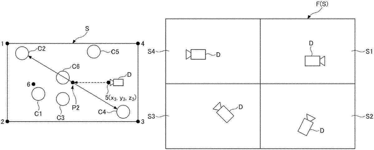
Also, as illustrated inFIG. 13, the entire field F in which the game is played may be set as the stage S in the virtual space, or part of the field F (S1to S4) may be set as the stage S in the virtual space.
Also, the stage S in the virtual space may be a region among partitioned regions (S1to S4) of the field F where the game is played, that satisfies a desired condition. For example, in the case where there are a number of characters in the field F (e.g., 50 friend characters, 50 enemy characters, etc.), the field may be divided into regions (S1to S4) to place a virtual camera D in each of regions, and in a region where a desired condition is satisfied, operations of the virtual camera D placed in the region may be executed according to one of the embodiments. As an example of the desired condition, the number of characters present in the region becoming less than or equal to a predetermined number (e.g., 20).
Also, the operations by the virtual camera according to the embodiment can also be used for displaying a map in a game other than battle games. For example, in a map of a city planning game, the operations of the virtual camera may be controlled so as to display all building objects.
All examples and conditional language recited herein are intended for pedagogical purposes to aid the reader in understanding the present inventive concept contributed by the inventor to furthering the art, and are to be construed as being without limitation to such specifically recited examples and conditions, nor does the organization of such examples in the specification relate to a showing of the superiority and inferiority of the present inventive concept. Although the embodiments of the present invention have been described in detail, it should be understood that the various changes, substitutions, and alterations could be made hereto without departing from the spirit and scope of the present inventive concept.
Claims
- A non-transitory computer-readable recording medium having computer-readable instructions stored thereon, which when executed, causes a computer to execute a process of a game program, the process comprising: setting a default position of a virtual camera;calculating an outer edge of a plurality of objects arranged in a given region in the virtual space;determining a target position in an interior of the outer edge, to which the virtual camera is directed;adjusting a height of the virtual camera at the default position so as to display all of the plurality of objects in the region when the virtual camera is directed from the default position to the target position;and operating the virtual camera to be directed to the target position from the adjusted height of the default position, wherein the calculating sets, as the outer edge, a circle having a diameter formed by a distance between two objects at a farthest distance among the plurality of objects, or a polygon that connects some of the plurality of objects positioned outward among the plurality of objects, and wherein the determining sets a center of the circle, a center of gravity of the polygon, or an intersection point of lines connecting vertices of the polygon, as the target position.
- The non-transitory computer-readable recording medium as claimed in claim 1 , repeating the calculating, the determining, the adjusting, and the operating.
- The non-transitory computer-readable recording medium as claimed in claim 2 , wherein the setting sets default positions of a plurality of virtual cameras, and wherein the operating changes the position where the virtual camera is placed from one default position to another default position while directing the virtual camera to follow the changing target position.
- The non-transitory computer-readable recording medium as claimed in claim 3 , wherein the operating changes a position at which the virtual camera is placed from one of the default positions to another of the default positions, depending on distances between the target position and default positions of the plurality of virtual cameras.
- The non-transitory computer-readable recording medium as claimed in claim 2 , wherein the operating moves the virtual camera while directing the virtual camera in a changing direction of the target position.
- The non-transitory computer-readable recording medium as claimed in claim 1 , wherein the given region in the virtual space is entirety or part of a field where the game is played.
- The non-transitory computer-readable recording medium as claimed in claim 1 , wherein the given region in the virtual space is a region among partitioned regions of a field where the game is played that satisfies a desired condition.
- A game processing method executed by a computer, the method comprising: setting a default position of a virtual camera;calculating an outer edge of the plurality of objects arranged in a given region in the virtual space;determining a target position in an interior of the outer edge, to which the virtual camera is directed;adjusting a height of the virtual camera at the default position so as to display all of the plurality of objects in the region when the virtual camera is directed from the default position to the target position;and operating the virtual camera to be directed to the target position from the adjusted height of the default position, wherein the calculating sets, as the outer edge, a circle having a diameter formed by a distance between two objects at a farthest distance among the plurality of objects, or a polygon that connects some of the plurality of objects positioned outward among the plurality of objects, and wherein the determining sets a center of the circle, a center of gravity of the polygon, or an intersection point of lines connecting vertices of the polygon, as the target position.
- An information processing device comprising: a memory;and a processor configured to execute: setting a default position of a virtual camera;calculating an outer edge of the plurality of objects arranged in a given region in the virtual space;determining a target position in an interior of the outer edge, to which the virtual camera is directed;adjusting a height of the virtual camera at the default position so as to display all of the plurality of objects in the region when the virtual camera is directed from the default position to the target position;and operating the virtual camera to be directed to the target position from the adjusted height of the default position, wherein the calculating sets, as the outer edge, a circle having a diameter formed by a distance between two objects at a farthest distance among the plurality of objects, or a polygon that connects some of the plurality of objects positioned outward among the plurality of objects, and wherein the determining sets a center of the circle, a center of gravity of the polygon, or an intersection point of lines connecting vertices of the polygon, as the target position.
Disclaimer: Data collected from the USPTO and may be malformed, incomplete, and/or otherwise inaccurate.