U.S. Pat. No. 11,298,610
ADJUSTABLE TRIGGER-STOPS FOR VIDEOGAME CONTROLLERS
AssigneePerformance Designed Products LLC
Issue DateJune 23, 2020
Illustrative Figure
Abstract
A video game controller has triggers that can be depressed by a user. The triggers have associated trigger stops actuatable to limit the travel of the trigger when depressed by the user. The trigger stop can be selectively operated by the user to vary the trigger stop location, and therefore the amount of travel of the trigger when depressed, between multiple (e.g., more than 2, more than 3, more than 4, 5, etc.) positions.
Description
DETAILED DESCRIPTION The present disclosure is directed toward adjustable trigger-stops and systems and methods for altering or enhancing videogame controller performance. A mechanical trigger-stop can be actuated via an actuator accessible to a user on the exterior of controller (e.g., moving a lever, a pin, a post, a slider, a knob, etc., touching a capacitive or other touch-sensitive switch, applying pressure to a squeeze switch, etc.). Adjusting a trigger-stop position can adjust a trigger-stop operating mode of the video game controller. For example, adjustment of the trigger-stop mechanism to one position can actuate a switching mechanism (e.g., a switch, relay, electronic signal, etc.) of the video game controller to effect a different mapping scheme/profile of electrical output signals communicated from the controller to the console from the mapping scheme/profile provided at a different position of the trigger-stop mechanism. Therefore, actuation of the trigger stop mechanism between different positions to alter the amount the trigger needs to be pulled before being stop (e.g., travel span distance between an undepressed condition to a fully depressed condition for the trigger), to afford quicker response times for the trigger during video game use, modifies the mapping scheme/profile of electrical signals generated by the controller and communicated to the video game console to activate the relevant functionality in the video game despite the different path along which the trigger may move on account of the trigger-stop position having been changed. FIG. 1illustrates a top perspective view of a videogame controller100in which the smart trigger-stop mechanisms described herein can be implemented. The videogame controller100can include a housing150with handles151that may be held by a user. The videogame controller100can include one or more control inputs, such as one or more buttons (e.g., buttons191,194), one or more joysticks (e.g., joysticks192,196), one or more directional pads (e.g., directional pad195), one ...
DETAILED DESCRIPTION
The present disclosure is directed toward adjustable trigger-stops and systems and methods for altering or enhancing videogame controller performance. A mechanical trigger-stop can be actuated via an actuator accessible to a user on the exterior of controller (e.g., moving a lever, a pin, a post, a slider, a knob, etc., touching a capacitive or other touch-sensitive switch, applying pressure to a squeeze switch, etc.). Adjusting a trigger-stop position can adjust a trigger-stop operating mode of the video game controller. For example, adjustment of the trigger-stop mechanism to one position can actuate a switching mechanism (e.g., a switch, relay, electronic signal, etc.) of the video game controller to effect a different mapping scheme/profile of electrical output signals communicated from the controller to the console from the mapping scheme/profile provided at a different position of the trigger-stop mechanism. Therefore, actuation of the trigger stop mechanism between different positions to alter the amount the trigger needs to be pulled before being stop (e.g., travel span distance between an undepressed condition to a fully depressed condition for the trigger), to afford quicker response times for the trigger during video game use, modifies the mapping scheme/profile of electrical signals generated by the controller and communicated to the video game console to activate the relevant functionality in the video game despite the different path along which the trigger may move on account of the trigger-stop position having been changed.
FIG. 1illustrates a top perspective view of a videogame controller100in which the smart trigger-stop mechanisms described herein can be implemented. The videogame controller100can include a housing150with handles151that may be held by a user. The videogame controller100can include one or more control inputs, such as one or more buttons (e.g., buttons191,194), one or more joysticks (e.g., joysticks192,196), one or more directional pads (e.g., directional pad195), one or more bumpers (e.g., bumper190) and one or more triggers (e.g., left trigger110, right trigger112) that may be exposed or accessible through a top and/or forward face of housing150A and operated by a user with their fingers.FIG. 1shows the triggers110,112in an undepressed condition. One of more of these controls inputs (e.g., button(s), joystick(s), directional pad(s), and/or trigger(s)) can be operatively coupled (e.g., mechanically and/or electrically coupled) to one or more internal components housed within and carried by the housing100.
The triggers110,112can be mechanically coupled with the housing150via a hinge (e.g., a spring loaded hinge), and electrically coupled with an internal sensor that detects the movement of the triggers110,112and generates or affects one or more signal(s) corresponding to such movements (or actuate a sequence of steps that results in such signal(s) being generated (e.g., via a transducer) or affected (e.g., by a variable resistor)). The trigger110,112can be depressed or otherwise displaced to a certain degree/distance when pressed by a user, and then may spring back (e.g., via a spring loaded hinge) to its resting position (e.g., undepressed condition) when released. The path along which the trigger110,112(or a portion of trigger110) moves when pressed by a user (e.g., between an undepressed condition and a fully depressed condition) is referred to herein as the “travel path” or “path of travel” and the distance of the travel path is referred to herein as the maximum travel span or maximum travel distance.
The controller design defines the maximum travel distance the trigger110,112can be depressed or otherwise moved along the travel path before being stopped or blocked by another structure (e.g., blocked by a portion of the housing, or a structure coupled with the housing such as a guide component). As further discussed below, the videogame controller100can have a trigger-stop mechanism that operable to “stop” the movement of trigger110,112at more than one location to vary the maximum travel distance of the trigger110,112. The trigger-stop mechanism can be actuated via an actuator348(seeFIG. 3A) operatively coupled thereto that is accessible to a user from outside of the controller housing (e.g., via an opening152in the bottom face150B of the housing150). The actuator348can be a slider that is moved outwardly toward an outer lateral edge of the controller100. However, the actuator348can have other suitable form factors, such as a lever, a pin, a post, a knob, etc.
FIG. 2shows a partial view of the controller100with the top face150A of the housing150removed. The controller100can include electronics200and optionally include a rumble or vibration motor R for providing haptic feedback to the controller100. The controller100can also include an electrical switch350(e.g., a mini-detector micro switch). The electronics200can include a processor175, a memory180, a transmitter185, and/or a power source190, which can be mechanically and/or electrically coupled with one another and/or with the housing150, and can operate alone or together to facilitate one or more implementations of the trigger-stop technology disclosed herein. For simplicity, various electrical components of the electronics200illustrated are depicted symbolically using boxes (e.g., the processor175, memory180, etc.).
Various components of the controller100are excluded fromFIG. 2to better illustrate a trigger-stop assembly300associated with the trigger110. As best shown inFIG. 2A, the trigger110can be rotatably coupled to the housing150via a spring-loaded hinge assembly. The spring-loaded hinge assembly can include a pin116and barrel114configuration, with a resilient or compliant member115(e.g., a spring, such as a torsion spring) applying a force between housing150and trigger110that imposes a resistance to trigger depressions. Though not specifically depicted, spring-loaded hinge assembly can include another barrel or sleeve member that is coupled to the housing150and which holds the pin116in place relative to the housing150. The barrel or sleeve member of the housing150and barrel114of trigger110may be fitted together to create a common channel through which pin116can be disposed. The spring-loaded hinge mechanism allows the trigger110to be depressed at least partially into the housing when pulled or pressed by a user (e.g., by a user's finger pressing on the trigger surface to depress the trigger110), and then return to its original position when not being pressed or pulled by the user (e.g., by the force imposed by spring115). A magnet360can be attached directly to or operatively attached to the trigger110, for operation of a Hall effect sensor170that communicates with the electronics200(e.g., the processor or MCU or microcontroller175), as further described below. Though not shown, one of skill in the art will recognize that the trigger-stop assembly300can also be implemented in the housing150to engage with the trigger112, and that the trigger112can also have a spring-loaded hinge mechanism as shown inFIG. 2A.
With continued reference toFIG. 2, the trigger-stop assembly300includes a clutch340rotatably mounted on an axle or peg A2that extends from an inner surface of a bottom face150B of the housing150. The trigger-stop assembly300also includes a plunger330rotatably mounted on an axle or peg A3that extends from an inner surface of the bottom face150B of the housing150. The axle or peg A3can be spaced apart from the axle or peg A2and optionally extend generally parallel to each other. A resilient or compliant member (e.g., a spring, such as a torsion spring)320can couple to the plunger330and operatively couple to the housing150(e.g., to the bottom face150B of the housing150), so that the plunger330is spring-loaded relative to the housing150and biased toward a default position (e.g., a hair trigger position) as discussed further below. Optionally, a cover310can cover the plunger330, as also shown inFIG. 8.
FIGS. 3A-7show the operation of the trigger-stop assembly300. The actuator348is attached to the clutch340, so that actuation of the actuator348(e.g., movement or sliding of the slider348in the opening152of the housing150) causes the clutch340to move (e.g., to rotate about the axle or peg A2). The clutch340includes a sliding structure342with a distal end343that engages the switch350(e.g., engages a lever352of the switch350, such as a mini detector micro-switch). The clutch340also includes a clutch lever344that extents to a tooth346. The tooth346can extend at an angle relative to (e.g., can extend generally transverse to, such as generally perpendicular to) the clutch lever344. In one implementation, the clutch340is a single piece (e.g., monolithic, seamless piece), and can be molded as a single piece. In another implementation, one or more of the sliding structure342, clutch lever344and actuator348can be separate components that couple to each other when assembled together. Optionally, the clutch340(e.g. the clutch lever344) is spring-loaded (e.g., with a torsion spring between the clutch lever344and the housing150) so that it is biased toward engagement with the plunger330(e.g., engagement with a gear of the plunger330, as described below).
The plunger330has an elongated body333with an opening331via which it can be mounted to the axle or peg A3. The plunger330also has a lever332that protrudes from a side of the elongated body333. The lever332extends at an angle (e.g., at an acute angle) relative to an axis of the elongated body333and faces toward the trigger110,112when the plunger330is coupled to the housing150. The lever332engages (e.g., contacts) at least a portion of the trigger110,112when the trigger110,112is pressed to limit the travel distance of the trigger110,112and inhibit (e.g., prevent) the trigger110,112from being pressed further. Accordingly, the lever332provides a stop for the trigger110,112and defined the maximum travel distance for the trigger110,112. The maximum travel distance of the trigger110,112will vary based on the position of the lever332, which varies based on the angular orientation of the clutch340on the axle or peg A2, as discussed further below.
The plunger330also includes a gear334with a plurality of spaced apart teeth336. The gear334can be curved (e.g., have a circular shape). In one implementation, the gear334is at an opposite end of the plunger330from the opening331. In one implementation, the gear334is at an opposite end of the plunger330from the lever332. Each pair of adjacent teeth336defining a clearance space338therebetween that is sized to removably receive the tooth346of the clutch lever344. In one implementation, the gear334has six teeth defining five clearance spaces338. However, the gear334can have fewer or more teeth than shown inFIGS. 2-7. In one implementation, the plunger330is a single piece (e.g., monolithic, seamless piece), and can be molded as a single piece. In another implementation, one or more of the elongated body333, lever332and gear334can be separate components that couple to each other when assembled together.
In operation, when the tooth346of the clutch lever344is engaged (e.g., frictionally engaged) with the gear344of the plunger330(e.g., the tooth346extends into the clearance space338between two teeth346of the gear334), the trigger-stop mechanism300is in an engaged position and the lever332defines a stop for the trigger110,112when it is pressed (e.g., the lever332contacts the trigger110,112when the trigger110,112is pressed) to define the maximum travel distance of the trigger110,112.FIGS. 5-7show different engaged positions for the trigger-stop mechanism300, as further discussed below. In another implementation, the gear334and tooth346of the clutch lever344can instead be a stepped surface and a pawl, respectively, for example in a ratchet type assembly, that engage (e.g., pawl selectively engages a step in a plurality of steps of the stepped surface) to set the maximum travel distance of the trigger110,112.
FIG. 4shows a disengaged position for the trigger-stop mechanism300. When the tooth346of the clutch lever344is disengaged from the gear344(e.g., the tooth346is outside of the clearance space338between two teeth336so that the tooth346is spaced apart from the gear334), the trigger-stop mechanism300is in a disengaged position and the trigger stop position can be selectively changed by the user to another trigger stop position by engaging the tooth346of the clutch lever344with another clearance space338between another pair of teeth336of the gear334. The clutch lever344is disengaged from the gear334(to disengage the clutch340from the plunger330) via actuation of the actuator (e.g., slider, peg, lever, post)348by the user (e.g., sliding the slider348within the opening152in the housing150toward an outer lateral edge of the controller100), which rotates the sliding structure342and the clutch lever344away from the plunger330such that the tooth346exits the clearance space338and disengages from the gear334. With the actuator (slider)348in this position, the user can press (push) the trigger110,112to the desired trigger-stop location and then release the actuator (slider)348, at which point the clutch lever344reengaged with the gear334(e.g., the tooth346of the clutch lever344extends into the clearance space338between the pair of teeth336) at that location.
Advantageously, as the clutch lever344disengages from the gear334, the distal end343of the clutch340engages the switch350(e.g., engages the lever352of the switch350), which communicates a signal to the electronics200that the clutch340has been actuated, and the electronics200(e.g., microcontroller or MCU or processor175) deactivate the trigger110,112associated with the clutch340to that the signal generated or affected when the trigger110,112is pressed is not communicated to the console when the clutch340is actuated (e.g., when the actuator or slider348is moved by the user to disengage the clutch lever344from the gear334). In one implementation, the MCU or processor175can record a position of the trigger110when the actuator (e.g., slider)338is pressed, and wait to communicate the electrical signal corresponding to the position of the trigger110until the actuator (e.g., slider)338is released and the clutch lever344is reengaged with the gear334to define the trigger-stop position.
Once the clutch lever344is reengaged with the gear334(e.g., once the tooth346protrudes into the clearance space338and engages the teeth336of the gear334), the switch350is deactivated (e.g., the distal end343of the sliding structure342disengages the lever352of the switch350), and the electronics200(e.g., microcontroller or MCU or processor175) reactivate the trigger110,112associated with the clutch340to that the signal generated or affected when the trigger110,112is pressed is communicated to the console when the clutch340is not actuated (e.g., when the actuator or slider348is not actuated by the user so that the sliding structure342is not moved). The electronics200(e.g., microcontroller or MCU or processor175) can detect the trigger-stop position (e.g., based on the position of the switch350) once the clutch340is released (e.g., when the actuator or slider348is released) and record the trigger-stop position as the maximum travel for the trigger110,112and map the dynamic signal range to the new travel distance of the trigger110,112, so that the maximum dynamic signal provided by the controller100to the console corresponds to the trigger-stop position for the trigger110,112.
As discussed above,FIGS. 5 and 6show the clutch lever344engaged with the gear334in a first and a last position, respectively, and define two different trigger-stop positions for the trigger-stop mechanism300.FIG. 5shows the tooth346of the clutch lever344extending into the clearance space338adjacent a first tooth336A and engaged with (e.g., frictionally engaged with) the first tooth336A and adjacent second tooth336B. As the lever332is angled relative to the elongated body333of the plunger330, in this first position, a distance L1between the end of the lever332and the center of the opening331defines a length of the lever332relative to the opening331.FIG. 6shows the tooth346of the clutch lever344extending into the clearance space338adjacent a last tooth336F and engaged with (e.g., frictionally engaged with) the last tooth336F and adjacent fifth tooth336E. As the lever332is angled relative to the elongated body333of the plunger330, in this last position, a distance L5between the end of the lever332and the center of the opening331defines a length of the lever332relative to the opening331.
As can be seen from comparingFIGS. 5 and 6, the distance L5is shorter than the distance L1, so that the maximum travel distance of the trigger110,112is greater with the clutch lever344engaged with the gear334in the last position (inFIG. 6) with distance L5than the first position (inFIG. 5) with distance L1(e.g., the shorter the length of a distance between the end of the lever332and the opening331, the greater the maximum travel distance of the trigger110,112). Moreover, engagement of the tooth346of the clutch lever344between two teeth336of the gear334at other positions of the gear between the first and last position, result in a distance L between the end of the lever332and the center of the opening331that is between the distance L1and distance L5, resulting in a maximum travel distance of the trigger110,112that is between the maximum travel distance with the clutch lever344in the first position and the last position of the gear334.
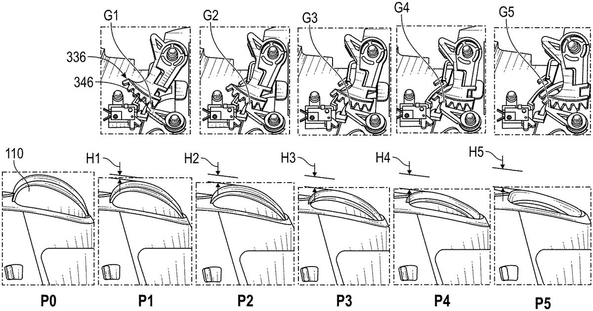
FIG. 7shows the trigger110in an undepressed position P0, as well as the trigger110with five different trigger-stop positions P1, P2, P3, P4, and P5that coincide with five positions G1, G2, G3, G4and G5, respectively of the clutch lever344of the clutch340relative to the gear334of the plunger330. The first position G1is the same as shown inFIG. 5, where the tooth346of the clutch lever344extends into the clearance space338between and engages the first tooth336A and second tooth336B. The first position G1provides a first maximum travel distance H1. In one implementation, the first maximum travel distance H1is between about 2 mm and about 3 mm (e.g., about 2.5 mm) and allows for the trigger110to be rotated about the axis of its hinge between about 3 degrees and about 8 degrees (e.g., about 5 degrees). The first position G1provides a minimum travel for the trigger110and provides a “hair” trigger position, where the trigger110does not need to travel far when pressed by a user to generate the same maximum electrical signal as when the trigger-stop is in a different position. The “hair” trigger position can advantageously allow the user to provide inputs in a videogame (e.g., shots in a shooting game) more quickly, which can lead to an improved gaming performance and experience for the user.
Advantageously, the user can effect the “hair” trigger position of the trigger-stop mechanism300by pressing quickly on the actuator (e.g., slider, post, lever)338and then releasing it without pressing the trigger110. This allows the clutch lever344to disengage the gear334and the plunger330to rotate (clockwise inFIG. 7, under spring force from the spring320that biases the plunger330toward the hair trigger position) so that the tooth346of the clutch lever344is aligned with the clearance space338between the first and second teeth346A,346B. When the actuator338is released the tooth346of the clutch lever344engages the gear334in the first position G1(e.g., the tooth346extends into the clearance space338between the first and second teeth336A,336B).
In the second position G2, the tooth346of the clutch lever344extends into the clearance space338between and engages the second tooth336B and third tooth336C. The second position G2provides a second maximum travel distance H2. In one implementation, the second maximum travel distance H2is between about 3 mm and about 5 mm (e.g., about 4 mm) and allows for the trigger110to be rotated about the axis of its hinge between about 5 degrees and about 10 degrees (e.g., about 9 degrees).
In the third position G3, the tooth346of the clutch lever344extends into the clearance space338between and engages the third tooth336C and fourth tooth336D. The third position G3provides a third maximum travel distance H3. In one implementation, the third maximum travel distance H3is between about 4 mm and about 7 mm (e.g., about 6 mm) and allows for the trigger110to be rotated about the axis of its hinge between about 10 degrees and about 14 degrees (e.g., about 12.5 degrees).
In the fourth position G4, the tooth346of the clutch lever344extends into the clearance space338between and engages the fourth tooth336D and fifth tooth336E. The fourth position G4provides a fourth maximum travel distance H4. In one implementation, the fourth maximum travel distance H4is between about 6 mm and about 9 mm (e.g., about 8 mm) and allows for the trigger110to be rotated about the axis of its hinge between about 13 degrees and about 18 degrees (e.g., about 16 degrees).
In the fifth position G5, the tooth346of the clutch lever344extends into the clearance space338between and engages the fifth tooth336E and sixth tooth336F. The fifth position G5is the same as the last position shown inFIG. 6and provides a fifth maximum travel distance H5. In one implementation, the fifth maximum travel distance H5is between about 8 mm and about 11 mm (e.g., about 9.5 mm) and allows for the trigger110to be rotated about the axis of its hinge between about 18 degrees and about 22 degrees (e.g., about 20 degrees).
With continued reference toFIG. 7, position G1provides the minimum travel distance for the trigger110and position G5provides the maximum travel distance for the trigger110, with positions G2, G3, and G4providing travel distances for the trigger110between the minimum travel distance of position G1and the maximum travel distance of position G5. In one implementation, the first position G1(the “hair” trigger position) has a travel span of between 5-25% of the travel span of the fifth position G5. ThoughFIG. 7shows the trigger-stop mechanism300with five positions G1-G5, one of skill in the art will recognize that the trigger-stop mechanism300can have fewer (e.g., three, four) positions or more (e.g., seven, eight, nine, ten) positions. For example, the gear332can have more teeth336than shown in the drawings to provide such additional positions when the clutch lever344engages the gear334.
As discussed above, the electronics200(e.g., processor175) can impose a signal mapping scheme/profile that is different for each trigger-stop position. Advantageously, when the trigger110,112is fully pressed in each trigger-stop position, the dynamic signal communicated by the controller100to the console is 100% of the possible output signal. The mapping scheme/profile can be a linear mapping profile. As the trigger110,112is gradually pulled from its resting position (e.g., 0% displacement along the travel path) to its fully pulled position (e.g., 100% displacement along the travel path), the signal communicated to the console by the controller100may gradually increase in strength (e.g., voltage) from 0% signal strength (i.e., no signal) to 100% signal strength (i.e., maximum output strength, e.g., 1 mV). The relationship between the relative degree of trigger pull and the signal output to the controller may be linear, or follow any other relationship or pattern (e.g., nonlinear, exponential, power, etc.).
The sensor170can be operatively coupled to the trigger110,112and can detect movement of the trigger110,112and generate a signal representative of such movements and communicate them to the electronics200(e.g., to the processor or MCU or microcontroller175). As discussed above, the sensor170can be a Hall Effect sensor. However, the sensor170can be any type of sensor suitable for detecting movements of the trigger110,112and transduce them into electrical signals representative of such movements, including but not limited to any one or more capacitive, resistive, inductive, piezoelectric, or optical sensors known in the art. For instance, the sensor170may include one or more of a proximity sensor, a rotation sensor, an encoder, a photoelectric sensor, a capacitive displacement sensor, an optical sensor, a strain gauge, and the like. The sensor170may detect trigger110,112movements in any manner, directly or indirectly, including by detecting movements of one or more objects extending from or operatively coupled to the trigger110,112.
Signals generated by sensor170responsive to the movements of the trigger110,112can be provided to processor175for processing. In some instances, the signal(s) generated by the sensor170undergo one or more pre-processing operations before being provided to the processor175. The signals generated by sensor170and provided as input to processor175may be directly related the trigger's position along the travel path (which may correspond directly to how far the trigger has been pulled/pressed back by the user). Processor175may process the signals received from the sensor170according to one or more signal mapping schemes/profiles before causing the transmitter185(via transmitter logic and circuitry configured for either wired or wireless communication) to transmit a corresponding signal to a connected gaming console.
The signal mapping scheme may be carried out or otherwise applied in any manner, including in some instances by processor175executing machine-machine-readable instructions stored in memory180(e.g., a computer program medium) that effectuate the signal mapping scheme. The signal ultimately conveyed to the gaming console (e.g., transmitted via transmitter185) may be directly related to how far back the trigger110,112, is pulled/pressed. The gaming console may receive the signal from the transmitter185and effectuate the gameplay functionality that corresponds to the trigger110,112movement detected (e.g., the degree of trigger pull detected).
Switch350may be operatively coupled with processor175such that the state/condition of the switch350is known to the processor175, and the processor175may process the signals generated by sensor170differently depending on the condition/state of the switch350. For example, processor175may process the signals generated by sensor170in accordance with different machine-readable instructions (or in accordance with an alternative algorithm or rule nested in the same set of instructions), based on the condition/state of the switch350.
It will be understood by one of ordinary skill in the art that processor175may cause a signal to be transmitted to a gaming console (or to a dongle connected thereto) in any manner, including over a wired or wireless (via transmitter185) channel. That is, in some implementations the signals/information about movement of the trigger110,112may be communicated to the gaming console via a wireless interface (e.g., a transmitter at the controller in communication with a receiver at the console), and in other implementations the signals/information about trigger movements may be may communicated to the gaming console via a wired interface (e.g., a cable).
The power source190of the controller100can enable operation of the various electronic components described above, among others. Power source190may be any power source. In some embodiments the power source190is a battery or other electrochemical cell. In other embodiments the power source190is provided by an AC line that may be plugged into an interface at the controller (not shown).
FIG. 9shows a videogame system900that can optionally include a display903(e.g., an electronic display, such as a television or computer monitor), a videogame console902, and one or more video game controllers, such as the videogame controller100with adjustable trigger stops described above. The videogame controller100, the videogame console902, and/or the display903can be electrically and/or mechanically coupled with one another to facilitate videogame play. The electrical circuitry included in the controller100may generate or alter an electrical signal based at least in part on movements of the trigger(s)110,112and convey that signal to the console902. The console902can process (e.g., with a computer processor) the signal it receives from the controller100and effectuate a gaming function or video game operation the signal is mapped to, which it can communicate to the display903. ThoughFIG. 9shows the controller100, console902and display903coupled via wired connections (e.g., via wires), one or more of the controller100, console902and display903can have circuitry (e.g., transmitter(s), receiver(s), transceiver(s)) that allow for wireless communication protocols to be employed between them. Moreover, in some implementations (not shown), the display903, the console902, and the controller100may all be comprised in a single device (e.g., a handheld videogaming device). Further, the controller100, console902and/or display903can have computing modules (e.g., circuitry, electronics), discussed below in connection withFIG. 10, for implementing the operations disclosed herein.
FIG. 10shows a computing module1200that may represent, for example, computing or processing capabilities found within desktop, laptop, notebook, gaming consoles, and tablet computers; hand-held computing devices (e.g., tablet computers, smart phones, etc.); wearable computing devices such as smartwatches; mainframes, supercomputers, workstations or servers; or any other type of special-purpose or general-purpose computing devices. Computing module1200can also represent computing capabilities embedded within or otherwise available to a given device. For instance, a computing module might be found in other electronic devices such as, for example, videogame consoles and videogaming controllers that can include some form of processing capability.
The computing module1200can include, for example, one or more processors (e.g., such as processor175), controllers, control modules, or other processing devices, such as a processor1204. Processor1204can be implemented using a general-purpose or special-purpose processing engine such as, for example, a microprocessor, controller, or other control logic. In the illustrated implementation, the processor1204is connected to a bus1202, although any communication medium can be used to facilitate interaction with other components of the computing module1200or to communicate externally of the computing module1200.
The computing module1200can also include one or more memory modules, simply referred to herein as memory1208(e.g., main memory). For example, preferably random access memory (RAM) or other dynamic memory, can be used for storing information and instructions to be executed by the processor1204. The memory1208can also be used for storing temporary variables or other intermediate information during execution of instructions to be executed by the processor1204. The computing module1200can likewise include a read only memory (“ROM”) or other static storage device coupled to the bus1202for storing static information and instructions for the processor1204.
The computing module1200can also include one or more information storage mechanism(s)1210, which can include, for example, a media drive1212and a storage unit interface1220. The media drive1212can include a drive or other mechanism to support fixed or removable storage media1214. For example, a hard disk drive, a solid state drive, a magnetic tape drive, an optical disk drive, a CD, DVD, or Blu-ray drive (R or RW), or other removable or fixed media drive might be provided. Accordingly, the storage media1214might include, for example, a hard disk, a solid state drive, magnetic tape, cartridge, optical disk, a CD, DVD, Blu-ray or other fixed or removable medium that is read by, written to or accessed by the media drive1212. The storage media1214can include a computer usable storage medium having stored therein computer software or data.
In other implementations, the information storage mechanism(s)1210can additionally or alternatively include other similar instrumentalities for allowing computer programs or other instructions or data to be loaded into computing module1200. Such instrumentalities might include, for example, a fixed or removable storage unit1222and an interface1220. Examples of such storage units1222and interfaces1220can include a program cartridge and cartridge interface, a removable memory (for example, a flash memory or other removable memory module) and memory slot, a PCMCIA slot and card, and other fixed or removable storage units1222and interfaces1220that allow software and data to be transferred from the storage unit1222to computing module1200.
The computing module1200can also include a communications interface1224. The communications interface1224can be used to allow software and data to be transferred between computing module1200and external devices. Examples of communications interface1224might include a modem or softmodem, a network interface (such as an Ethernet, network interface card, WiMedia, IEEE 802.XX or other interface), a communications port (such as for example, a USB port, IR port, RS232 port Bluetooth® interface, or other port), or other communications interface. Software and data transferred via the communications interface1224might typically be carried on signals, which can be electronic, electromagnetic (which includes optical) or other signals capable of being exchanged by a given communications interface1224. These signals might be provided to communications interface1224via a channel1228. This channel1228might carry signals and might be implemented using a wired or wireless communication medium. Some examples of a channel might include a phone line, a cellular link, an RF link, an optical link, a network interface, a local or wide area network, and other wired or wireless communications channels.
In this document, the terms “computer program medium” and “computer usable medium” are used to generally refer to transitory or non-transitory media such as, for example, memory1208, storage unit1220, media1214, and channel1228. These and other various forms of computer program media or computer usable media may be involved in carrying one or more sequences of one or more instructions to a processing device for execution. Such instructions embodied on the medium, are generally referred to as “computer program code” or a “computer program product” (which may be grouped in the form of computer programs or other groupings). When executed, such instructions might enable the computing module1200to perform features or functions of the present application as discussed herein.
While certain embodiments of the inventions have been described, these embodiments have been presented by way of example only, and are not intended to limit the scope of the disclosure. Indeed, the novel methods and systems described herein may be embodied in a variety of other forms. Furthermore, various omissions, substitutions and changes in the systems and methods described herein may be made without departing from the spirit of the disclosure. The accompanying claims and their equivalents are intended to cover such forms or modifications as would fall within the scope and spirit of the disclosure. Accordingly, the scope of the present inventions is defined only by reference to the appended claims.
Features, materials, characteristics, or groups described in conjunction with a particular aspect, embodiment, or example are to be understood to be applicable to any other aspect, embodiment or example described in this section or elsewhere in this specification unless incompatible therewith. All of the features disclosed in this specification (including any accompanying claims, abstract and drawings), and/or all of the steps of any method or process so disclosed, may be combined in any combination, except combinations where at least some of such features and/or steps are mutually exclusive. The protection is not restricted to the details of any foregoing embodiments. The protection extends to any novel one, or any novel combination, of the features disclosed in this specification (including any accompanying claims, abstract and drawings), or to any novel one, or any novel combination, of the steps of any method or process so disclosed.
Furthermore, certain features that are described in this disclosure in the context of separate implementations can also be implemented in combination in a single implementation. Conversely, various features that are described in the context of a single implementation can also be implemented in multiple implementations separately or in any suitable subcombination. Moreover, although features may be described above as acting in certain combinations, one or more features from a claimed combination can, in some cases, be excised from the combination, and the combination may be claimed as a subcombination or variation of a subcombination.
Moreover, while operations may be depicted in the drawings or described in the specification in a particular order, such operations need not be performed in the particular order shown or in sequential order, or that all operations be performed, to achieve desirable results. Other operations that are not depicted or described can be incorporated in the example methods and processes. For example, one or more additional operations can be performed before, after, simultaneously, or between any of the described operations. Further, the operations may be rearranged or reordered in other implementations. Those skilled in the art will appreciate that in some embodiments, the actual steps taken in the processes illustrated and/or disclosed may differ from those shown in the figures. Depending on the embodiment, certain of the steps described above may be removed, others may be added. Furthermore, the features and attributes of the specific embodiments disclosed above may be combined in different ways to form additional embodiments, all of which fall within the scope of the present disclosure. Also, the separation of various system components in the implementations described above should not be understood as requiring such separation in all implementations, and it should be understood that the described components and systems can generally be integrated together in a single product or packaged into multiple products.
For purposes of this disclosure, certain aspects, advantages, and novel features are described herein. Not necessarily all such advantages may be achieved in accordance with any particular embodiment. Thus, for example, those skilled in the art will recognize that the disclosure may be embodied or carried out in a manner that achieves one advantage or a group of advantages as taught herein without necessarily achieving other advantages as may be taught or suggested herein.
Conditional language, such as “can,” “could,” “might,” or “may,” unless specifically stated otherwise, or otherwise understood within the context as used, is generally intended to convey that certain embodiments include, while other embodiments do not include, certain features, elements, and/or steps. Thus, such conditional language is not generally intended to imply that features, elements, and/or steps are in any way required for one or more embodiments or that one or more embodiments necessarily include logic for deciding, with or without user input or prompting, whether these features, elements, and/or steps are included or are to be performed in any particular embodiment.
Conjunctive language such as the phrase “at least one of X, Y, and Z,” unless specifically stated otherwise, is otherwise understood with the context as used in general to convey that an item, term, etc. may be either X, Y, or Z. Thus, such conjunctive language is not generally intended to imply that certain embodiments require the presence of at least one of X, at least one of Y, and at least one of Z.
Language of degree used herein, such as the terms “approximately,” “about,” “generally,” and “substantially” as used herein represent a value, amount, or characteristic close to the stated value, amount, or characteristic that still performs a desired function or achieves a desired result. For example, the terms “approximately”, “about”, “generally,” and “substantially” may refer to an amount that is within less than 10% of, within less than 5% of, within less than 1% of, within less than 0.1% of, and within less than 0.01% of the stated amount. As another example, in certain embodiments, the terms “generally parallel” and “substantially parallel” refer to a value, amount, or characteristic that departs from exactly parallel by less than or equal to 15 degrees, 10 degrees, 5 degrees, 3 degrees, 1 degree, or 0.1 degree.
The scope of the present disclosure is not intended to be limited by the specific disclosures of preferred embodiments in this section or elsewhere in this specification, and may be defined by claims as presented in this section or elsewhere in this specification or as presented in the future. The language of the claims is to be interpreted broadly based on the language employed in the claims and not limited to the examples described in the present specification or during the prosecution of the application, which examples are to be construed as non-exclusive.
Of course, the foregoing description is that of certain features, aspects and advantages of the present invention, to which various changes and modifications can be made without departing from the spirit and scope of the present invention. Moreover, the devices described herein need not feature all of the objects, advantages, features and aspects discussed above. Thus, for example, those of skill in the art will recognize that the invention can be embodied or carried out in a manner that achieves or optimizes one advantage or a group of advantages as taught herein without necessarily achieving other objects or advantages as may be taught or suggested herein. In addition, while a number of variations of the invention have been shown and described in detail, other modifications and methods of use, which are within the scope of this invention, will be readily apparent to those of skill in the art based upon this disclosure. It is contemplated that various combinations or subcombinations of these specific features and aspects of embodiments may be made and still fall within the scope of the invention. Accordingly, it should be understood that various features and aspects of the disclosed embodiments can be combined with or substituted for one another in order to form varying modes of the discussed devices.
Claims
- A video game controller, comprising: a housing;a trigger movably coupled to the housing, the trigger pivotable about a first axis along a travel path in a direction transverse to the first axis from an undepressed position to a fully depressed position;and a trigger stop assembly comprising a clutch lever rotatable about a second axis, the clutch lever having a tooth that protrudes relative to a surface of the clutch lever, a plunger rotatable about a third axis and configured to define a travel limit of the trigger when the trigger is fully depressed and contacts at least a portion of the plunger, the plunger comprising a gear with a plurality of teeth spaced apart from each other and a clearance space between adjacent teeth configured to removably receive at least a portion of the tooth of the clutch lever therein, where the travel limit of the trigger is adjustable between a plurality of travel limit positions by inserting the tooth of the clutch lever in the clearance space between different teeth of the gear.
- The video game controller of claim 1 , wherein the plurality of travel limit positions includes a hair trigger limit position that allows a minimum travel distance for the trigger, a full travel trigger limit position that allows a maximum travel distance for the trigger, and at least one intermediate trigger limit position that allows an intermediate travel distance for the trigger that is greater than the minimum travel distance and smaller than the maximum travel distance.
- The video game controller of claim 2 , wherein the at least one intermediate trigger limit position includes three intermediate trigger limit positions.
- The video game controller of claim 2 , wherein the hair trigger limit position provides a maximum angular rotation for the trigger of 10% the maximum angular rotation for the trigger in the full travel trigger limit position.
- The video game controller of claim 4 , wherein the hair trigger limit position provides one or both of a maximum angular rotation for the trigger of 5 degrees and a maximum travel span of between 2 mm and 2.5 mm.
- The video game controller of claim 2 , wherein the plunger is biased to automatically move the plunger toward the hair trigger position upon actuation of the clutch lever.
- The video game controller of claim 1 , wherein actuation of the clutch lever causes the tooth to disengage from the gear, and where release of the clutch lever causes the tooth to engage the gear one of the plurality of travel limit positions.
- The video game controller of claim 1 , further comprising a clutch actuator attached to the clutch lever, at least a portion of the clutch actuator configured to extend through an opening in the housing, the clutch actuator selectively actuatable by a user to move the clutch lever to disengage the tooth of the clutch lever from the plunger to allow for an adjustment in the travel limit of the trigger.
- The video game controller of claim 8 , wherein the clutch actuator is a button.
- The video game controller of claim 1 , further comprising a processor configured to communicate an output signal to a gaming console based on movement of the trigger;and an electrical switch configured to communicate with the processor, wherein the processor is configured to map the travel span of the trigger for any of the plurality of travel limit positions to an output signal range proportionally such that the output signal communicated by the processor is the same when the trigger is fully depressed irrespective of the travel limit position set for the trigger.
- The video game controller of claim 10 , wherein the electrical switch is configured to detect the travel limit position for the trigger set by an engagement of the tooth of the clutch with the gear of the plunger, and to communicate a signal indicative of the set travel limit position to the processor.
- The video game controller of claim 10 , wherein the processor is configured to deactivate the trigger to prevent communication of the output signal to the gaming console while the clutch lever is actuated such that the tooth of the clutch lever is disengaged from the gear of the plunger.
- A video game controller, comprising: a housing;a trigger movably coupled to the housing, the trigger pivotable about a first axis along a travel path in a direction transverse to the first axis from an undepressed position to a fully depressed position;and a trigger stop assembly comprising a clutch lever rotatable about a second axis, a clutch actuator attached to the clutch lever and configured to at least partially extend through an opening in the housing, a plunger rotatable about a third axis and configured to define a travel limit of the trigger when the trigger is fully depressed and contacts at least a portion of the plunger, the plunger comprising a plurality of surfaces configured to releasably engage at least a portion of the clutch lever, where the travel limit of the trigger is adjustable between a plurality of travel limit positions by releasably engaging said at least a portion of the clutch lever with a different surface of the plurality of surfaces of the plunger, wherein the clutch actuator is selectively actuatable by a user to disengage the clutch lever from the plunger to allow for the adjustment in the travel limit of the trigger, wherein actuation of the clutch lever causes the clutch lever to disengage from the plunger, and where release of the clutch lever causes the clutch lever to engage with the plunger in one of the plurality of travel limit positions.
- The video game controller of claim 13 , wherein the plurality of travel limit positions includes a hair trigger limit position that allows a minimum travel distance for the trigger, a full travel trigger limit position that allows a maximum travel distance for the trigger, and a plurality of intermediate trigger limit positions that allows an intermediate travel distance for the trigger that is greater than the minimum travel distance and smaller than the maximum travel distance.
- The video game controller of claim 14 , wherein the hair trigger limit position provides a maximum angular rotation for the trigger of 10% the maximum angular rotation for the trigger in the full travel trigger limit position.
- The video game controller of claim 14 , wherein the plunger is biased to automatically move the plunger toward the hair trigger position upon actuation of the clutch lever.
- The video game controller of claim 14 , further comprising a processor configured to communicate an output signal to a gaming console based on movement of the trigger;and an electrical switch configured to communicate with the processor, wherein the processor is configured to map the travel span of the trigger for any of the plurality of travel limit positions to an output signal range proportionally such that the output signal communicated by the processor is the same when the trigger is fully depressed irrespective of the travel limit position set for the trigger.
- The video game controller of claim 17 , wherein the processor is configured to deactivate the trigger to prevent communication of the output signal to the gaming console while the clutch lever is disengaged from the plunger.
- A video game controller, comprising: a housing;a trigger movably coupled to the housing, the trigger pivotable about a first axis along a travel path in a direction transverse to the first axis from an undepressed position to a fully depressed position;and a trigger stop assembly comprising a clutch lever rotatable about a second axis, the clutch lever having a pawl, a plunger rotatable about a third axis and configured to define a travel limit of the trigger when the trigger is fully depressed and contacts at least a portion of the plunger, the plunger comprising a stepped end with a plurality of stepped surfaces spaced apart from each other, each of the stepped surfaces configured to selectively engage at least a portion of the pawl of the clutch lever, where the travel limit of the trigger is adjustable between a plurality of travel limit positions by engaging the pawl of the clutch lever with a different stepped surface of the plurality of stepped surfaces.
- The video game controller of claim 19 , wherein the plurality of travel limit positions includes a hair trigger limit position that allows a minimum travel distance for the trigger, a full travel trigger limit position that allows a maximum travel distance for the trigger, and at least one intermediate trigger limit position that allows an intermediate travel distance for the trigger that is greater than the minimum travel distance and smaller than the maximum travel distance.
Disclaimer: Data collected from the USPTO and may be malformed, incomplete, and/or otherwise inaccurate.