U.S. Pat. No. 11,285,394
COMPUTER-READABLE NON-TRANSITORY STORAGE MEDIUM HAVING INSTRUCTIONS STORED THEREIN, GAME APPARATUS, GAME SYSTEM, AND GAME PROCESSING METHOD
AssigneeNintendo Co Ltd
Issue DateMay 26, 2021
Illustrative Figure
Abstract
In an exemplary embodiment, a player object is caused to perform a posturing action of holding an item object in an input direction of a first direction input. When a second direction input is performed during the posturing action, a first swinging action of swinging the item object in the direction is performed. Further, when a going-way direction input in which a displacement amount with respect to the origin of an operation device and not greater than a first value exceeds the first value, and a return-way direction input in which the displacement amount becomes not greater than a second value after the going-way direction input have been performed within a first time, a second swinging action of swinging the item object in at least one of the going-way direction and the return-way direction is performed.
Description
DETAILED DESCRIPTION OF NON-LIMITING EXAMPLE EMBODIMENTS Hereinafter, the exemplary embodiment will be described. A game system according to an example of the exemplary embodiment is described below. An example of a game system1according to the exemplary embodiment includes a main body apparatus (an information processing apparatus, which functions as a game apparatus main body in the exemplary embodiment)2, a left controller3, and a right controller4. Each of the left controller3and the right controller4is attachable to and detachable from the main body apparatus2. That is, the game system1can be used as a unified apparatus obtained by attaching each of the left controller3and the right controller4to the main body apparatus2. Further, in the game system1, the main body apparatus2, the left controller3, and the right controller4can also be used as separate bodies (seeFIG. 2). Hereinafter, first, the hardware configuration of the game system1according to the exemplary embodiment is described, and then, the control of the game system1according to the exemplary embodiment is described. FIG. 1shows an example of the state where the left controller3and the right controller4are attached to the main body apparatus2. As shown inFIG. 1, each of the left controller3and the right controller4is attached to and unified with the main body apparatus2. The main body apparatus2is an apparatus for performing various processes (e.g., game processing) in the game system1. The main body apparatus2includes a display12. Each of the left controller3and the right controller4is an apparatus including operation sections with which a user provides inputs. FIG. 2shows an example of the state where each of the left controller3and the right controller4is detached from the main body apparatus2. As shown inFIGS. 1 and 2, the left controller3and the right controller4are attachable to and detachable from the main body apparatus2. It should be noted that hereinafter, the left controller3and the right controller4will occasionally ...
DETAILED DESCRIPTION OF NON-LIMITING EXAMPLE EMBODIMENTS
Hereinafter, the exemplary embodiment will be described.
A game system according to an example of the exemplary embodiment is described below. An example of a game system1according to the exemplary embodiment includes a main body apparatus (an information processing apparatus, which functions as a game apparatus main body in the exemplary embodiment)2, a left controller3, and a right controller4. Each of the left controller3and the right controller4is attachable to and detachable from the main body apparatus2. That is, the game system1can be used as a unified apparatus obtained by attaching each of the left controller3and the right controller4to the main body apparatus2. Further, in the game system1, the main body apparatus2, the left controller3, and the right controller4can also be used as separate bodies (seeFIG. 2). Hereinafter, first, the hardware configuration of the game system1according to the exemplary embodiment is described, and then, the control of the game system1according to the exemplary embodiment is described.
FIG. 1shows an example of the state where the left controller3and the right controller4are attached to the main body apparatus2. As shown inFIG. 1, each of the left controller3and the right controller4is attached to and unified with the main body apparatus2. The main body apparatus2is an apparatus for performing various processes (e.g., game processing) in the game system1. The main body apparatus2includes a display12. Each of the left controller3and the right controller4is an apparatus including operation sections with which a user provides inputs.
FIG. 2shows an example of the state where each of the left controller3and the right controller4is detached from the main body apparatus2. As shown inFIGS. 1 and 2, the left controller3and the right controller4are attachable to and detachable from the main body apparatus2. It should be noted that hereinafter, the left controller3and the right controller4will occasionally be referred to collectively as a “controller”.
FIG. 3is six orthogonal views showing an example of the main body apparatus2. As shown inFIG. 3, the main body apparatus2includes an approximately plate-shaped housing11. In the exemplary embodiment, a main surface (in other words, a surface on a front side, i.e., a surface on which the display12is provided) of the housing11has a substantially rectangular shape.
It should be noted that the shape and the size of the housing11are discretionary. As an example, the housing11may be of a portable size. Further, the main body apparatus2alone or the unified apparatus obtained by attaching the left controller3and the right controller4to the main body apparatus2may function as a mobile apparatus. The main body apparatus2or the unified apparatus may function as a handheld apparatus or a portable apparatus.
As shown inFIG. 3, the main body apparatus2includes the display12, which is provided on the main surface of the housing11. The display12displays an image generated by the main body apparatus2. In the exemplary embodiment, the display12is a liquid crystal display device (LCD). The display12, however, may be a display device of any type.
The main body apparatus2includes a touch panel13on the screen of the display12. In the exemplary embodiment, the touch panel13is of a type capable of receiving a multi-touch input (e.g., electrical capacitance type). However, the touch panel13may be of any type, and may be, for example, of a type capable of receiving a single-touch input (e.g., resistive film type).
The main body apparatus2includes speakers (i.e., speakers88shown inFIG. 6) within the housing11. As shown inFIG. 3, speaker holes11aand11bare formed on the main surface of the housing11. Then, sounds outputted from the speakers88are outputted through the speaker holes11aand11b.
Further, the main body apparatus2includes a left terminal17, which is a terminal for the main body apparatus2to perform wired communication with the left controller3, and a right terminal21, which is a terminal for the main body apparatus2to perform wired communication with the right controller4.
As shown inFIG. 3, the main body apparatus2includes a slot23. The slot23is provided on an upper side surface of the housing11. The slot23is so shaped as to allow a predetermined type of storage medium to be attached to the slot23. The predetermined type of storage medium is, for example, a dedicated storage medium (e.g., a dedicated memory card) for the game system1and an information processing apparatus of the same type as the game system1. The predetermined type of storage medium is used to store, for example, data (e.g., saved data of an application or the like) used by the main body apparatus2and/or a program (e.g., a program for an application or the like) executed by the main body apparatus2. Further, the main body apparatus2includes a power button28.
The main body apparatus2includes a lower terminal27. The lower terminal27is a terminal for the main body apparatus2to communicate with a cradle. In the exemplary embodiment, the lower terminal27is a USB connector (more specifically, a female connector). Further, when the unified apparatus or the main body apparatus2alone is mounted on the cradle, the game system1can display on a stationary monitor an image generated by and outputted from the main body apparatus2. Further, in the exemplary embodiment, the cradle has the function of charging the unified apparatus or the main body apparatus2alone mounted on the cradle. Further, the cradle has the function of a hub device (specifically, a USB hub).
FIG. 4is six orthogonal views showing an example of the left controller3. As shown inFIG. 4, the left controller3includes a housing31. In the exemplary embodiment, the housing31has a vertically long shape, i.e., is shaped to be long in an up-down direction (i.e., a y-axis direction shown inFIGS. 1 and 4). In the state where the left controller3is detached from the main body apparatus2, the left controller3can also be held in the orientation in which the left controller3is vertically long. The housing31has such a shape and a size that when held in the orientation in which the housing31is vertically long, the housing31can be held with one hand, particularly, the left hand. Further, the left controller3can also be held in the orientation in which the left controller3is horizontally long. When held in the orientation in which the left controller3is horizontally long, the left controller3may be held with both hands.
The left controller3includes a left analog stick (hereinafter, referred to as a “left stick”)32. As shown inFIG. 4, the left stick32is provided on a main surface of the housing31. The left stick32can be used as a direction input section with which a direction can be inputted. The user tilts the left stick32and thereby can input a direction corresponding to the direction of the tilt (and input a magnitude corresponding to the angle of the tilt). When the user releases the finger from the left stick32in a state where the left stick32is tilted, the left stick32returns to a neutral position by a return mechanism (e.g., a spring) (not shown). In the exemplary embodiment, the motion of this return is an instantaneously returning motion. However, in another exemplary embodiment, the displacement amount of the input may be gradually reduced such that the left stick32returns to the neutral position after an elapse of a predetermined time. It should be noted that the left controller3may include a directional pad, a slide stick that allows a slide input, or the like as the direction input section, instead of the analog stick. Further, in the exemplary embodiment, it is possible to provide an input by pressing the left stick32.
The left controller3includes various operation buttons. The left controller3includes four operation buttons33to36(specifically, a right direction button33, a down direction button34, an up direction button35, and a left direction button36) on the main surface of the housing31. Further, the left controller3includes a record button37and a “−” (minus) button47. The left controller3includes a first L-button38and a ZL-button39in an upper left portion of a side surface of the housing31. Further, the left controller3includes a second L-button43and a second R-button44, on the side surface of the housing31on which the left controller3is attached to the main body apparatus2. These operation buttons are used to give instructions depending on various programs (e.g., an OS program and an application program) executed by the main body apparatus2.
Further, the left controller3includes a terminal42for the left controller3to perform wired communication with the main body apparatus2.
FIG. 5is six orthogonal views showing an example of the right controller4. As shown inFIG. 5, the right controller4includes a housing51. In the exemplary embodiment, the housing51has a vertically long shape, i.e., is shaped to be long in the up-down direction. In the state where the right controller4is detached from the main body apparatus2, the right controller4can also be held in the orientation in which the right controller4is vertically long. The housing51has such a shape and a size that when held in the orientation in which the housing51is vertically long, the housing51can be held with one hand, particularly the right hand. Further, the right controller4can also be held in the orientation in which the right controller4is horizontally long. When held in the orientation in which the right controller4is horizontally long, the right controller4may be held with both hands.
Similarly to the left controller3, the right controller4includes a right analog stick (hereinafter, referred to as a “right stick”)52as a direction input section. In the exemplary embodiment, the right stick52has the same configuration as that of the left stick32of the left controller3. Further, the right controller4may include a directional pad, a slide stick that allows a slide input, or the like, instead of the analog stick. Further, similarly to the left controller3, the right controller4includes four operation buttons53to56(specifically, an A-button53, a B-button54, an X-button55, and a Y-button56) on a main surface of the housing51. Further, the right controller4includes a “+” (plus) button57and a home button58. Further, the right controller4includes a first R-button60and a ZR-button61in an upper right portion of a side surface of the housing51. Further, similarly to the left controller3, the right controller4includes a second L-button65and a second R-button66.
Further, the right controller4includes a terminal64for the right controller4to perform wired communication with the main body apparatus2.
FIG. 6is a block diagram showing an example of the internal configuration of the main body apparatus2. The main body apparatus2includes components81to91,97, and98shown inFIG. 6in addition to the components shown inFIG. 3. Some of the components81to91,97, and98may be mounted as electronic components on an electronic circuit board and accommodated in the housing11.
The main body apparatus2includes a processor81. The processor81is an information processing section for executing various types of information processing to be executed by the main body apparatus2. For example, the processor81may be composed only of a CPU (Central Processing Unit), or may be composed of a SoC (System-on-a-chip) having a plurality of functions such as a CPU function and a GPU (Graphics Processing Unit) function. The processor81executes an information processing program (e.g., a game program) stored in a storage section (specifically, an internal storage medium such as a flash memory84, an external storage medium attached to the slot23, or the like), thereby performing the various types of information processing.
The main body apparatus2includes the flash memory84and a DRAM (Dynamic Random Access Memory)85as examples of internal storage media built into the main body apparatus2. The flash memory84and the DRAM85are connected to the processor81. The flash memory84is a memory mainly used to store various data (or programs) to be saved in the main body apparatus2. The DRAM85is a memory used to temporarily store various data used for information processing.
The main body apparatus2includes a slot interface (hereinafter, abbreviated as “I/F”)91. The slot I/F91is connected to the processor81. The slot I/F91is connected to the slot23, and in accordance with an instruction from the processor81, reads and writes data from and to the predetermined type of storage medium (e.g., a dedicated memory card) attached to the slot23.
The processor81appropriately reads and writes data from and to the flash memory84, the DRAM85, and each of the above storage media, thereby performing the above information processing.
The main body apparatus2includes a network communication section82. The network communication section82is connected to the processor81. The network communication section82communicates (specifically, through wireless communication) with an external apparatus via a network. In the exemplary embodiment, as a first communication form, the network communication section82connects to a wireless LAN and communicates with an external apparatus, using a method compliant with the Wi-Fi standard. Further, as a second communication form, the network communication section82wirelessly communicates with another main body apparatus2of the same type, using a predetermined method for communication (e.g., communication based on a unique protocol or infrared light communication). It should be noted that the wireless communication in the above second communication form achieves the function of enabling so-called “local communication” in which the main body apparatus2can wirelessly communicate with another main body apparatus2placed in a closed local network area, and the plurality of main body apparatuses2directly communicate with each other to transmit and receive data.
The main body apparatus2includes a controller communication section83. The controller communication section83is connected to the processor81. The controller communication section83wirelessly communicates with the left controller3and/or the right controller4. The communication method between the main body apparatus2and the left controller3and the right controller4is discretionary. In the exemplary embodiment, the controller communication section83performs communication compliant with the Bluetooth (registered trademark) standard with the left controller3and with the right controller4.
The processor81is connected to the left terminal17, the right terminal21, and the lower terminal27. When performing wired communication with the left controller3, the processor81transmits data to the left controller3via the left terminal17and also receives operation data from the left controller3via the left terminal17. Further, when performing wired communication with the right controller4, the processor81transmits data to the right controller4via the right terminal21and also receives operation data from the right controller4via the right terminal21. Further, when communicating with the cradle, the processor81transmits data to the cradle via the lower terminal27. As described above, in the exemplary embodiment, the main body apparatus2can perform both wired communication and wireless communication with each of the left controller3and the right controller4. Further, when the unified apparatus obtained by attaching the left controller3and the right controller4to the main body apparatus2or the main body apparatus2alone is attached to the cradle, the main body apparatus2can output data (e.g., image data or sound data) to the stationary monitor or the like via the cradle.
Here, the main body apparatus2can communicate with a plurality of left controllers3simultaneously (in other words, in parallel). Further, the main body apparatus2can communicate with a plurality of right controllers4simultaneously (in other words, in parallel). Thus, a plurality of users can simultaneously provide inputs to the main body apparatus2, each using a set of the left controller3and the right controller4. As an example, a first user can provide an input to the main body apparatus2using a first set of the left controller3and the right controller4, and simultaneously, a second user can provide an input to the main body apparatus2using a second set of the left controller3and the right controller4.
The main body apparatus2includes a touch panel controller86, which is a circuit for controlling the touch panel13. The touch panel controller86is connected between the touch panel13and the processor81. On the basis of a signal from the touch panel13, the touch panel controller86generates data indicating the position at which a touch input has been performed, for example, and outputs the data to the processor81.
Further, the display12is connected to the processor81. The processor81displays a generated image (e.g., an image generated by executing the above information processing) and/or an externally acquired image on the display12.
The main body apparatus2includes a codec circuit87and speakers (specifically, a left speaker and a right speaker)88. The codec circuit87is connected to the speakers88and a sound input/output terminal25and also connected to the processor81. The codec circuit87is a circuit for controlling the input and output of sound data to and from the speakers88and the sound input/output terminal25.
The main body apparatus2includes a power control section97and a battery98. The power control section97is connected to the battery98and the processor81. Further, although not shown inFIG. 6, the power control section97is connected to components of the main body apparatus2(specifically, components that receive power supplied from the battery98, the left terminal17, and the right terminal21). Based on a command from the processor81, the power control section97controls the supply of power from the battery98to the above components.
Further, the battery98is connected to the lower terminal27. When an external charging device (e.g., the cradle) is connected to the lower terminal27, and power is supplied to the main body apparatus2via the lower terminal27, the battery98is charged with the supplied power.
FIG. 7is a block diagram showing examples of the internal configurations of the main body apparatus2, the left controller3, and the right controller4. It should be noted that the details of the internal configuration of the main body apparatus2are shown inFIG. 6and therefore are omitted inFIG. 7.
The left controller3includes a communication control section101, which communicates with the main body apparatus2. As shown inFIG. 7, the communication control section101is connected to components including the terminal42. In the exemplary embodiment, the communication control section101can communicate with the main body apparatus2through both wired communication via the terminal42and wireless communication not via the terminal42. The communication control section101controls the method for communication performed by the left controller3with the main body apparatus2. That is, when the left controller3is attached to the main body apparatus2, the communication control section101communicates with the main body apparatus2via the terminal42. Further, when the left controller3is detached from the main body apparatus2, the communication control section101wirelessly communicates with the main body apparatus2(specifically, the controller communication section83). The wireless communication between the communication control section101and the controller communication section83is performed in accordance with the Bluetooth (registered trademark) standard, for example.
Further, the left controller3includes a memory102such as a flash memory. The communication control section101includes, for example, a microcomputer (or a microprocessor) and executes firmware stored in the memory102, thereby performing various processes.
The left controller3includes buttons103(specifically, the buttons33to39,43,44, and47). Further, the left controller3includes the left stick32. Each of the buttons103and the left stick32outputs information regarding an operation performed on itself to the communication control section101repeatedly at appropriate timings.
The left controller3includes inertial sensors. Specifically, the left controller3includes an acceleration sensor104. Further, the left controller3includes an angular velocity sensor105. In the exemplary embodiment, the acceleration sensor104detects the magnitudes of accelerations along predetermined three axial (e.g., xyz axes shown inFIG. 4) directions. It should be noted that the acceleration sensor104may detect an acceleration along one axial direction or accelerations along two axial directions. In the exemplary embodiment, the angular velocity sensor105detects angular velocities about predetermined three axes (e.g., the xyz axes shown inFIG. 4). It should be noted that the angular velocity sensor105may detect an angular velocity about one axis or angular velocities about two axes. Each of the acceleration sensor104and the angular velocity sensor105is connected to the communication control section101. Then, the detection results of the acceleration sensor104and the angular velocity sensor105are outputted to the communication control section101repeatedly at appropriate timings.
The communication control section101acquires information regarding an input (specifically, information regarding an operation or the detection result of the sensor) from each of input sections (specifically, the buttons103, the left stick32, and the sensors104and105). The communication control section101transmits operation data including the acquired information (or information obtained by performing predetermined processing on the acquired information) to the main body apparatus2. It should be noted that the operation data is transmitted repeatedly, once every predetermined time. It should be noted that the interval at which the information regarding an input is transmitted from each of the input sections to the main body apparatus2may or may not be the same.
The above operation data is transmitted to the main body apparatus2, whereby the main body apparatus2can obtain inputs provided to the left controller3. That is, the main body apparatus2can determine operations on the buttons103and the left stick32based on the operation data. Further, the main body apparatus2can calculate information regarding the motion and/or the orientation of the left controller3based on the operation data (specifically, the detection results of the acceleration sensor104and the angular velocity sensor105).
The left controller3includes a power supply section108. In the exemplary embodiment, the power supply section108includes a battery and a power control circuit. Although not shown inFIG. 7, the power control circuit is connected to the battery and also connected to components of the left controller3(specifically, components that receive power supplied from the battery).
As shown inFIG. 7, the right controller4includes a communication control section111, which communicates with the main body apparatus2. Further, the right controller4includes a memory112, which is connected to the communication control section111. The communication control section111is connected to components including the terminal64. The communication control section111and the memory112have functions similar to those of the communication control section101and the memory102, respectively, of the left controller3. Thus, the communication control section111can communicate with the main body apparatus2through both wired communication via the terminal64and wireless communication not via the terminal64(specifically, communication compliant with the Bluetooth (registered trademark) standard). The communication control section111controls the method for communication performed by the right controller4with the main body apparatus2.
The right controller4includes input sections similar to the input sections of the left controller3. Specifically, the right controller4includes buttons113, the right stick52, and inertial sensors (an acceleration sensor114and an angular velocity sensor115). These input sections have functions similar to those of the input sections of the left controller3and operate similarly to the input sections of the left controller3.
The right controller4includes a power supply section118. The power supply section118has a function similar to that of the power supply section108of the left controller3and operates similarly to the power supply section108.
[Outline of Game Processing of Exemplary Embodiment]
Next, the outline of operation of game processing executed by the game system1according to the exemplary embodiment will be described. In the above game system1, the left controller3and the right controller4are attachable to and detachable from the main body apparatus2. When a game is played in the state where the left controller3and the right controller4are attached to the main body apparatus2, the game image is outputted to the display12. When the main body apparatus2alone in the state where the left controller3and the right controller4are detached from the main body apparatus2is attached to the cradle, the main body apparatus2can also output the game image to a stationary monitor or the like via the cradle. In the exemplary embodiment, description is given of an example case where the game is played in the latter form, i.e., in the form in which the main body apparatus2alone in the state where the left controller3and the right controller4are detached from the main body apparatus2is attached to the cradle and the main body apparatus2outputs the game image and the like to the stationary monitor or the like via the cradle.
The game (hereinafter, referred to as “this game”) assumed in the exemplary embodiment is an action adventure game in which a player object is operated in a virtual three-dimensional space.FIG. 8is an example of a game screen assumed in the exemplary embodiment. InFIG. 8, how the three-dimensional virtual game space is seen is shown on the game screen. In the three-dimensional virtual game space, a player object201is present and an image seen from behind and captured by a virtual camera is displayed. The entire body of the player object201is displayed on the game screen. Further, the player object201carries a sword204(hereinafter, simply referred to as a sword) on the back. The sword204is in a state of being in a sheath, and the sword204can be drawn from the sheath through an operation described later. Hereinafter, drawing the sword204from the sheath will be referred to as “sword drawing”.FIG. 9shows an example of the screen regarding the player object201after sword drawing has been performed.FIG. 9shows a state where the sword204is gripped with the right hand of the player object201. In this state, the player can move the sword204within a range based on the movable range of the right arm of the player object201.
In this game, the player object201can be caused to perform a movement of “swinging” the sword204. Thus, the player object201can attack a predetermined enemy object (not shown) by swinging the sword204. Further, the player object201can also “slash” a predetermined object other than an enemy, such as a plant object. The processing according to the exemplary embodiment is processing regarding an operation for causing the player object201to perform a movement of “swinging” the sword204. In the description below, the movement of “swinging” the sword204will be referred to as a “sword swinging movement”. The sword swinging movement includes two actions, i.e., a “posturing action” and a “swinging action” described later.
Next, before describing specific operation contents, the “state (in the game)” of the player object201related to the movement of “swinging” as described above, and the transition thereof will be described. Hereinafter, the state in the game of the player object201will be referred to as a “PO state (player object state)”. First, in this game, the PO state where the sword204is in the sheath as shown inFIG. 8is referred to as a “non-sword-drawn state”. In this state, when a predetermined sword drawing operation is performed, a sword drawing motion is displayed, and then, as shown inFIG. 9, the player object201enters a state where the player object201has the sword204with the right hand. In the exemplary embodiment, this PO state is referred to as a “posturing state”. In the posturing state, the player can cause the player object201to perform a posturing action. The posturing action is an action of changing the position and orientation of the sword204in the movable range of the right arm of the player object201. That is, the posturing action is such an action in which the player object201takes a posture of holding the sword before swinging the sword.FIG. 10shows an example in which the player object201takes a posture of holding the sword204with the tip thereof directed toward the right direction. In the posturing state, the orientation of the sword204can be changed by an operation described later. Then, in the posturing state, when a predetermined condition has been satisfied (i.e., when a predetermined operation has been performed), a motion of actually swinging the sword204is displayed. Hereinafter, the PO state in the middle of swinging the sword204will be referred to as a “swinging state”. Further, the motion of swinging the sword will be referred to as a “swinging action”.FIG. 11shows an example of the player object201in the “swinging state”. In the example inFIG. 11, a swinging action of horizontal slashing from the right direction toward the left direction is shown.
[Operation Mode]
Next, specific operations for causing the movement as described above are described. In the exemplary embodiment, two operation modes are provided for causing the movements as described above to be performed. A first operation mode is an operation mode that mainly uses the right stick52provided to the right controller4. A second operation mode is an operation mode that uses inertial sensors of the right controller4. It should be noted that, in the exemplary embodiment, either one of these operation modes is set. For example, on a game setting screen, an item for setting an operation mode is provided, and either one of the operation modes is designated. Therefore, when the first operation mode is set, operation according to the second operation mode cannot be performed. The same applies vice versa.
[Second Operation Mode]
Next, each operation mode will be described. For convenience of description, the second operation mode is described first. A described above, the second operation mode uses inertial sensors of the right controller4. Specifically, in the second operation mode, the player regards the right controller4as the sword204, and can change the orientation of or swing the sword204by tilting or swinging the right controller4.
In an example of the operation, first, in the non-sword-drawn state, when the player presses a predetermined button, the player object201performs sword drawing and the PO state transitions to the posturing state. At this time, on the basis of outputs from the inertial sensors, the orientation of the right controller4is calculated, and the orientation is reflected in the orientation of the sword204. For example, the inertial sensors include a gyro sensor, and the orientation of the right controller4is calculated on the basis of the angular velocity detected by the gyro sensor. Here, a case where the orientation as shown inFIG. 9has been established as a result of a sword drawing operation is assumed. Next, it is assumed that, when the screen is in the state as shown inFIG. 9, the player has horizontally stretched the right arm and the right controller4has also taken a substantially horizontal orientation. In this case, the orientation of the right controller4is calculated on the basis of outputs from the inertial sensors, and this orientation is reflected in the position and orientation of the sword204. As a result, the position and orientation of the sword204(and the player object201) are changed to those as shown inFIG. 10.
Further, it is assumed that, when the game screen is in the state as shown inFIG. 10, the player swings the right controller4in the left direction at not less than a predetermined speed. In this case, a motion of swinging the controller is detected on the basis of outputs from the inertial sensor. For example, the inertial sensors include an acceleration sensor, and it is determined that the controller has been swung, on the basis of determination that an acceleration having not less than a predetermined value has been detected. As a result, the PO state transitions to the swinging state, and change in the orientation of the right controller4in this swinging motion is reflected in change in the position and orientation of the sword204. As a result, the player object201performs the swinging action as shown inFIG. 11.
As described above, in the second operation mode, on the basis of outputs of the inertial sensors, the orientation of the right controller4is calculated, and swinging is determined. Then, the calculated orientation of the right controller4is reflected in the sword204, whereby a series of actions comprising the above-described posturing action and swinging action are realized. Accordingly, the sword204can be swung by moving the right controller4itself, and thus, an intuitive operation can be performed. In addition, a user experience as if the user was actually swinging the sword can be provided.
[First Operation Mode]
As described above, in the second operation mode, the inertial sensors are used, whereby an operation method of moving the right controller4itself is provided. Here, in the game system1according to the exemplary embodiment, as described above, the left controller3and the right controller4are attachable to and detachable from the main body apparatus2. Therefore, there are also cases where the game screen is displayed on the display12when the game is played in the state where the left controller3and the right controller4are attached to the main body apparatus2as shown inFIG. 1. In such a case, it is considered that the operations using the inertial sensors of the right controller4are difficult to be performed. In addition, there may be a case where the player does not like in the first place the operation method such as the second operation mode. Therefore, the first operation mode is provided in the exemplary embodiment. In this operation mode, it is possible to perform a series of actions comprising the posturing action and the swinging action, as in the case of the second operation mode, through a simple direction input operation using the right stick52. Therefore, even in the state where the left controller3and the right controller4are attached to the main body apparatus2, it is possible to cause the player object201to perform movement of swinging the sword204, as in the case of the second operation mode. Alternatively, even in a case where the player does not use (or does not want to use) the second operation mode although the main body apparatus2is in the state of not having the controllers attached thereto, it is possible to cause the player object201to perform movement of swinging the sword204.
Next, the outline of operations and processing in the first operation mode is described. First, handling of operation input data of the right stick52is described. In the first operation mode, operation input data from the right stick52is obtained as a two-dimensional value. That is, it is assumed that operation input data from the right stick52is obtained as a two-dimensional value of (x, y). Then, in the exemplary embodiment, a two-dimensional plane (hereinafter, stick plane) of a coordinate system in which, with the right stick52viewed from immediately above, the right direction is the x-axis positive direction and the up direction is the y-axis positive direction, is assumed. In this stick plane, the position (origin) when the right stick52is in a neutral state (the state where the right stick52is not tilted in any direction) is assumed to be the center of the stick plane. Further, in the exemplary embodiment, the range of the each value of the above (x, y) is assumed to be a range of −1 to +1 with respect to 0, which is the center of the stick plane (the left and down directions are negative directions, and the right and up directions are positive directions). In this case, the vector (hereinafter, referred to as an input vector) connecting this origin and the coordinate represented by the above-described two-dimensional value indicates the input strength and the input direction. That is, the length of the input vector indicates the degree of tilt of the right stick52, and the orientation of the input vector indicates the input direction.
Next, the relationship between the input content of the right stick52and the posturing action and swinging action is described. In the exemplary embodiment, the stick plane is associated with an x-y plane that is defined with the player object201seen from behind.FIG. 12shows the correspondence between the stick plane and the x-y plane (hereinafter, referred to as a player object plane). InFIG. 12, a circular stick plane is shown on the left side. Further, inFIG. 12, the player object201is shown on the right, and the player object plane is indicated by a dotted line surrounding the player object201. It should be noted that the outer circumference of the circle of the stick plane indicates the input limit (where the right stick52is tilted to the maximum) of the right stick52. In other words, the stick plane indicates the movable range of the stick. InFIG. 12, a plane in which the player object201is seen from behind is assumed, and correspondence in which a substantial center portion of the player object201matches the center of the stick plane is assumed. It should be noted that, in another example, a root portion of the right arm and the center of the stick plane may be associated with each other.
On the assumption of the above correspondence relationship, the following operation can be performed in the first operation mode. First, it is assumed that the operation of the sword drawing is the same as that in the second operation mode described above. When sword drawing has been performed, a predetermined sword drawing motion is displayed, and then, the PO state transitions to the posturing state. In this posturing state, the orientation of the sword204can be changed in accordance with an input of the right stick52. In the case where the input of the right stick52is neutral, a predetermined orientation corresponding thereto is taken.
Next, an example of movement (orientation change) of the sword204(other than that in the swinging action) in the posturing state is described.FIG. 13shows an example of a case where the right stick52has been tilted to the maximum in the right direction. InFIG. 13, the stick plane and the input vector thereof (arrow) are shown on the left side, and the orientation of the sword204(and the player object201) corresponding to this input is shown on the right side. As shown inFIG. 13, when the right stick52has been tilted to the maximum in the right direction, the orientation of the sword204is also changed, in accordance with this, to an orientation in which the tip of the sword204is directed to the right. It should be noted that the position in the depth direction (on the z axis) may be any position corresponding to the game content, but basically, is a position that is influenced by the movable range of the right arm of the player object201having the sword204.
A case in which, from the orientation shown inFIG. 13, only the input direction of the right stick52is further rotated counter-clockwise while the right stick52is tilted to the maximum, is assumed.FIGS. 14 to 17show examples of changes in the orientation in this case.FIG. 14shows a case where the input direction of the right stick52is an upper right direction. In this case, the tip of the sword204is also in an orientation directed to the upper right direction on the player object plane. Further, when the input direction of the right stick52is changed to the straight up direction, the orientation of the tip of the sword204is changed to an orientation directed to the straight up direction in the player object plane, as shown inFIG. 15. Further, when the input direction of the right stick52is changed to the left direction, the tip of the sword204is changed to an orientation directed to the left direction in the player object plane, as shown inFIG. 16. Further, when the input direction of the right stick52is changed to the straight down direction, the orientation of the tip of the sword204is changed to an orientation directed to the straight down direction in the player object plane, as shown inFIG. 17.
In this manner, in the first operation mode, in the posturing state, the posturing action can be performed by an input operation of the right stick52. That is, the orientation of the sword204can be changed such that (the tip of) the sword204is directed to a direction corresponding to the direction input of the right stick52.
Next, the swinging action in the first operation mode is described. In the posturing state, when an operation satisfying a predetermined condition is performed, the player object201can be caused to perform the swinging action. In the exemplary embodiment, as the operation for causing the swinging action to be performed, the following three types of operation methods are provided.
(1) Sword swinging movement by “flicking operation”.
(2) Sword swinging movement by an input operation (hereinafter, opposite-direction input operation) in which, from a state where the right stick52is tilted to the maximum up to the end in a predetermined direction, the right stick52is tilted to the maximum in the direction opposite to the predetermined direction within a predetermined time.
(3) Sword swinging movement by “release operation”.
Hereinafter, the outline of each operation method is described.
First, the flicking operation in the exemplary embodiment is assumed to be an operation of flicking the right stick52. That is, when the input trajectory of the right stick52is a trajectory that has changed as “center→end→center” as shown inFIG. 18within several frames, it is determined that the flicking operation has been performed. The example inFIG. 18is an operation example of flicking the right stick52in the left direction. Here, the trajectory of the flicking operation can be regarded as a going and return way composed of a going way directed from the center to the outer side (end of the stick plane) and a return way returning from the outer side toward the center. As for the going way, it is also possible to say that the input is an input in the going-way direction that causes the state (the state where the right stick52is at the center) where the displacement amount of the right stick52from the center of the stick plane is not greater than a first value, to be changed to a state where the displacement amount exceeds at least the first value. As for the return way, it is also possible to say that the input is an input in the return way direction that realizes a state where the displacement amount is not greater than a second value after the input in the going-way direction. Then, when the two direction inputs in the going way and the return way have been performed within a predetermined number of frames, it is possible to determine that the flicking operation has been performed. In the exemplary embodiment, on the basis of an input history of the right stick52corresponding to the last several tens of frames, it is determined whether or not a direction input realizing an input trajectory that can be regarded as having been caused by a flicking operation has been performed. It should be noted that, in the exemplary embodiment, the direction (hereinafter, referred to as a “swing direction”) in which the sword204is swung in the case of the flicking operation is assumed to be the direction (going-way direction) in which the right stick52has been flicked. However, in another exemplary embodiment, the return-way direction may be used as the swing direction.
Next, the outline of the opposite-direction input operation is described. The opposite-direction input operation in the exemplary embodiment is assumed to be an operation in which, from a state (the state where the sword is held in a certain direction during posturing) where the right stick52is tilted to the maximum up to the end in a predetermined direction, the right stick52is tilted to the maximum up to the end in the opposite direction thereto. For example, assumed is an operation in which, from a state (the state where the right stick52is tilted to the maximum up to the right end) where the sword is held in the right direction during posturing, the right stick52is tilted to the maximum up to the left end in the direction opposite to the posturing direction within several frames. In this case, the input trajectory of the right stick52is determined to have changed as “end in a predetermined direction→end in the opposite direction” in several frames as shown inFIG. 19, whereby it is determined that the opposite-direction input operation has been performed. When the input trajectory is considered in terms of displacement amount, for example, if the displacement amount of the right stick52has changed, within several frames, from a displacement amount indicating that the right stick52is at an end to a displacement amount indicating that the right stick52is at the center, and then, the displacement amount has changed to a displacement amount indicating that the right stick52is at an end in the opposite direction, it can be determined that the opposite-direction input operation has been performed. For example, a direction input in which a state where the displacement amount in the right direction from the center of the stick plane is not less than 0.5 has changed to a state where the displacement amount is not greater than 0.5 and then becomes not less than 0.5 in the left direction from the center, has been performed within several frames, it can be determined that the opposite-direction input operation has been performed. It should be noted that the swing direction in the opposite-direction input operation is the “opposite direction” described above.
Next, the outline of the release operation is described. The release operation in the exemplary embodiment is assumed to be an operation in which, in a state where the right stick52is tilted to the maximum up to the end in a predetermined direction, the finger is released from the right stick52(direction input by the right stick52has been canceled). In this case, the right stick52returns to the center (origin) of the above stick plane due to the return mechanism provided to the analog stick. Therefore, when the input trajectory of the right stick52has been realized as “end→center” within several frames as shown inFIG. 20, it is determined that the release operation has been performed. The example inFIG. 20shows a case where, in a state where the right stick52is tilted to the maximum up to the right end, the finger is released from the right stick52. It should be noted that the swing direction in this release operation is the direction in which the right stick52returns to the center after the release.
In this game, separately from the swinging action described above, it is also possible to cause the player object201to perform a movement of “rotating slash” as one of “special actions”. In the exemplary embodiment, as a “rotating slash operation” for causing this movement to be performed, when the input trajectory of the right stick52has become “outer side→outer side in opposite direction→original position” as shown inFIG. 21within several frames, it is determined that the rotating slash operation has been performed. When such an operation has been performed, a movement of rotating the sword204about the axis orthogonal to the direction, in the game space, that corresponds to the direction (going-way direction or return-way direction), in the stick plane, that is indicated by the input trajectory, is performed. In the example shown inFIG. 21, displacement occurs as “right end→left end→right end”, and in the trajectory, the displacement occurs along the horizontal direction in the stick plane. In such an operation, a movement in which the player object201swings the sword204while rotating about the gravity axis (the axis orthogonal to the horizontal direction) in the virtual game space, is performed. In other words, a rotating slash of rotating the sword204in the horizontal direction is performed. Further, for example, in the case of the input trajectory being “upper end→lower end→upper end”, a rotating slash of rotating the sword204in the vertical direction in the game space is performed.
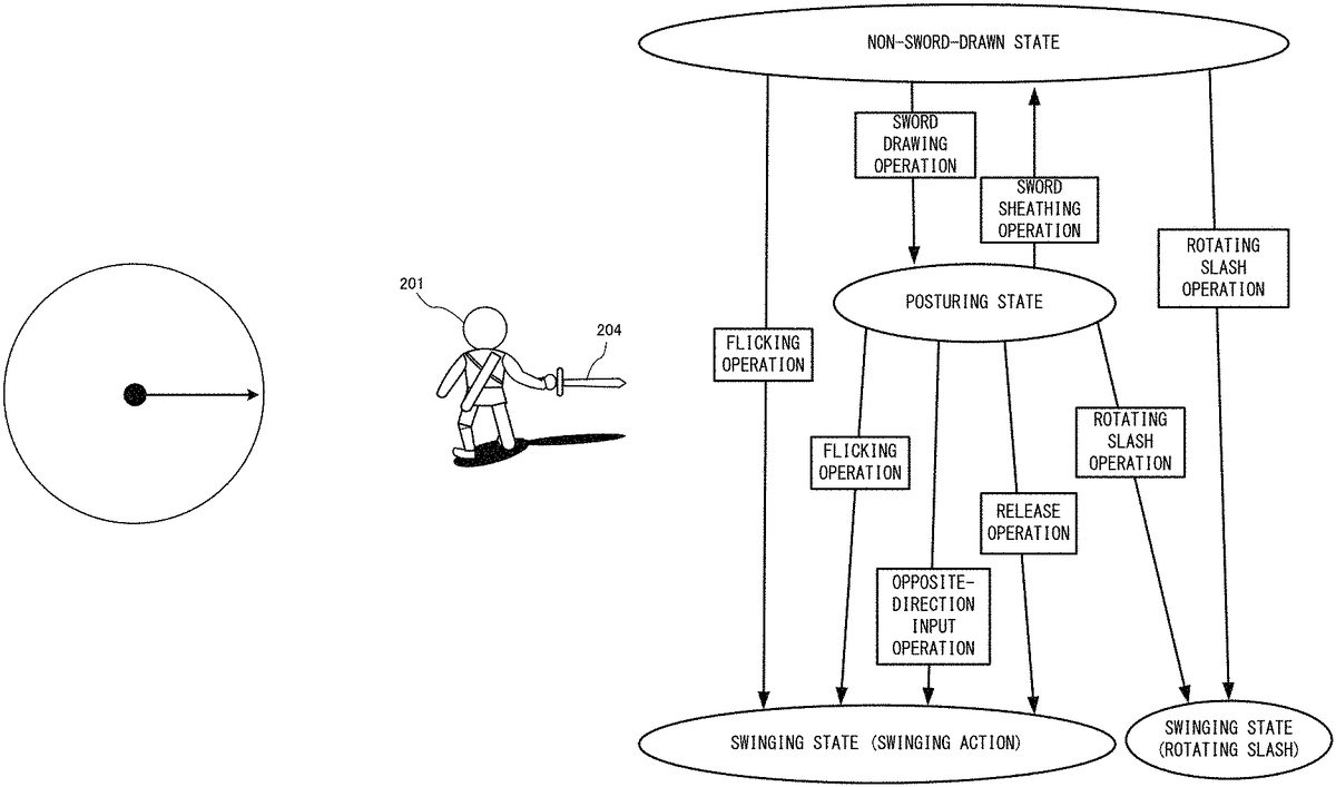
Here, the transition relationship between various operations in the first operation mode as described above and the PO states based on these operations is shownFIG. 22. As shown inFIG. 22, when the “sword drawing operation” is performed in the non-sword-drawn state, the PO state transitions to the above-described posturing state. When the “sword sheathing operation for putting the sword204in the sheath is performed in the posturing state, the PO state transitions to the non-sword-drawn state. Further, when any one of the “flicking operation”, the “opposite-direction input operation”, and the “release operation” as described above is performed in the posturing state, the PO state transitions to a swinging state (the state where the above swinging action is performed). Further, also when the “rotating slash operation” is performed in the posturing state, the PO state transitions to a swinging state. However, the movement performed in this case is a rotating slash movement as a special action, which is different from the above-described swinging action. When the swinging action or the special action ends, the PO state returns from the swinging state to the posturing state.
Further, also when the “flicking operation” as described above has been performed in the non-sword-drawn state, the PO state immediately transitions to a swinging state (the state where the above swinging action is performed). Also when the “rotating slash operation” has been performed in the non-sword-drawn state, the PO state immediately transitions to a swinging state as the rotating slash movement. Further, in the exemplary embodiment, it is assumed that, in a case where the PO state has transitioned from the non-sword-drawn state to a swinging state, when the swinging action or the special action ends, the PO state transitions to the posturing state. However, in another exemplary embodiment, the PO state may return to the non-sword-drawn state in this case.
As described above, in the exemplary embodiment, as for the posturing action and the swinging action, the operation method using the inertial sensors is provided as the second operation mode to the player. Further, as the first operation mode, the posturing action and the swinging action can be performed only by operating the right stick52. Further, as the operation for causing the swinging action to be performed in the first operation mode, the three types of operation methods as described above are provided. Accordingly, with respect to the action of swinging the sword204, a variety of operation methods can be provided to the player.
In the exemplary embodiment, with respect to the sword204during the above swinging action, hitting determination is set. As for this hitting determination, the same hitting determination is set for each of the above three types of operation methods. That is, using any of the three types of operation methods to swing the sword204brings the same result as the game processing result. However, in another exemplary embodiment, separate hitting determinations may be set for the above three types of operation methods.
In this game, in addition to the operations related to the sword204as described above, the following operations can also be performed.
[Moving Operation]
In this game, the player object201can be moved by using the left stick32. Therefore, while the player object201is moved by the left stick32, an operation of the sword204using the right controller4can also be performed. Accordingly, for example, attacking an enemy object while moving can also be performed.
[Virtual Camera Operation]
In this game, the imaging direction of the virtual camera can also be changed by operating the right stick52in a state where a predetermined button is pressed. For example, when the right stick52is operated while the first R-button60is pressed, the orientation of the virtual camera can be changed on the basis of the direction input therefrom. During the operation of the virtual camera, control of the sword204by the right stick52is not performed. That is, while the first R-button60is pressed, the right stick52is used for the virtual camera operation, and while the first R-button60is not pressed, the right stick52is used for controlling the sword204.
Other than these, various operations related to the progress of the game, such as operations of using various items, can be performed.
[Details of Game Processing of Exemplary Embodiment]
Next, with reference toFIGS. 23 to 27, the game processing in the exemplary embodiment will be described in more detail.
[Data to be Used]
First, various data to be used in this game processing will be described.FIG. 23is a memory map showing an example of various data stored in the DRAM85of the main body apparatus2. The DRAM85of the main body apparatus2has stored therein a game program301, operation data302, operation mode information307, PO state information308, input history data309, sword swing parameters310, virtual camera setting data311, object data312, and the like.
The game program301is a program for executing the game processing according to the exemplary embodiment.
The operation data302is data obtained from the left controller3and the right controller4, and is data indicating the content of an operation performed by the player. The operation data302includes, at least, digital button data303, right analog stick data304, left analog stick data305, and inertial sensor data306. The digital button data303is data indicating the pressed states of various buttons of the controller. The right analog stick data304is data for indicating the content of an operation performed on the right stick52. Specifically, two-dimensional data of x, y is included. The left analog stick data305is data for indicating the content of an operation performed on the left stick32. The inertial sensor data306is data indicating detection results of the inertial sensors such as the above-described acceleration sensor and angular velocity sensor. Specifically, acceleration data and angular velocity data are included.
The operation mode information307is information for indicating whether the current operation mode is the first operation mode or the second operation mode.
The PO state information308is information for indicating which of the above-described “non-sword-drawn state”, “posturing state”, and “swinging state” the state of the player object201is. The initial value is assumed to be the “non-sword-drawn state”.
In the exemplary embodiment, the input history data309stores right analog stick data304corresponding to the last 20 frames. The data is sequentially replaced from the oldest data. It should be noted that 20 frames are merely an example, and in another exemplary embodiment, the number of frames held as the history may be another value. The input history data309is data to be used for determining whether or not the “flicking operation”, “opposite-direction input operation”, “release operation”, or “rotating slash operation” as described above has been performed.
The sword swing parameters310are data that defines the content of the motion (more specifically, the motion of the swinging action or the rotating slash) of the player object in the swinging state. Specifically, the sword swing parameters310are parameters indicating the moving direction, the moving speed, and the like of the sword204and data indicating the content of the movement associated therewith of the player object201. For example, when the swinging action is performed over 100 frames, the content indicating the moving direction and the moving speed of the sword204and the motion of the player object201in the 100 frames are set as the sword swing parameters310.
The virtual camera setting data311is data for designating the imaging direction and the like of the virtual camera. In accordance with an operation of the right stick52with the first R-button60being pressed as described above, the imaging direction is changed.
The object data312is data indicating the appearances of various objects that appear in this game, including the player object201. Model data, texture data, and the like are included in the object data312.
Other than these, various data that are necessary for the game processing are also generated as appropriate, and are stored in the DRAM85.
[Details of Processing Executed by the Processor81]
Next, with reference to the flowchart inFIG. 24, details of the game processing according to the exemplary embodiment will be described. It should be noted that, in the following, processing regarding the operation of the sword204as described above is mainly described, and detailed description of the other game processing is omitted.
FIG. 24is a flowchart showing details of this game processing. InFIG. 24, first, in step S1, the processor81executes an initialization process for initializing data to be used in the processing thereafter. Specifically, data indicating the “non-sword-drawn state” is stored as the PO state information308in the DRAM85. Further, the processor81sets, in the virtual camera setting data311, various parameters (position, angle of view, gaze point) that enable display of a game image seen from behind the player object201, as shown inFIG. 8. Further, the processor81constructs a three-dimensional virtual game space and places the player object201and the like as appropriate. A game image obtained by the virtual camera capturing the thus constructed game space is generated, and the generated game image is outputted to the stationary monitor or the like.
Next, in step S2, the processor81refers to the PO state information308and determines whether or not the PO state is the swinging state. As a result of this determination, when the PO state is the swinging state (YES in step S2), the processor81executes the process of step S11described later. Meanwhile, when the PO state is not the swinging state (NO in step S2), the processor81determines, in step S3, whether or not the PO state is the posturing state. As a result, when the PO state is the posturing state (YES in step S3), the processor81advances to the process of step S10described later.
Meanwhile, when the PO state is not the posturing state (NO in step S3), the PO state is the non-sword-drawn state, and thus, the processor81acquires the operation data302from the DRAM85in step S4.
Next, in step S5, the processor81executes a sword swing recognition process in non-sword-drawn time. This is a process for determining whether or not either of the “flicking operation” and the “rotating slash operation” as described above has been performed in the non-sword-drawn state.
FIG. 25is a flowchart showing details of the sword swing recognition process in non-sword-drawn time. InFIG. 25, first, in step S51, the processor81extracts operation data of the right stick52from the acquired operation data302. Then, the processor81updates the input history data309such that the data is indicated as the newest input content.
Next, in step S52, the processor81executes a rotating slash operation recognition process. This is a process for determining whether or not the rotating slash operation as described above has been performed, on the basis of the input history data309.FIG. 26is a flowchart showing details of the rotating slash operation recognition process. InFIG. 26, first, in step S101, the processor81calculates, on the basis of the input history data309, a “swing direction” in which the sword is to be swung. Specifically, the processor81calculates a vector (hereinafter, a newest input vector) from the origin to the newest input coordinate. Then, the processor81calculates, as the swing direction, a vector by normalizing the newest input vector.
Next, in step S102, on the basis of the calculated swing direction and the input history data309, the processor81determines whether or not conditions for determining that the rotating slash operation is established are satisfied. Specifically, with respect to each of a plurality of conditions shown below, the processor81determines whether or not the condition is satisfied. Then, the processor81generates data indicating the determination result regarding each condition, and temporarily stores the generated data in the DRAM85. It should be noted that, in the exemplary embodiment, when all of the conditions below are satisfied, it is determined (in step S53described later) that the rotating slash operation has been performed.
That the last input content indicates an input in an outside-directed orientation. In other words, the newest input coordinate is in the vicinity of the outer circumference of the stick plane, and the input coordinate in the immediately preceding frame is not present in the vicinity of the outer circumference.
As for this condition, first, in the exemplary embodiment, as shown inFIG. 27, a predetermined region that is in the vicinity of the outer circumference of the stick plane is defined as an end region131(e.g., a range in which the displacement amount from the center is 0.8 to 1.0). Then, when the input coordinate is present in this range, it is considered that the right stick52has been tilted to the maximum up to an end in the movable range of the right stick52(the end region131may also be shared, in the same meaning, in the determination of each operation described later). Therefore, as for the determination regarding this condition, when the newest input coordinate is in the end region131and the immediately preceding input coordinate is outside the end region, it is determined that the condition is satisfied. It should be noted that this condition is for preventing an input in the form of a large circle along the outer circumference of the stick plane from being determined as a rotating slash.
That, when the inner product of the swing direction and the displacement of each of input coordinates in the newest 15 frames is calculated, the sum of the values that are not less than 0 is not less than a certain value.
This condition is for determining that, when the distance of the return way in the rotating slash operation is checked, and if the distance is not less than a certain value, the condition for the rotating slash operation has been satisfied. That is, whether the right stick52has been moved from an end to an end and returned to the original position in a short period of 15 frames, is checked.
That, when the inner product of the swing direction and each of input values in the newest 15 frames is calculated, the minimum value thereof is not greater than a certain value.
This condition is for determining that, when the distance between the origin and the point that is most separated from the origin in the direction opposite to the swing direction is checked, and if this distance is not less than a certain value, the condition for the rotating slash operation has been satisfied.
That the maximum value of the distance between each of inputs in the newest 15 frames and a straight line drawn from the center of the stick plane toward the swing direction is not greater than a certain value.
This condition is for preventing, when an input that can be considered as rotation of the right stick52has been performed, the input from being determined as an input that corresponds to a rotating slash operation. That is, this condition is for determining whether the input trajectory passes near the straight path passing the center as shown inFIG. 28.
Upon ending of the condition checking process in step S102, the rotating slash operation recognition process ends.
With reference back toFIG. 25, next, in step S53, on the basis of data indicating the determination result of each condition in the above rotating slash operation recognition process, the processor81determines whether or not the rotating slash operation has been performed. That is, the processor81determines whether or not all of the above-described four conditions have been satisfied, and when all of the four conditions have been satisfied, the processor81determines that the rotating slash operation has been performed. As a result of the determination, when the rotating slash operation has been performed (YES in step S53), the processor81performs, in step S54, setting for causing the player object201to perform the rotating slash movement. Specifically, first, the processor81sets the “swinging state” in the PO state information308. Next, the processor81sets, in the sword swing parameters310, various values related to motions of the sword204and the player object201such that a rotating slash motion corresponding to the calculated swing direction is performed. For example, when the swing direction is the right direction, the contents of the sword swing parameters310are set such that the player object201performing a rotating slash motion in which the player object201rotates rightward is displayed (reproduced) over a predetermined number of frames. That is, parameters indicating the orientation of the player object201and the moving direction and the moving speed of the sword204in each frame during the rotating slash motion are set. Further, a hitting determination region of the sword204in the rotating slash motion is also set. As for a specific method for setting the sword swing parameters310, for example, the contents of rotating slash motions corresponding to swing directions are defined in advance, and on the basis of the swing direction, one of the defined rotating slash motions may be selected. Alternatively, on the basis of the above swing direction and an initial velocity parameter defined in advance, sword swing parameters that realize a rotating slash motion may be calculated each time. Upon ending of the various settings, the processor81ends the sword swing recognition process. It should be noted that, in the swinging action process described later, movement control of the player object201and the sword204is performed on the basis of the various parameters set here.
Meanwhile, as a result of the determination in step S53, when the rotating slash operation has not been performed (NO in step S53), the processor81next executes a flicking operation recognition process in step S57. In this process, a process of recognizing whether or not the flicking operation as described above has been performed is executed.
FIG. 29is a flowchart showing details of the flicking operation recognition process. InFIG. 29, first, in step S121, the processor81calculates a “swing direction” in a flicking operation on the basis of the input history data309. In the case of a flicking operation, movement of the right stick52is realized as a motion in which the right stick52reciprocates between the center and the vicinity of the outer circumference, such as “center→vicinity of outer circumference→center”. In the exemplary embodiment, as the swing direction in this case, the direction (direction from the center toward the outer side) in the going way is basically used. However, as a specific calculation method, a vector in the return way is calculated once, this vector is inversed, and the resultant vector is obtained as the swing direction. The motion in the going way is realized as a manual input, but the motion in the return way is realized by the return mechanism provided to the right stick52. Therefore, a more linear trajectory is realized in the return way than in the going way in which a manual input is performed. Therefore, by inversing the vector in the return way, a more appropriate value can be used as the swing direction. More specifically, the swing direction is calculated as follows.
(B1) First, the processor81extracts an input coordinate on the most outer circumference side among input coordinates in the last several frames (e.g., 5 frames), calculates a vector from the center, and normalizes the vector.
(B2) Next, the processor81calculates the inner product of the above normalized vector and each of displacement amounts of inputs in the last several frames, and calculates the sum of vectors whose inner product values are smaller than 0.
(B3) Then, the calculated vector is normalized and the normalized vector is inversed by multiplying by a minus sign, whereby the resultant vector is obtained as the swing direction.
Next, in step S122, on the basis of the calculated swing direction and the input history data309, the processor81determines whether or not conditions for determining that the flicking operation is established are satisfied. Specifically, with respect to the conditions indicated below, the processor81determines whether or not each condition is satisfied.
That the Input Coordinates in the Newest 2 Frames are Both at the Center.
This condition is for distinguishing the flicking operation from the above-described rotating slash operation. For example, as the rotating slash operation, a case where the input has been performed as “right→left→right” is assumed. In this case, this trajectory is, specifically, “right→center→left→center→right”. In this trajectory, if determination that the “flicking operation” has been performed is made when an input of “center→left→center” has been performed, the rotating slash cannot be executed. In consideration of such a case, in order to distinguish the flicking operation from the rotating slash operation, both of the input coordinates in the newest 2 frames being at the center is set as a condition for the flicking operation to be established. Here, in the exemplary embodiment, determination as to “being at the center” is made in a not-so-strict manner. Specifically, as shown inFIG. 30, a circular region whose center is set at the center point of the stick plane and that includes a region in the vicinity of the center point is defined in advance as a center region132(e.g., a range in which the displacement amount from the center is not greater than 0.2). Then, when the input coordinate is in the center region132, the input coordinate is considered to be “at the center”. Therefore, strictly speaking, “both of the input coordinates in the newest 2 frames are at the center or in the vicinity of the center” is the condition, but, for convenience of description, both cases of “being at the center” and “being in the vicinity of the center” are considered as “being at the center”.
That the Sum of Inward Displacements and the Sum of Outward Displacements in the Newest (Last) Several Frames, with Respect to the Swing Direction, are Each not Less than a Certain Value.
This condition is for checking, with respect to each of the going way and the return way, whether a sufficiently large displacement in which the right stick52has been displaced to an end and returned to the center (i.e., a flicking operation) has occurred. Specifically, the processor81calculates the inner product of the swing direction and the displacement in each of the newest several frames (e.g., about 5 to 7 frames). As a result of the calculation, the inner product in the forward direction (outward direction) with respect to the swing direction is calculated as a positive value, and the inner product in the direction (direction toward the center) opposite to the swing direction is calculated as a negative value. Then, as shown inFIG. 31, the processor81determines whether the sum of inner products in the positive direction is not less than a certain value and the sum of inner products in the negative direction is not greater than a certain value.
That the Swing Direction Matches the Displacement Direction of the Stick Position in the Past Several Frames.
This condition is for excluding, from the flicking operation, a case where the input of the right stick52has been performed in a slightly rotated manner as shown inFIG. 32. Specifically, the following process is performed. First, with respect to the input coordinate in each of the past several frames, the processor81calculates an angle between a line drawn from the center point to each input coordinate and a line drawn from the center point toward the swing direction. Then, the processor81determines whether or not the sum of these angles is not greater than a predetermined threshold, and when the sum of these angles is not greater than the predetermined threshold, the processor81determines that the condition is satisfied. That is, when the angle difference between the going way and the return way in a flicking operation is not greater than a predetermined threshold, it is determined that the condition is satisfied.
That the Total Distance of a Certain Number of Frames is not Greater than a Certain Value.
This condition is for excluding an operation (hereinafter, a “fast random input operation”) of consecutively moving the right stick52in a plurality of random directions in a short period. In the case of such a “fast random input operation”, the total distance of the input trajectory in a certain number of frames is also considered to be increased. Therefore, when this condition is used, the fast random input operation can be prevented from being determined as a flicking operation.
In the exemplary embodiment, the above four conditions are used as the determination conditions for the flicking operation. However, in another exemplary embodiment, the conditions as follows may further be used for the determination.
That the Current Input Coordinate is at the Center, or that “the Movement Vector Connecting the Newest Input Coordinate of the Right Stick52and the Input Coordinate in the Immediately Preceding Frame” has Passed the Center.
This condition is for determining that, even when the input coordinate has passed the center in one frame, the current input coordinate is at the center. In a case where the spring of the return mechanism of the right stick52is strong, even when the right stick52has been released from the finger, the input coordinate once passes the center point and then returns to the center point before completely stopping at the center point. In consideration of such a case, in order to quickly detect a flicking operation at the stage where the input coordinate has passed the center, the flicking operation is determined at the time point of detection of the input coordinate having passed the center. As for the determination of “having passed the center”, not only the case of passing the center point, but also a case where the trajectory connecting the newest input coordinate of the right stick52and the input coordinate in the immediately preceding frame passes the above-described center region132may be determined as “having passed the center”. In other words, in the case of a positional relationship where the center region132is between temporally-consecutive two input coordinates, it may be determined that the right stick52has passed the center.
That, in a Period of a Predetermined Number of Past Frames, the Input Coordinate was Present at the Center for not Less than a Certain Number of Frames.
This condition is for excluding the fast random input operation as in the flicking operation condition 4 above. In the case of the fast random input operation, it is considered that the input coordinate does not stay at the center for a certain period. Thus, if this condition is used, whether or not the fast random input operation is being performed can be determined. More specifically, in an example where the input history corresponds to 20 frames, when all of input coordinates in a period of 10 frames before to 15 frame before are in the state of “being at the center”, it is determined that this condition is satisfied.
Upon ending of the condition checking process regarding the flicking operation in step S122, the flicking operation recognition process ends.
With reference back toFIG. 25, next, in step S58, the processor81determines whether or not the flicking operation has been performed, on the basis of data indicating the determination result of each condition in the flicking operation recognition process. That is, the processor81determines whether or not all of the above-described four conditions are satisfied, and when all of the four conditions are satisfied, the processor81determines that the flicking operation has been performed. As a result of this determination, when the flicking operation has been performed (YES in step S58), the processor81performs, in step S61, setting for causing the player object201to perform the swinging action. The setting content is for causing a swinging action based on the above flicking operation, to be performed. Specifically, first, the processor81sets the “swinging state” in the PO state information308. Next, the processor81sets, in the sword swing parameters310, various values related to motions of the sword204and the player object201such that a motion of a sword swinging action corresponding to the calculated swing direction is performed. For example, when an operation of flicking the stick toward the right end has been performed, the contents of the sword swing parameters310are set such that the player object201performing a motion of swinging (e.g., horizontal slashing) the sword204in the right direction is displayed (reproduced) over a predetermined number of frames. In this case, swinging of the sword204is started from the state where the stick is at the neutral position. Therefore, for example, a motion in which the player object201swings the sword204in the right direction from the orientation immediately after the sword drawing as shown inFIG. 9may be displayed. Alternatively, a motion in which the sword204is once moved in the left direction and then swung in the right direction may be displayed. Upon ending of the setting of the sword swing parameters310, the processor81ends the sword swing recognition process in non-sword-drawn time.
The process of step S61can also be executed when the “opposite-direction input operation” and the “release operation” in the posturing state described later have been recognized. In the exemplary embodiment, except for the difference in the swing direction, the motion set in this process is basically common between the “opposite-direction input operation”, the “flicking operation”, and the “release operation”. In other words, the process of step S61can be said to be a process of setting a motion corresponding to the swing direction recognized for each of the “opposite-direction input operation”, the “flicking operation”, and the “release operation”.
Further, also with respect to the method for setting the sword swing parameters in this process, one of motions defined in advance so as to correspond to swing directions may be selected, as in the case of the rotating slash described above. Alternatively, appropriate sword swing parameters may be calculated in the process on the basis of the swing direction and a predetermined initial velocity parameter (a similar setting method is used also in the case of the opposite-direction input operation and the release operation described later).
Meanwhile, as a result of the determination in step S58, when the flicking operation has not been performed (NO in step S58), it means that the rotating slash operation and the flicking operation in the non-sword-drawn state have not been performed. In this case, the processor81ends the sword swing recognition process in non-sword-drawn time.
With reference back toFIG. 24, upon ending of the sword swing recognition process in non-sword-drawn time, next, in step S6, the processor81determines whether or not, as a result of the sword swing recognition process in non-sword-drawn time, the PO state has changed to the “swinging state”. As a result of this determination, when the PO state is the “swinging state” (YES in step S6), the process of step S11described later is executed. Meanwhile, when the PO state is not the “swinging state” (NO in step S6), the processor81executes a posture transition determination process in step S7. In this process, for example, determination of whether or not to transition the PO state from the non-sword-drawn state to the posturing state is performed.FIG. 33is a flowchart showing details of the posture transition determination process. InFIG. 33, first, in step S21, in the process regarding the current frame, whether or not a sword drawing motion is being displayed is determined. In the exemplary embodiment, when an operation of instructing sword drawing has been performed, a motion of the player object201drawing the sword204is displayed over several frames. This determination is for determining whether or not this motion is being displayed. As a result of this determination, when the sword drawing motion is not being displayed (NO in step S21), the processor81determines, in step S22, whether or not a sword drawing operation has been performed, on the basis of the operation content indicated by the operation data302. In the exemplary embodiment, whether or not a predetermined button assigned for the sword drawing operation has been pressed is determined. In addition to this, in another exemplary embodiment, for example, it may be determined that the sword drawing operation has been performed, also when the right controller4has been swung at not less than a predetermined acceleration, or when a direction input to the right stick52has occurred.
As a result of the determination above, when the sword drawing operation has been performed (YES in step S22), the processor81performs, in step S23, display setting for displaying the sword drawing motion above. On the basis of this setting, the sword drawing motion is displayed in a game image output process of step S9described later. In addition, due to this setting, in the determination in step S21, it is determined that the sword drawing motion is being displayed. This setting can be set by, for example, turning on a flag (not shown) indicating that the sword drawing motion is being displayed.
Meanwhile, when the sword drawing operation has not been performed (NO in step S22), the process of step S23is skipped, and the posture transition determination process ends.
Next, a case where, as a result of the determination in step S21, it has been determined that the sword drawing motion is being displayed (YES in step S21), is described. In this case, in step S24, the processor81determines whether or not the sword drawing motion has ended. When the sword drawing motion has not ended (NO in step S24), the posture transition determination process ends. As a result, the sword drawing motion is continued to be displayed. Meanwhile, when the sword drawing motion has ended (YES in step S24), the processor81sets, in step S25, ending of the display of the sword drawing motion. For example, the processor81turns off the above-described flag indicating that the sword drawing motion is being displayed. Next, in step S26, the processor81sets data indicating a posturing state, in the PO state information308. That is, in the exemplary embodiment, until the sword drawing motion ends, the PO state does not transition to the posturing state. It should be noted that, in another exemplary embodiment, the PO state may be caused to transition to the posturing state at the time point when the sword drawing operation has been performed. Then, the posture transition determination process ends.
With reference back toFIG. 24, next, in step S8, the processor81executes various game processes other than a posturing action process and a swinging action process which are described later. Specifically, a process of moving the player object201on the basis of the operation content (the left analog stick data305) of the left stick32is performed. In addition, on the basis of the operation content of the right stick52with the first R-button60pressed, a process of changing parameters of the virtual camera is also performed. Further, in the case where the sword drawing motion is being displayed, a process of causing the player object201to perform a predetermined sword drawing motion is also executed. Other than these, also while the player object201is not performing the posturing action and the swinging action, various game processes related to the progress of the game are executed as appropriate.
Next, in step S9, the processor81executes a game image output process. Specifically, the processor81generates a game image by causing the virtual camera to capture the virtual game space reflecting the results of the above processes and of the posturing action process and the swinging action process which are described later. Then, the processor81outputs the game image to the stationary monitor.
Next, in step S12, the processor81determines whether or not an ending condition for the game according to the exemplary embodiment has been satisfied. Examples of the ending condition include that the player has performed an ending operation of the game. As a result of this determination, when the determination is YES, the processor81ends the game processing, and when the determination is NO, the processor81returns to step S2and repeats the game processing according to the exemplary embodiment. That is, until the game processing ends, the processes from step S2to step S10are repeated for each frame, which is the time unit for rendering.
[Posturing Action Process]
Next, the posturing action process in step S10is described. This process is a process for reflecting the operation of the user in the posturing state, in the movement of the player object201, in accordance with the operation mode. Each ofFIGS. 34 and 35is a flowchart showing details of the posturing action process. InFIG. 34, first, in step S31, the processor81acquires the operation data302.
Next, in step S32, the processor81determines whether or not the current operation mode is the first operation mode (the operation mode using the right stick52). As a result of this determination, when the current operation mode is the first operation mode (YES in step S32), the processor81determines, in step S33, whether or not an operation (sword sheathing operation) for ending the posturing state in the first operation mode has been performed. In the exemplary embodiment, this ending operation is pressing of a predetermined button. It should be noted that, in the exemplary embodiment, the operation for ending the posturing state is common between the first operation mode and the second operation mode. With respect to this ending operation, when different operations are adopted between the first operation mode and the second operation mode, the operation contents may be determined so as to be suitable for the respective modes.
As a result of the determination above, when the operation for ending the posturing state in the first operation mode has been performed (YES in step S33), the processor81sets the non-sword-drawn state in the PO state information308in step S34. In addition, the processor81also performs as appropriate display setting for a sword sheathing motion of putting the sword204into the sheath. Then, the posturing action process ends.
Meanwhile, as a result of the determination above, when the operation for ending the posturing state has not been performed (NO in step S33), the processor81executes a held-sword swing recognition process in step S35. This process is a process for determining whether or not any one of the above-described “flicking operation”, “opposite-direction input operation”, “release operation”, and “rotating slash operation” has been performed in the posturing state.
Each ofFIGS. 36 and 37is a flowchart showing details of the held-sword swing recognition process. It should be noted that, in the flowcharts, the processes of steps S51to S54, S57and S58, and S61are the same as the processes in the sword swing recognition process in non-sword-drawn time described above with reference toFIG. 25. Therefore, description of these processes is omitted, and here, processes (steps S55and S56, and S59and S60) for recognizing the “opposite-direction input operation” and the “release operation” are mainly described.
First, the process regarding recognition of the “opposite-direction input operation” is described. As a result of the determination in step S53inFIG. 36, when the rotating slash operation has not been performed (NO in step S53), the processor81next executes an opposite-direction input recognition process in step S55. In this process, a process of recognizing whether or not the opposite-direction input operation as described above has been performed is executed.
FIG. 38is a flowchart showing details of the opposite-direction input recognition process. InFIG. 38, first, in step S111, the processor81calculates the “swing direction” in the opposite-direction input operation on the basis of the input history data309. The opposite-direction input is an operation of moving (tilting) the right stick52from a state of holding the sword204in the posturing to the end in the opposite direction. Therefore, this moving direction is calculated as the swing direction. Thus, here, it is determined whether or not the input trajectory of the right stick52is a trajectory that has changed in several frames as “end in a predetermined direction→end in the opposite direction”. Specifically, the processor81calculates the swing direction as follows.
(A1) First, the processor81calculates the above-described newest input vector and normalizes the newest input vector, thereby calculating a “current input direction”.
(A2) Next, the processor81calculates the inner product of the “current input direction” and the input value in each of the past 14 frames, and temporarily stores the input whose inner product value is the smallest (=farthest) into the DRAM85.
(A3) Further, the processor81normalizes a vector obtained by subtracting the above “input whose inner product value is the smallest”, from the “current input direction”, and temporarily stores the normalized vector as a “trajectory advancement direction” into the DRAM85.
(A4) Then, the processor81adds the “trajectory advancement direction” vector and the “current input direction” vector and normalizes the resultant vector, thereby calculating the “swing direction”.
Next, in step S112, on the basis of the calculated swing direction and the input history data309, the processor81determines whether or not conditions for determining that the opposite-direction input operation is established are satisfied. Specifically, the processor81determines whether or not each of the conditions below is satisfied. Then, the processor81generates data indicating the determination result of each condition, and temporarily stores the generated data in the DRAM85. In the exemplary embodiment, when all of the following to are satisfied, it is determined that the opposite-direction input operation has been performed (in step S56described later). The number of frames shown in each condition is merely an example.
That the Current Input Coordinate is in the Vicinity of an End of the Stick Plane.
This condition is for determining whether or not the right stick52is in a state of being tilted to the maximum up to the end. Specifically, as shown inFIG. 39, when the current input coordinate is within the end region131described above, this condition is satisfied.
That the Input Coordinates in the Newest 8 Frames are on the Newest Input Direction Side when Viewed from the Center of the Stick Plane and Stay in the Vicinity (the End Region131) of the Outer Circumference.
This condition is a condition required for distinguishing the opposite-direction input operation from the above “rotating slash”. For example, a case where, for performing a rotating slash, a stick input has been performed as “right→left→right” is assumed. In this case, at the time point when an input of “right→left” has been performed, a sword swinging action according to the opposite-direction input operation can be performed before the rotating slash is performed. Therefore, in order to prevent this, determination according to the above condition is performed.
That, when the inner product of the above “trajectory advancement direction” and the input coordinate of each of the newest 14 frames is calculated, the minimum value of the inner product is not greater than a certain value. That is, the length of the input trajectory is not less than a certain value.
This condition is for checking whether the input coordinate is displaced at not less than a certain speed and the length of the input trajectory is not less than a certain length. That is, this is a condition for determining whether or not an input operation (operation of tilting the right stick52) in the opposite direction has been performed at a speed that is fast to some extent.
That the Input Trajectory has Passed Near a Straight Path Passing the Center of the Stick Plane.
This condition is for determining whether the input trajectory is a trajectory that is straight to some extent. Specifically, the distance between a straight line drawn from the center of the stick plane toward the “trajectory advancement direction” and each of the input coordinates corresponding to the newest 14 frames is calculated, and when the maximum value of the distance is not greater than a predetermined threshold, it is determined that the condition is satisfied.
In the exemplary embodiment, the above four conditions are used as the determination conditions for the opposite-direction input. However, in another exemplary embodiment, the condition as follows may further be used for the determination.
That the Sum of Displacements in the Swing Direction in the Last N Frames is not Less than a Certain Value.
This condition may be used instead of the opposite-direction input condition 3 above. Specifically, the inner product of the swing direction and the displacement of the input coordinate in each frame is calculated, and whether or not the sum of positive values is not less than a certain value is determined.
That the Sum of Absolute Values of the Outer Products in the m-th Frame and the m+1-th Frame in the Input History is Less than a Certain Value.
This condition is for excluding an operation of largely rotating the right stick52. For example, as shown inFIG. 40, a case where the right stick52is largely moved along the outer circumference is assumed. The aforementioned outer product is a value that is calculated as a large value in such a case. When the sum of the absolute values of the outer products is large to some extent, it can be inferred that an operation of rotating the right stick52along the outer circumference is being performed.
With reference back toFIG. 38, upon ending of the condition checking process regarding the opposite-direction input in step S112, the opposite-direction input recognition process ends.
With reference back toFIG. 36, next, in step S56, on the basis of data indicating the determination result of each condition in the opposite-direction input recognition process, the processor81determines whether or not the opposite-direction input operation has been performed. That is, the processor81determines whether or not all of the above-described four conditions are satisfied, and when all of the four conditions are satisfied, the processor81determines that the opposite-direction input operation has been performed. As a result of the determination, when the opposite-direction input operation has been performed (YES in step S56), the processor81performs, in step S61inFIG. 37, setting for causing the player object201to perform the swinging action above. In this case, setting for a swinging action based on this opposite-direction input operation is performed. Specifically, first, the processor81sets the “swinging state” in the PO state information308. Next, the processor81sets, in the sword swing parameters310, various values related to motions of the sword204and the player object201such that a motion of a sword swinging action corresponding to the calculated swing direction is performed. For example, when an opposite-direction input operation of “right end→left end” has been performed, a motion in which the player object201swings (e.g., horizontal slashing) the sword204in the left direction from the orientation of holding the sword in the right direction during posturing, is performed. Therefore, the contents of the sword swing parameters310are set such that this motion is displayed (reproduced) over a predetermined number of frames. That is, parameters indicating the orientation of the player object201and the moving direction and the moving speed of the sword204in each frame in the sword swinging action are set. Further, a hitting determination region of the sword204in the sword swinging action is also set. Upon ending of the various settings, the processor81ends the held-sword swing recognition process.
Meanwhile, as a result of the determination in step S56, when the opposite-direction input operation has not been performed (NO in step S56), the processor81next executes a flicking operation recognition process in step S57. This process is the same as that described above, and thus, detailed description thereof is omitted.
Next, a process regarding recognition of the “release operation” is described. As a result of the determination in step S58inFIG. 37, when the flicking operation has not been performed (NO in step S58), the processor81next executes a release operation recognition process in step S59. In this process, a process of recognizing whether or not the release operation as described above has been performed, is executed.
FIG. 41is a flowchart showing details of the release operation recognition process. InFIG. 41, first, in step S131, the processor81calculates a “swing direction” in the release operation on the basis of the input history data309. In this release operation, the input trajectory is made as “end in a predetermined direction→center” in several frames, and thus, a direction toward the center is calculated as the swing direction. Specifically, the processor81calculates the swing direction as follows.
(C1) First, the processor81calculates a vector from the center point to the input coordinate of 10 frames before, normalizes this vector, and multiplies the resultant vector by a minus sign.
(C2) Next, the processor81calculates the inner product of the above vector multiplied by a minus sign and the displacement amount (vector) of the input in each of the last several frames (e.g., 5 frames), and calculates the sum of vectors whose inner product values are positive values.
(C3) Then, the processor81normalizes the calculated vector, thereby obtaining the swing direction.
Next, in step S132, on the basis of the calculated swing direction and the input history data309, the processor81determines whether or not conditions for determining that the release operation is established are satisfied. Specifically, the processor81determines whether or not each of two conditions below is satisfied. Then, the processor81generates data indicating the determination result of each condition, and temporarily stores the generated data in the DRAM85. In the exemplary embodiment, when all of the following and are satisfied, it is determined that the release operation has been performed.
That the Input Trajectories are Substantially in the Same Direction.
When a release operation has been performed, the input trajectory from the end to the center is considered to be a substantially straight trajectory as shown inFIG. 42. Thus, this condition is used as the determination condition for the release operation. Specifically, the processor81calculates lines from the center to the respective input coordinates for the past several frames to calculate the angle between the lines, and calculates the difference in the angles between each frame and the immediately-preceding frame. Then, the processor81determines whether or not the sum of the respective angle differences is not greater than a predetermined threshold, and when the sum is not greater than the predetermined threshold, the processor81determines that this condition is satisfied (i.e., the trajectory is substantially straight).
That in an Immediately Preceding Period Having a Certain Length, the Number of Frames in which the Stick Position Stayed in the Vicinity of the End is not Less than a Certain Value.
This condition is for excluding the above-described fast random input operation. The “immediately preceding period having a certain length” is, for example, a period corresponding to the last 7 frames. In this period, when the number of frames in which the input coordinate was in the end region131is not less than 4, it is determined that this condition is satisfied.
Upon ending of the condition checking process regarding the release operation in step S132, the release operation recognition process ends.
With reference back toFIG. 37, next, in step S60, on the basis of data indicating the determination result of each condition in the release operation recognition process, the processor81determines whether or not the release operation has been performed. That is, the processor81determines whether or not all of the above-described two conditions are satisfied, and when all of the two conditions are satisfied, the processor81determines that the release operation has been performed. As a result of this determination, when the release operation has been performed (YES in step S60), the processor81performs, in step S61, setting for causing the player object201to perform the swinging action. The setting contents in this case are for causing a swinging action based on this release operation to be performed. Specifically, first, the processor81sets the “swinging state” in the PO state information308. Next, the processor81sets, in the sword swing parameters310, various values related to motions of the sword204and the player object201such that a motion of a sword swinging action corresponding to the calculated swing direction is performed. For example, when a release operation of “right end→center” has been performed, the contents of the sword swing parameters310are set such that a motion in which the player object201swings the sword204in the left direction from the orientation of holding the sword in the right direction during posturing is displayed (reproduced) over a predetermined number of frames. Upon ending of the setting, the processor81ends the held-sword swing recognition process.
Meanwhile, as a result of the determination in step S60, when the release operation has not been performed (NO in step S60), it means that the operation of executing the swinging action in the posturing state has not been performed. In this case, the processor81ends the held-sword swing recognition process.
With reference back toFIG. 34, next, in in step S36, the processor81determines whether or not, as a result of the held-sword swing recognition process, the PO state has changed to the “swinging state”. As a result of this determination, when the PO state is not the “swinging state” (NO in step S36), the processor81performs, in step S37, a process of changing the position and the orientation of the sword204on the basis of the direction input operation performed on the right stick52. That is, a process of moving the sword204in accordance with the input of the right stick52, i.e., the posturing action, is executed. Meanwhile, when the PO state is the “swinging state” (YES in step S36), the process of step S37is skipped, and the posturing action process ends.
Next, a case where, as a result of the determination in step S32, the operation mode is the second operation mode (NO in step S32) is described. In this case, in step S40inFIG. 35, the processor81determines whether or not an operation for ending the posturing state in the second operation mode has been performed. In the exemplary embodiment, this ending operation is pressing a predetermined button as in the case of the first operation mode.
As a result of the determination above, when the operation for ending the posturing state has been performed (YES in step S40), the processor81sets, in step S41, the non-sword-drawn state in the PO state information308. Then, the posturing action process ends.
Meanwhile, as a result of the determination in step S40, when the operation for ending the posturing state has not been performed (NO in step S40), the processor81next determines, in step S42, whether or not an acceleration having not less than a predetermined value has occurred, on the basis of the inertial sensor data306. This predetermined value is a magnitude of acceleration that is sufficient to allow determination of “having swung” the right controller4. That is, whether or not the right controller4has been swung at not less than a predetermined speed is determined. As a result of this determination, when the value of the acceleration is less than the predetermined value (NO in step S42), the processor81calculates, in step S43, an orientation of the right controller4on the basis of acceleration data and angular velocity data included in the inertial sensor data306.
Next, in step S44, the processor81calculates an orientation and a position the sword204so as to correspond to the calculated orientation of the right controller4. Accordingly, the posturing action using the inertial sensors is realized. Then, the posturing action process ends.
Meanwhile, as a result of the determination in step S42, when the value of the acceleration is not less than the predetermined value (YES in step S42), the transition condition from the posturing state to the swinging state in the second operation mode is satisfied. In this case, in step S45, the processor81sets the “swinging state” in the PO state information308.
Next, in step S46, on the basis of acceleration data included in the inertial sensor data306, the processor81sets a moving direction and a moving speed of the sword204in the next frame. Specifically, the processor81calculates the direction in which the right controller4has been swung, on the basis of the acceleration data above. Then, the processor81sets the contents of the sword swing parameters310such that the calculated direction indicates the moving direction of the sword204in the next frame. Further, the processor81calculates the speed at which the right controller4has been swung, on the basis of the acceleration data above. Then, the processor81sets the contents of the sword swing parameters310such that the calculated speed indicates the moving speed of the sword204in the next frame.
It should be noted that, in the process of step S46, whether or not change in the acceleration in the past several frames satisfies a predetermined condition may be determined, and when the predetermined condition is satisfied, the sword swing parameters310may be set such that the above-described “rotating slash” is performed.
Then, the posturing action process ends. Upon ending of the posturing action process, the processing is advanced to step S8.
[Swinging Action Process]
Next, details of the swinging action process in step S11is described.FIG. 43is a flowchart showing details of the swinging action process. InFIG. 43, first, in step S81, the processor81acquires the operation data302.
Next, in step S82, the processor81determines whether or not the operation mode is the first operation mode. As a result of this determination, when the operation mode is the first operation mode (YES in step S82), the processor81moves the sword204and, in addition, changes the orientation of the sword204on the basis of the contents of the sword swing parameters310, in step S83. That is, in the case of the first operation mode, the motion of the swinging action set in the sword swing recognition process above is reproduced. Then, the processing is advanced to step S86described later.
Meanwhile, as a result of the determination in step S82, when the operation mode is the second operation mode (NO in step S82), the processor81moves the sword204on the basis of the contents of the sword swing parameters310, in step S84.
Next, in step S85, the processor81sets a moving direction and a moving speed of the sword204in the next frame, on the basis of the acceleration data above. That is, in the case of the second operation mode, a moving direction and a moving speed of the sword204are set on the basis of acceleration for each frame while the swinging action is being performed.
It should be noted that, with respect to the processes of the steps S84and S85, in a case where parameters for a “rotating slash” have been set in the sword swing parameters310in step S46above, a process of moving the sword204such that a motion of the rotating slash is performed, is executed.
Next, in step S86, the processor81performs a hitting determination process. That is, whether or not the sword204has contacted a predetermined object is determined. The determination result is stored in the DRAM85as appropriate, and various game processes based on the hitting determination result are executed in other game processes in step S8.
Next, in step S87, the processor81determines whether or not the swinging action has ended. For example, whether or not the swinging action (display of the sword swinging motion) has ended is determined on the basis of, for example, whether or not a time corresponding to a predetermined number of frames since the start of the swinging action has elapsed. As a result of this determination, when the swinging action has ended (YES in step S87), the processor81sets, in step S88, data indicating the posturing state in the PO state information308. Accordingly, transition from the swinging state to the posturing state is performed. Then, the swinging action process ends. Meanwhile, when the swinging action has not ended (NO in step S87), the process of step S88is skipped, and the swinging action process ends.
This is the end of detailed description of the game processing according to the exemplary embodiment.
As described above, in the exemplary embodiment, the player object201can be caused to perform a movement of swinging the sword204, through a simple operation of direction input of the analog stick. In addition, as the operation method for causing this movement to be performed, three types of operation methods, i.e., the “flicking operation”, the “opposite-direction input operation”, and the “release operation” as described above, are provided to the user. The user can cause the player object201to perform the movement of swinging the sword204, by using any of the above operation methods. Accordingly, with respect to the movement of swinging the sword204, a variety of operation methods can be provided to the player, and the convenience for the player can be enhanced.
[Modification]
In the above sword swing recognition process, the process is performed in the order of the “rotating slash operation”, the “opposite-direction input operation”, the “flicking operation”, and the “release operation”. However, the order of the processes may be switched. In addition, as for the flow of the sword swing recognition process, the conditions related to the above operations may be collectively checked first, and then, on the basis of the determination result, whether or not any of the operations is established may be determined.
With respect to the end region131and the center region132, in the examples inFIG. 27andFIG. 30, both regions are set so as to have an interval therebetween. Not limited thereto, the sizes of the respective regions may be set such that the boundaries of the end region131and the center region132have the same value (i.e., such that there is no interval therebetween).
In the example in the above exemplary embodiment, a case where the analog stick is used in the first operation mode has been described. The input device is not limited to the analog stick. The above processes can be applied also when using an analog-input-type direction input device that realizes a predetermined neutral position when there is no input. For example, the above processes can be applied to a slide pad, a pressure-sensitive-type stick, or the like. Further, the above processes can also be applied to, for example, a virtual joy stick formed on a touch panel, in addition to the direction input device.
In the example in the above exemplary embodiment, for the sword swinging action, three types of operation methods are provided to the user. However, in another exemplary embodiment, only two of the three types may be provided.
In the example in the above exemplary embodiment, a case where the sword204is swung has been described. However, the above processes can be applied also when another type of the weapon object is used as long as the weapon is one that is to be swung while being held with a hand. For example, the weapon may be a club, an ax, or the like.
In the above exemplary embodiment, a case where a series of processes regarding the game processing are executed in a single apparatus has been described. However, in another exemplary embodiment, the series of processes may be executed in an information processing system including a plurality of information processing apparatuses. For example, in an information processing system including a terminal-side apparatus and a server-side apparatus communicable with the terminal-side apparatus via a network, some of the series of processes may be executed by the server-side apparatus. Further, in an information processing system including a terminal-side apparatus and a server-side apparatus communicable with the terminal-side apparatus via a network, major processes among the series of processes may be executed by the server-side apparatus, and some of the processes may be executed in the terminal-side apparatus. Further, in the above information processing system, the system on the server side may be implemented by a plurality of information processing apparatuses, and processes that should be executed on the server side may be shared and executed by a plurality of information processing apparatuses. Further, a configuration of a so-called cloud gaming may be adopted. For example, a configuration may be adopted in which: the main body apparatus2sends operation data indicating operations performed by the user to a predetermined server; various game processes are executed in the server; and the execution result is streaming-distributed as a moving image/sound to the main body apparatus2.
While the exemplary embodiment has been described in detail, the foregoing description is in all aspects illustrative and not restrictive. It is to be understood that various modifications and variations can be made without departing from the scope of the exemplary embodiment.
Claims
- A computer-readable non-transitory storage medium having stored therein instructions that, when executed by a processor of an information processing system, cause the processor to: control, in a virtual space, a player object having an item object;cause, on the basis of a fact that a first direction input has been performed on an operation device, the player object to perform a posturing action of holding the item object in an orientation corresponding to a first input direction according to the first direction input;in a case where the player object is performing the posturing action, cause, on the basis of a fact that a second direction input has been performed on the operation device, the player object to perform a first swinging action of swinging the item object in an orientation corresponding to a second input direction according to the second direction input;and on the basis of a fact that a going-way direction input in which a displacement amount with respect to an origin in an input on the operation device and in a state of being not greater than a first value enters a state of exceeding at least the first value, and a return-way direction input in which the displacement amount enters a state of being not greater than a second value after the going-way direction input have been performed within a first time on the operation device, cause the player object to perform a second swinging action of swinging the item object in an orientation based on at least one of a going-way input direction according to the going-way direction input and a return-way input direction according to the return-way direction input.
- The storage medium according to claim 1 , wherein the instructions cause the processor to cause the player object to perform the second swinging action on the basis of a fact that the going-way direction input in which the displacement amount in the state of being not greater than the first value increases to be not less than a third value, which is greater than the first value, and the return-way direction input have been performed within the first time.
- The storage medium according to claim 1 , wherein the instructions cause the processor to cause, in a case where the player object is performing the posturing action, the player object to perform the first swinging action on the basis of a fact that, as the second direction input, a direction input in which the displacement amount being not less than a fourth value becomes less than the fourth value and then becomes not less than a fifth value has been performed.
- The storage medium according to claim 1 , wherein the first input direction and the second input direction are directions that are opposite to each other with respect to the origin.
- The storage medium according to claim 1 , wherein in a state where no input is performed on the operation device by a user, the displacement amount becomes not greater than a predetermined value, or the displacement amount is gradually reduced so as to be not greater than the predetermined value after a lapse of a predetermined time.
- The storage medium according to claim 1 , wherein the operation device includes a stick device and outputs input direction data corresponding to a tilt of the stick device.
- The storage medium according to claim 1 , wherein in a case where a positional relationship between coordinates indicated by temporally-consecutive two pieces of input data acquired from the operation device is a positional relationship in which an origin region whose center is the origin is between the coordinates, the instructions further cause the processor to determine that an input onto the origin region has been performed.
- The storage medium according to claim 1 , wherein in a case where an angle difference between the going-way input direction and the return-way input direction is in a predetermined range, the instructions cause the processor to cause the player object to perform the second swinging action.
- The storage medium according to claim 1 , wherein the instructions cause the processor to cause the player object to perform the second swinging action, on the basis of a fact that the going-way direction input in which, after the state of the displacement amount being not greater than the first value has continued for not less than a predetermined time, the displacement amount increases to exceed the first value, and then, further the return-way direction input in which the displacement amount decreases to be not greater than the second value have been performed within the first time.
- The storage medium according to claim 1 , wherein the instructions cause the processor to cause the player object to perform the second swinging action, further on a condition that a total distance of trajectories of input coordinates in an immediately preceding predetermined time is not greater than a certain value.
- The storage medium according to claim 1 , wherein the instructions further cause the processor to cause the player object to perform a third swinging action of swinging the item object, in accordance with cancelation of the first direction input.
- The storage medium according to claim 1 , wherein in a case where the player object is performing the posturing action in a state of the displacement amount being not less than a sixth value, when the second direction input in which the displacement amount in a state of being not less than the sixth value enters a state of being less than the sixth value, and then enters a state of being not less than a seventh value, and after the second direction input, a third direction input in which the displacement amount enters a state of being less than the seventh value and then returns to the state of being not less than the sixth value have been performed within a predetermined time on the operation device, the instructions further cause the processor to cause the player object to perform a fourth swinging action of swinging the item object by rotating about an axis orthogonal to a direction, in the virtual space, that corresponds to a direction according to the second or third direction inputs.
- The storage medium according to claim 1 , wherein the operation device further includes an inertial sensor, and the instructions further cause the processor to: in a first operation mode, cause the player object to perform the posturing action and the first swinging action on the basis of a fact that the first direction input and the second direction input have been performed;and in a second operation mode, cause the player object to perform the posturing action on the basis of an orientation of the operation device, and cause the player object to perform at least one of the first swinging action and the second swinging action on the basis of a swing input performed on the operation device.
- The storage medium according to claim 1 , wherein the item object is a weapon object for attacking an enemy object by the first swinging action or the second swinging action.
- A game apparatus comprising at least one processor, the processor being configured to: control, in a virtual space, a player object having an item object;cause, on the basis of data indicating a first direction input which has been performed on and outputted from an operation device capable of providing a direction input, the player object to perform a posturing action of holding the item object in an orientation corresponding to an input direction according to the first direction input;in a case where the player object is performing the posturing action, cause, on the basis of a fact that a second direction input has been performed on the operation device, the player object to perform a first swinging action of swinging the item object in an orientation corresponding to a second input direction according to the second direction input;and on the basis of a fact that a going-way direction input in which a displacement amount with respect to an origin in an input on the operation device and in a state of being not greater than a first value enters a state of exceeding at least the first value, and a return-way direction input in which the displacement amount enters a state of being not greater than a second value after the going-way direction input have been performed within a first time on the operation device, cause the player object to perform a second swinging action of swinging the item object in an orientation based on at least one of a going-way input direction according to the going-way direction input and a return-way input direction according to the return-way direction input.
- A game system comprising at least one processor, the processor being configured to: control, in a virtual space, a player object having an item object;cause, on the basis of data indicating a first direction input which has been performed on and outputted from an operation device capable of providing a direction input, the player object to perform a posturing action of holding the item object in an orientation corresponding to an input direction according to the first direction input;in a case where the player object is performing the posturing action, cause, on the basis of a fact that a second direction input has been performed on the operation device, the player object to perform a first swinging action of swinging the item object in an orientation corresponding to a second input direction according to the second direction input;and on the basis of a fact that a going-way direction input in which a displacement amount with respect to an origin in an input on the operation device and in a state of being not greater than a first value enters a state of exceeding at least the first value, and a return-way direction input in which the displacement amount enters a state of being not greater than a second value after the going-way direction input have been performed within a first time on the operation device, cause the player object to perform a second swinging action of swinging the item object in an orientation based on at least one of a going-way input direction according to the going-way direction input and a return-way input direction according to the return-way direction input.
- A game processing method executed by a processor configured to control an information processing system, the game processing method causing the processor to: control, in a virtual space, a player object having an item object;cause, on the basis of a first direction input performed on an operation device capable of providing a direction input, the player object to perform a posturing action of holding the item object in an orientation corresponding to an input direction according to the first direction input;in a case where the player object is performing the posturing action, cause, on the basis of a fact that a second direction input has been performed on the operation device, the player object to perform a first swinging action of swinging the item object in an orientation corresponding to a second input direction according to the second direction input;and on the basis of a fact that a going-way direction input in which a displacement amount with respect to an origin in an input on the operation device and in a state of being not greater than a first value enters a state of exceeding at least the first value, and a return-way direction input in which the displacement amount enters a state of being not greater than a second value after the going-way direction input have been performed within a first time on the operation device, cause the player object to perform a second swinging action of swinging the item object in an orientation based on at least one of a going-way input direction according to the going-way direction input and a return-way input direction according to the return-way direction input.
Disclaimer: Data collected from the USPTO and may be malformed, incomplete, and/or otherwise inaccurate.