U.S. Pat. No. 11,260,293
METHOD AND APPARATUS WITH DEFORMABLE BODY ENGAGING PORTION AND GAME CONTROLLER ATTACHMENT PORTION
AssigneeNINTENDO CO., LTD.
Issue DateJuly 2, 2020
Illustrative Figure
Abstract
An example of an apparatus includes a ring-shaped portion, a detector and a main portion. At least a part of the ring-shaped portion is elastically deformable. The detector detects deformation of the ring-shaped portion. The main portion is secured to the ring-shaped portion. The main portion includes an attachment portion, a terminal and a transmitter. A game controller can be attached to the attachment portion. The terminal is for electrical connection with the game controller. The transmitter transmits data regarding a detection result of the detector to the game controller through the terminal.
Description
DETAILED DESCRIPTION OF NON-LIMITING EXAMPLE EMBODIMENTS [1. Configuration of Game System] A game system according to an example of the present embodiment will now be described.FIG. 1is a diagram showing an example of apparatuses included in the game system. As shown inFIG. 1, a game system1includes a main body or game-playing apparatus2, a left controller3, a right controller4, a ring-shaped extension apparatus5, and a belt-shaped extension apparatus6. The main body apparatus2is an example of an information processing apparatus, and functions as a game device main body in the present embodiment. The left controller3and the right controller4are attachable to and detachable from the main body apparatus2(seeFIG. 1andFIG. 3). That is, the user can attach the left controller3and the right controller4to the main body apparatus2, and use them as a unified apparatus (seeFIG. 2). The user can also use the main body apparatus2and the left controller3and the right controller4separately from each other (seeFIG. 3). Note that the main body apparatus2and the controllers3and4may hereinafter be referred to collectively as a “game apparatus”. The ring-shaped extension apparatus5is an example of an extension apparatus that is used with the right controller4. The ring-shaped extension apparatus5is used with the right controller4attached thereto. The belt-shaped extension apparatus6is an example of an extension apparatus that is used with the left controller3. The belt-shaped extension apparatus6is used with the left controller3attached thereto. Thus, in the present embodiment, the user can use the controllers3and4while they are attached to the respective extension apparatuses (seeFIG. 15). Note that the ring-shaped extension apparatus5is not limited for use with the right controller4, but the left controller3may be attachable thereto. The belt-shaped extension apparatus6is not limited for use with the left controller3, but the right controller4may be attachable thereto. [1-1. Configuration of Game Apparatus] FIG. 2is a diagram showing an example of the state where ...
DETAILED DESCRIPTION OF NON-LIMITING EXAMPLE EMBODIMENTS
[1. Configuration of Game System]
A game system according to an example of the present embodiment will now be described.FIG. 1is a diagram showing an example of apparatuses included in the game system. As shown inFIG. 1, a game system1includes a main body or game-playing apparatus2, a left controller3, a right controller4, a ring-shaped extension apparatus5, and a belt-shaped extension apparatus6.
The main body apparatus2is an example of an information processing apparatus, and functions as a game device main body in the present embodiment. The left controller3and the right controller4are attachable to and detachable from the main body apparatus2(seeFIG. 1andFIG. 3). That is, the user can attach the left controller3and the right controller4to the main body apparatus2, and use them as a unified apparatus (seeFIG. 2). The user can also use the main body apparatus2and the left controller3and the right controller4separately from each other (seeFIG. 3). Note that the main body apparatus2and the controllers3and4may hereinafter be referred to collectively as a “game apparatus”.
The ring-shaped extension apparatus5is an example of an extension apparatus that is used with the right controller4. The ring-shaped extension apparatus5is used with the right controller4attached thereto. The belt-shaped extension apparatus6is an example of an extension apparatus that is used with the left controller3. The belt-shaped extension apparatus6is used with the left controller3attached thereto. Thus, in the present embodiment, the user can use the controllers3and4while they are attached to the respective extension apparatuses (seeFIG. 15). Note that the ring-shaped extension apparatus5is not limited for use with the right controller4, but the left controller3may be attachable thereto. The belt-shaped extension apparatus6is not limited for use with the left controller3, but the right controller4may be attachable thereto.
[1-1. Configuration of Game Apparatus]
FIG. 2is a diagram showing an example of the state where the left controller3and the right controller4are attached to the main body apparatus2. As shown inFIG. 2, each of the left controller3and the right controller4is attached to and unified with the main body apparatus2. The main body apparatus2is an apparatus for performing various processes (e.g., game processing) in the game system1. The main body apparatus2includes a display12. Each of the left controller3and the right controller4is an apparatus including operation sections with which a user provides inputs.
FIG. 3is a diagram showing an example of the state where each of the left controller3and the right controller4is detached from the main body apparatus2. As shown inFIGS. 2 and 3, the left controller3and the right controller4are attachable to and detachable from the main body apparatus2. It should be noted that hereinafter, the left controller3and the right controller4will occasionally be referred to collectively as a “controller”.
FIG. 4is six orthogonal views showing an example of the main body apparatus2. As shown inFIG. 4, the main body apparatus2includes an approximately plate-shaped housing11. In the exemplary embodiment, a main surface (in other words, a surface on a front side, i.e., a surface on which the display12is provided) of the housing11has a generally rectangular shape.
It should be noted that the shape and the size of the housing11are optional. As an example, the housing11may be of a portable size. Further, the main body apparatus2alone or the unified apparatus obtained by attaching the left controller3and the right controller4to the main body apparatus2may function as a mobile apparatus. The main body apparatus2or the unified apparatus may function as a handheld apparatus or a portable apparatus.
As shown inFIG. 4, the main body apparatus2includes the display12, which is provided on the main surface of the housing11. The display12displays an image generated by the main body apparatus2. In the exemplary embodiment, the display12is a liquid crystal display device (LCD). The display12, however, may be a display device of any type.
The main body apparatus2includes rail portions as an example of slide portions for allowing controllers to be attached to and detached from the main body apparatus2. Specifically, as shown inFIG. 4, the main body apparatus2includes a left rail portion15on the left side surface of the housing11, and a right rail portion19on the right side surface of the housing11. Each of the rail portions15and19can slidably engage with a slider of the controller (a slider40or62shown inFIG. 5).
The main body apparatus2includes a left-side terminal17that enables wired communication between the main body apparatus2and the left controller3, and a right-side terminal21that enables wired communication between the main body apparatus2and the right controller4. The left-side terminal17is provided on the left rail portion15(more specifically, in the vicinity of the lower end of the left rail portion15). The right-side terminal21is provided on the right rail portion19(more specifically, in the vicinity of the lower end of the right rail portion19).
As shown inFIG. 4, the main body apparatus2includes a slot23. The slot23is provided on an upper side surface of the housing11. The slot23is so shaped as to allow a predetermined type of storage medium to be attached to the slot23. The predetermined type of storage medium is, for example, a dedicated storage medium (e.g., a dedicated memory card) for the game system1and an information processing apparatus of the same type as the game system1. The predetermined type of storage medium is used to store, for example, data (e.g., saved data of an application or the like) used by the main body apparatus2and/or a program (e.g., a program for an application or the like) executed by the main body apparatus2. Further, the main body apparatus2includes a power button28.
FIG. 5is six orthogonal views showing an example of the left controller3. As shown inFIG. 5, the left controller3includes a housing31. In the exemplary embodiment, the housing31has a vertically long shape, e.g., is shaped to be long in an up-down direction (i.e., a y-axis direction shown inFIGS. 2 and 5). In the state where the left controller3is detached from the main body apparatus2, the left controller3can also be held in the orientation in which the left controller3is vertically long. The housing31has such a shape and a size that when held in the orientation in which the housing31is vertically long, the housing31can be held with one hand, particularly the left hand. Further, the left controller3can also be held in the orientation in which the left controller3is horizontally long. When held in the orientation in which the left controller3is horizontally long, the left controller3may be held with both hands.
The left controller3includes an analog stick32(or a joystick). As shown inFIG. 5, the analog stick32is provided on a main surface of the housing31. The analog stick32can be used as a direction input section with which a direction can be input. The user tilts a shaft portion of the analog stick32and thereby can input a direction corresponding to the direction of the tilt (and input a magnitude corresponding to the angle of the tilt). It should be noted that the left controller3may include a directional pad, a slide stick that allows a slide input, or the like as the direction input section, instead of the analog stick. Further, in the exemplary embodiment, it is possible to provide an input by pressing the analog stick32.
The left controller3includes various operation buttons. The left controller3includes four operation buttons33to36(specifically, a right direction button33, a down direction button34, an up direction button35, and a left direction button36) on the main surface of the housing31. Further, the left controller3includes a record button37and a “−” (minus) button47. The left controller3includes a first L-button38and a ZL-button39in an upper left portion of a side surface of the housing31. Further, the left controller3includes a second L-button43and a second R-button44, on the side surface of the housing31on which the left controller3is attached to the main body apparatus2. These operation buttons are used to give instructions depending on various programs (e.g., an OS program and an application program) executed by the main body apparatus2.
The left controller3includes the slider40as an example of a slide portion that is used for attaching the left controller3to another apparatus (e.g., the main body apparatus2). As shown inFIG. 5, the slider40is provided on the right side surface of the housing31. The slider40can slidably engage with the left rail portion15of the main body apparatus2.
The left controller3includes a terminal42that enables wired communication between the left controller3and the main body apparatus2. The terminal42is provided on the slider40, more specifically, in the vicinity of the lower end of the slider40(seeFIG. 5). The terminal42is provided on a surface of the slider40that opposes the housing31.
FIG. 6is six orthogonal views showing an example of the right controller4. As shown inFIG. 6, the right controller4includes a housing51. In the exemplary embodiment, the housing51has a vertically long shape, e.g., is shaped to be long in the up-down direction. In the state where the right controller4is detached from the main body apparatus2, the right controller4can also be held in the orientation in which the right controller4is vertically long. The housing51has such a shape and a size that when held in the orientation in which the housing51is vertically long, the housing51can be held with one hand, particularly the right hand. Further, the right controller4can also be held in the orientation in which the right controller4is horizontally long. When held in the orientation in which the right controller4is horizontally long, the right controller4may be held with both hands.
Similarly to the left controller3, the right controller4includes an analog stick52as a direction input section. In the exemplary embodiment, the analog stick52has the same configuration as that of the analog stick32of the left controller3. Further, the right controller4may include a directional pad, a slide stick that allows a slide input, or the like, instead of the analog stick. Further, similarly to the left controller3, the right controller4includes four operation buttons53to56(specifically, an A-button53, a B-button54, an X-button55, and a Y-button56) on a main surface of the housing51. Further, the right controller4includes a “+” (plus) button57and a home button58. Further, the right controller4includes a first R-button60and a ZR-button61in an upper right portion of a side surface of the housing51. Further, similarly to the left controller3, the right controller4includes a second L-button65and a second R-button66.
The right controller4includes the slider62as an example of a slide portion that is used for attaching the right controller4to another apparatus (e.g., the main body apparatus2or the ring-shaped extension apparatus5). As shown inFIG. 6, the slider62is provided on the left side surface of the housing51. The slider62is slidably engageable with the left rail portion15of the main body apparatus2, and is slidably engageable with the rail portion of the ring-shaped extension apparatus5.
As shown inFIG. 6, the right controller4includes indicator LEDs67. The indicator LEDs67are an indicator section for notifying the user of predetermined information. The indicator LEDs67are provided on the slider62, specifically, on the engaging surface of the slider62(e.g., the surface that faces the x-axis positive direction side shown inFIG. 6). Note that the engaging surface of the slider62refers to a surface that opposes the bottom surface of the right rail portion19when the right controller4is attached to the main body apparatus2. In the present embodiment, the right controller4includes four LEDs as the indicator LEDs67. For example, the predetermined information includes a number that is assigned by the main body apparatus2to the right controller4, and information relating to the remaining battery level of the right controller4. Note that as does the right controller4, the left controller3also includes four indicator LEDs45(seeFIG. 5).
The right controller4includes a terminal64that enables wired communication between the right controller4and the main body apparatus2. The terminal64is provided on the slider62, more specifically, in the vicinity of the lower end of the slider62(seeFIG. 6). In the present embodiment, the terminal64is provided on a surface of the slider62that opposes the housing51(more specifically, the left side surface of the housing51).
When attaching a controller to the main body apparatus2, the user first inserts the slider of the controller into the rail portion of the main body apparatus2, thereby engaging the slider and the rail portion with each other. Then, the user slides the slider to the farthest end of the rail portion, thus attaching the controller to the main body apparatus2.
Further, a window portion68is provided on a lower side surface of the housing51. Although the details will be described later, the right controller4includes an infrared image capturing section123and an infrared light-emitting section124, which are placed within the housing51. The infrared image capturing section123captures a portion around the right controller4through the window portion68such that a down direction of the right controller4(a negative y-axis direction shown inFIG. 6) is the image capturing direction. The infrared light-emitting section124emits infrared light through the window portion68to an image capturing target to be captured by the infrared image capturing section123such that a predetermined range about the down direction of the right controller4(the negative y-axis direction shown inFIG. 6) is the emission range. The window portion68is used to protect a lens of a camera of the infrared image capturing section123, a light emitter of the infrared light-emitting section124, and the like and composed of a material (e.g., a transparent material) that transmits light of a wavelength sensed by the camera and light emitted from the light emitter. It should be noted that the window portion68may be a hole formed in the housing51. It should be noted that in the exemplary embodiment, the infrared image capturing section123itself includes a filter member for inhibiting the transmission of light of a wavelength other than light sensed by the camera (infrared light in the exemplary embodiment). In another exemplary embodiment, the window portion68may have the function of a filter.
FIG. 7is a block diagram showing an example of an internal configuration of the game system1. As shown inFIG. 7, the main body apparatus2includes a processor70, a slot interface (I/F)73, a slot23, a flash memory75, and a DRAM76. The processor70includes a CPU (Central Processing Unit)71and a GPU (Graphics Processing Unit)72. The CPU71is capable of executing a game program, and the CPU71processes operation data from the controllers, performs game processes based on the operation data, and sends the GPU72an instruction to generate an image. The GPU72is a processor for performing image processes. Note that the CPU71and the GPU72may be implemented on separate chips, or may be implemented on a single chip as a SoC (System-on-a-chip).
The slot I/F73, the flash memory75, the DRAM76and the display12are connected to the processor70. The left controller3is connected to the processor70via a left interface (I/F) having the left-side terminal17described above, and the right controller4is connected to the processor70via a right interface (I/F) having the right-side terminal21described above. The predetermined type of a storage medium is removably inserted into the slot23. Note that a program and/or data to be stored in the storage medium may be stored in advance in the flash memory75or may be downloaded from a network (e.g., the Internet) to be stored in the flash memory75.
The program (e.g., a game program) and/or data stored in the storage medium (or the flash memory75) is loaded onto the DRAM76before the start of the game process. The CPU71executes the program to perform the game process. The CPU71sends a command for displaying an image on the display12to the GPU72, and the GPU72renders an image in accordance with the command and displays the image on the display12. Note that the main body apparatus2may be connected to an external display device different from the display12so as to display the image generated by the GPU72on the external display device.
FIG. 8is a block diagram showing examples of the internal configurations of the main body apparatus2, the left controller3, and the right controller4. It should be noted that the details of the internal configuration of the main body apparatus2are shown inFIG. 7and therefore are omitted inFIG. 8.
The left controller3includes a communication control section101, which communicates with the main body apparatus2. As shown inFIG. 8, a communication control section101is connected to components including the terminal42. In the exemplary embodiment, the communication control section101can communicate with the main body apparatus2through both wired communication via the terminal42and wireless communication not via the terminal42. The communication control section101controls the method for communication performed by the left controller3with the main body apparatus2. That is, when the left controller3is attached to the main body apparatus2, the communication control section101communicates with the main body apparatus2via the terminal42. Further, when the left controller3is detached from the main body apparatus2, the communication control section101wirelessly communicates with the main body apparatus2(specifically, the controller communication section83). The wireless communication between the communication control section101and the controller communication section83is performed in accordance with the Bluetooth (registered trademark) standard, for example.
Further, the left controller3includes a memory102such as a flash memory. The communication control section101includes, for example, a microcomputer (or a microprocessor) and executes firmware stored in the memory102, thereby performing various processes.
The left controller3includes buttons103(specifically, the buttons33to39,43,44, and47). Further, the left controller3includes the analog stick (“stick” inFIG. 8)32. Each of the buttons103and the analog stick32outputs information regarding an operation performed on itself to the communication control section101repeatedly at appropriate timing.
The left controller3includes inertial sensors. Specifically, the left controller3includes an acceleration sensor104. Further, the left controller3includes an angular velocity sensor105. In the exemplary embodiment, the acceleration sensor104detects the magnitudes of accelerations along predetermined three axial (e.g., xyz axes shown inFIG. 5) directions. It should be noted that the acceleration sensor104may detect an acceleration along one axial direction or accelerations along two axial directions. In the exemplary embodiment, an angular velocity sensor105detects angular velocities about predetermined three axes (e.g., the xyz axes shown inFIG. 5). It should be noted that the angular velocity sensor105may detect an angular velocity about one axis or angular velocities about two axes. Each of the acceleration sensor104and the angular velocity sensor105is connected to the communication control section101. Then, the detection results of the acceleration sensor104and the angular velocity sensor105are output to the communication control section101repeatedly at appropriate timing.
The communication control section101acquires information regarding an input (specifically, information regarding an operation or the detection result of the sensor) from each of input sections (specifically, the buttons103, the analog stick32, and the sensors104and105). The communication control section101transmits operation data including the acquired information (or information obtained by performing predetermined processing on the acquired information) to the main body apparatus2. It should be noted that the operation data is transmitted repeatedly, once every predetermined time. It should be noted that the interval at which the information regarding an input is transmitted from each of the input sections to the main body apparatus2may or may not be the same.
The above operation data is transmitted to the main body apparatus2, whereby the main body apparatus2can obtain inputs provided to the left controller3. That is, the main body apparatus2can determine operations on the buttons103and the analog stick32based on the operation data. Further, the main body apparatus2can calculate information regarding the motion and/or the orientation of the left controller3based on the operation data (specifically, the detection results of the acceleration sensor104and the angular velocity sensor105).
The left controller3includes a vibrator107for giving notification to the user by a vibration. In the exemplary embodiment, the vibrator107is controlled by a command from the main body apparatus2. That is, if receiving the above command from the main body apparatus2, the communication control section101drives the vibrator107in accordance with the received command. Here, the left controller3includes a codec section106. If receiving the above command, the communication control section101outputs a control signal corresponding to the command to the codec section106. The codec section106generates a driving signal for driving the vibrator107from the control signal from the communication control section101and outputs the driving signal to the vibrator107. Consequently, the vibrator107operates.
More specifically, the vibrator107is a linear vibration motor. Unlike a regular motor that rotationally moves, the linear vibration motor is driven in a predetermined direction in accordance with an input voltage and therefore can be vibrated at an amplitude and a frequency corresponding to the waveform of the input voltage. In the exemplary embodiment, a vibration control signal transmitted from the main body apparatus2to the left controller3may be a digital signal representing the frequency and the amplitude every unit of time. In another exemplary embodiment, the main body apparatus2may transmit information indicating the waveform itself. The transmission of only the amplitude and the frequency, however, enables a reduction in the amount of communication data. Additionally, to further reduce the amount of data, only the differences between the numerical values of the amplitude and the frequency at that time and the previous values may be transmitted, instead of the numerical values. In this case, the codec section106converts a digital signal indicating the values of the amplitude and the frequency acquired from the communication control section101into the waveform of an analog voltage and inputs a voltage in accordance with the resulting waveform, thereby driving the vibrator107. Thus, the main body apparatus2changes the amplitude and the frequency to be transmitted every unit of time and thereby can control the amplitude and the frequency at which the vibrator107is to be vibrated at that time. It should be noted that not only a single amplitude and a single frequency, but also two or more amplitudes and two or more frequencies may be transmitted from the main body apparatus2to the left controller3. In this case, the codec section106combines waveforms indicated by the plurality of received amplitudes and frequencies and thereby can generate the waveform of a voltage for controlling the vibrator107.
The indicator LEDs45described above are connected to the communication control section101. In the present embodiment, the indicator LEDs45are controlled by a command from the main body apparatus2. That is, upon receiving such a command from the main body apparatus2, the communication control section101outputs, to the indicator LEDs45, a control signal for controlling ON/OFF of the indicator LEDs45in accordance with the command.
The left controller3includes a power supply section108. In the exemplary embodiment, the power supply section108includes a battery and a power control circuit. Although not shown inFIG. 8, the power control circuit is connected to the battery and also connected to components of the left controller3(specifically, components that receive power supplied from the battery).
As shown inFIG. 8, the right controller4includes a communication control section111, which communicates with the main body apparatus2. Further, the right controller4includes a memory112, which is connected to the communication control section111. The communication control section111is connected to components including the terminal64. The communication control section111and the memory112have functions similar to those of the communication control section101and the memory102, respectively, of the left controller3. Thus, a communication control section111can communicate with the main body apparatus2through both wired communication via the terminal64and wireless communication not via the terminal64(specifically, communication compliant with the Bluetooth (registered trademark) standard). The communication control section111controls the method for communication performed by the right controller4with the main body apparatus2.
The right controller4includes input sections similar to the input sections of the left controller3. Specifically, the right controller4includes buttons113, the analog stick52, and inertial sensors (an acceleration sensor114and an angular velocity sensor115). These input sections have functions similar to those of the input sections of the left controller3and operate similarly to the input sections of the left controller3.
Further, the right controller4includes a vibrator117and a codec section116. The vibrator117and the codec section116operate similarly to the vibrator107and the codec section106, respectively, of the left controller3. That is, in accordance with a command from the main body apparatus2, the communication control section111causes the vibrator117to operate, using the codec section116.
The indicator LEDs67of the right controller4operate in a similar manner to the indicator LEDs45of the left controller3. That is, upon receiving a command from the main body apparatus2, the communication control section111outputs, to the indicator LEDs67, a control signal for controlling ON/OFF of the indicator LED67in accordance with the command.
Further, the right controller4includes the infrared image capturing section123. The infrared image capturing section123includes an infrared camera for capturing a portion around the right controller4. As an example, the main body apparatus2and/or the right controller4calculate information of a captured image (e.g., information related to the luminance of a plurality of blocks into which at least the entirety of a partial area of a captured image is divided or the like), and based on the calculated information, determine a change in the portion around the right controller4. Further, the infrared image capturing section123may capture an image using ambient light, but in the exemplary embodiment, includes the infrared light-emitting section124, which emits infrared light. The infrared light-emitting section124emits infrared light, for example, in synchronization with the timing when the infrared camera captures an image. Then, the infrared light emitted from the infrared light-emitting section124is reflected by an image capturing target, and the infrared camera receives the reflected infrared light, thereby acquiring an image of the infrared light. This enables the infrared image capturing section123to obtain a clearer infrared light image. It should be noted that the infrared image capturing section123and the infrared light-emitting section124may be provided as different devices in the right controller4, or may be provided as a single device in the same package in the right controller4. Further, in the exemplary embodiment, the infrared image capturing section123including an infrared camera is used. In another exemplary embodiment, a visible light camera (a camera using a visible light image sensor) may be used as image capturing means, instead of the infrared camera.
The right controller4includes a processing section121. The processing section121is connected to the communication control section111. Further, the processing section121is connected to the infrared image capturing section123and the infrared light-emitting section124.
Further, the processing section121includes a CPU, a memory, and the like. Based on a predetermined program (e.g., an application program for performing image processing and various calculations) stored in a storage device (e.g., a non-volatile memory or the like) (not shown) included in the right controller4, and in accordance with a command from the main body apparatus2, the processing section121performs the process of managing the infrared image capturing section123. For example, the processing section121causes the infrared image capturing section123to perform an image capturing operation. Further, the processing section121acquires and/or calculates information based on an image capturing result (information of a captured image, information calculated from this information, or the like) and transmits the information to the main body apparatus2via the communication control section111. Further, in accordance with a command from the main body apparatus2, the processing section121performs the process of managing the infrared light-emitting section124. For example, in accordance with a command from the main body apparatus2, the processing section121controls the light emission of the infrared light-emitting section124. It should be noted that a memory used by the processing section121to perform processing may be provided in the processing section121or may be the memory112.
The right controller4includes a power supply section118. The power supply section118has a function similar to that of the power supply section108of the left controller3and operates similarly to the power supply section108.
[1-2. Configuration of Ring-Shaped Extension Apparatus]
Next, a configuration of the ring-shaped extension apparatus5will be described.FIG. 9is a perspective view showing an example of a ring-shaped extension apparatus.FIG. 10is six orthogonal views showing an example of a ring-shaped extension apparatus. InFIG. 10, (a) is a front view, (b) is a right side view, (c) is a left side view, (d) is a top view, (e) is a bottom view, and (f) is a back view.
In the present embodiment, the ring-shaped extension apparatus5is an extension apparatus to which the right controller4can be attached. Although the details will be described later, the user performs a novel operation of applying a force to, and deforming, the ring-shaped extension apparatus5in the present embodiment (seeFIG. 15). The user can operate the ring-shaped extension apparatus5by performing a fitness exercise operation using the ring-shaped extension apparatus5as if the user were doing an exercise, for example. That is, the ring-shaped extension apparatus5gives an extension to the conventional operation method and allows the user for novel operation methods. In the present embodiment, the ring-shaped extension apparatus5is an apparatus that extends the function of the right controller4, more specifically, an apparatus that extends the operation function of the right controller4. That is, by using the ring-shaped extension apparatus5to which the right controller4is attached, the user can perform an operation that cannot be performed only with the right controller4.
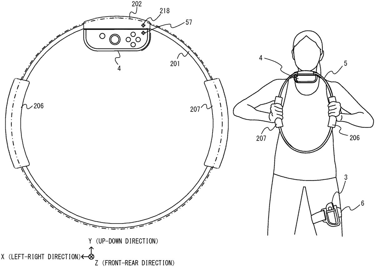
As shown inFIG. 9andFIG. 10, the ring-shaped extension apparatus5includes a ring-shaped portion201and a main portion202. The ring-shaped portion201has a ring shape. Note that in the present embodiment, the ring-shaped portion201includes an elastic member241and a base portion242(seeFIG. 18) and is formed in a ring shape. In the present embodiment, the ring-shaped portion201has a circular ring shape. Note that in other embodiments, the ring-shaped portion201may be of any shape, e.g., an elliptical ring shape. In the present embodiment, the diameter of the ring formed by the ring-shaped portion201is 30 [cm]. The ring-shaped portion201may be sized so that the user can hold a portion thereof one side with the left hand and another portion thereof on the other side with the right hand, the portions being symmetrical with each other with respect to the center of the ring. The size of the ring-shaped portion201may be determined in accordance with the body size and the age group of users contemplated, and the diameter may be 20 to 50 [cm], for example. In the present embodiment, the ring-shaped portion201is a band-shaped member having a predetermined width (e.g.,3to10[cm]) that is formed in a ring shape. Herein, the generally cylindrical space inside the ring-shaped portion201(generally, a cylindrical space whose bottom surfaces are the two circular areas R1and R2shown inFIG. 9) is referred to as “the space surrounded by the ring-shaped portion201”. Note that the circular area R1is a circular area whose circumference is defined by the edge of the elastic member241on the front side (i.e., the Z-axis negative direction side shown inFIG. 9), and the circular area R2is a circular area whose circumference is defined by the edge of the elastic member241on the rear side (i.e., the Z-axis positive direction side shown inFIG. 9). Although the details will be described later, as the band-shaped elastic member241is bent into a circular shape (strictly speaking, an incomplete circular shape), the ring-shaped portion201is formed into a ring shape that includes the elastic member241and the base portion242. As the elastic member241is bent into a circular shape, the opposing long sides of the band of the elastic member241are both formed into a circular shape that defines the circular area (R1, R2) therein. That is, the circumferences of the areas R1and R2are defined by the opposing long sides the band of the elastic member241bent as described above. In the present embodiment, a first plane that includes the circular area R1and a second plane that the circular area R2are both parallel to the XY plane, and the two areas R1and R2appear to coincide with each other as seen from the Z-axis direction. The cylindrical space is a space that is defined between the first plane and the second plane and within the circular areas R1and R2as seen from the direction (i.e., the Z-axis direction) perpendicular to the planes. At least a portion (the elastic member in the present embodiment) of the ring-shaped portion201is elastically deformable. Note that in the present embodiment, a member being “elastically deformable” means that the member is capable of being elastically deformed by such an amount that the deformation can be perceived by a human.
The right controller4can be attached to the main portion202. Note that a state where “the right controller4is attached to the main portion202” refers to a state where the right controller4is put on the main portion202. It can be said to be for example a state where the right controller4is integrally secured to the main portion202. Alternatively, it can be said to be for example a state where the right controller4and the main portion202cannot be separated from each other without a special operation or without applying a certain amount of load thereto. Note that to “secure” means that the right controller4and the main portion202do not basically move relative to each other, and there may be a slight movement therebetween.
The main portion202is provided on the ring-shaped portion201. Note that “the main portion202being provided on the ring-shaped portion201” means that the main portion202is secured to the ring-shaped portion201.
FIG. 11is a perspective view showing the vicinity of the main portion202of the ring-shaped extension apparatus5shown inFIG. 9. As shown inFIG. 11, the main portion202includes a rail portion211. The rail portion211is an example of an attachment portion to which the right controller4can be attached. In the present embodiment, the rail portion211slidably engages with the slider62of the right controller4. The rail portion211is an example of an extension apparatus-side engagement portion that engages with a game controller-side engagement portion (specifically, the slider62). It can be said that the rail portion211is an example of an extension apparatus-side slide portion that engages with a game controller-side slide portion.
The rail portion211is similar to the rail portion of the main body apparatus2in that it is slidably engageable with the slider of the controller. Therefore, the rail portion211may have a similar configuration to that of the rail portion of the main body apparatus2. By means of the rail portion211, the right controller4is attached to the main portion202. Note that although the details of the configuration of the rail portion211will be described later, the rail portion211is provided so as to extend in one direction (specifically, in the left-right direction to be described below).
FIG. 12is a diagram showing an example of a state where the right controller4is attached to the ring-shaped extension apparatus5. Herein, in the present embodiment, the up-down direction, the left-right direction and the front-rear direction of the ring-shaped extension apparatus5are defined as follows. First, in the present embodiment, the direction parallel to the direction (referred to as the “front view direction”) in which the ring formed by the ring-shaped portion201is viewed from front is the front-rear direction of the ring-shaped extension apparatus5(i.e., the Z-axis direction shown inFIG. 12). For example, “the direction in which the ring is viewed from front” is the direction from which the area of the shape represented by the outer edge of the ring appears largest. Where the ring is a circular ring, the “front view direction” can also be said to be the direction from which the ring appears circular.
As shown inFIG. 11, the rail portion211is provided on one side in the front-rear direction relative to the ring-shaped portion201. Specifically, in the present embodiment, as shown inFIG. 11, the rail portion211is provided on the Z-axis negative direction side relative to the ring-shaped portion201. Note that in the present embodiment, this side is denoted as the front side (in other words, the front near side) of the ring-shaped extension apparatus5, and the opposite side thereto is denoted as the rear side (in other words, the back side) of the ring-shaped extension apparatus5.
The rail portion211of the main portion202is provided so as to extend in a direction that is substantially perpendicular to the front-rear direction. In the present embodiment, the direction that is perpendicular to the front-rear direction and substantially parallel to the direction in which the rail portion211extends is denoted as the left-right direction of the ring-shaped extension apparatus5(i.e., the X-axis direction shown inFIG. 12).
As used herein, “substantially (in a certain state)” means to include both cases where the certain state is achieved in a strict sense and cases where the certain state is generally achieved. For example, “the left-right direction is substantially parallel to the rail portion211” means to include both cases where the left-right direction is parallel to the rail portion211in a strict sense and cases where they are generally parallel to each other though not strictly parallel to each other.
As shown inFIG. 11, the rail portion211is shaped so that one end thereof in the left-right direction is open with the other end thereof being closed. In the present embodiment, the side of the first end that is open is denoted as the right side of the ring-shaped extension apparatus5, and the side of the other end as the left side of the ring-shaped extension apparatus5. That is, the direction (i.e., the X-axis positive direction shown inFIG. 12) in which the right controller4is inserted into the rail portion211of the main portion202, as the ring-shaped extension apparatus5is viewed from the front side, is the left direction of the ring-shaped extension apparatus5, and the opposite direction thereto is the right direction of the ring-shaped extension apparatus5(seeFIG. 12).
Moreover, in the present embodiment, the direction that is perpendicular to the front-rear direction and the left-right direction is denoted as the up-down direction of the ring-shaped extension apparatus5(i.e., the Y-axis direction shown inFIG. 12). The direction from the main portion202toward the center of the ring-shaped portion201, as the ring-shaped extension apparatus5is viewed from the front side, is denoted as the down direction of the ring-shaped extension apparatus5(i.e., the Y-axis negative direction shown inFIG. 12), and the opposite direction thereto as the up direction of the ring-shaped extension apparatus5.
Where directions of the ring-shaped extension apparatus5are defined as described above, it can be said that the main portion202is provided on the upper end portion of the ring-shaped portion201. Note that in the present embodiment, where directions of the ring-shaped extension apparatus5are defined as described above, the up direction is equal to the direction (i.e., the x-axis positive direction inFIG. 6) in which the shaft portion of the analog stick52is inclined for giving an up instruction to the analog stick52of the right controller4as attached to the ring-shaped extension apparatus5.
[1-2-1. Main Portion]
As shown inFIG. 11, the main portion202includes a housing212. The housing212is secured to the ring-shaped portion201using screws, for example (the details will be described later). In the present embodiment, the housing212is secured to the ring-shaped portion201so as to cover a portion of the ring-shaped portion201(specifically, a portion of the ring-shaped portion201near the upper end). As shown inFIG. 11, the housing212is shaped so as to protrude forward relative to the ring-shaped portion201. Note that in the present embodiment, the housing212is shaped so as to also protrude rearward relative to the ring-shaped portion201. In the present embodiment, the amount by which the housing212protrudes forward relative to the ring-shaped portion201is greater than the amount by which the housing212protrudes rearward relative to the ring-shaped portion201.
As shown inFIG. 11, the rail portion211is provided on the housing212. The rail portion211has a groove extending in the left-right direction (in other words, the slide direction). As shown inFIG. 11, the groove of the rail portion211is open at the right end thereof (i.e., the end thereof on the X-axis negative direction side).
The groove of the rail portion211is shaped so that the groove is slidably engageable with the slider62of the right controller4. Specifically, the cross-sectional shape of the slider62of the right controller4along a section perpendicular to the slide direction (i.e., the y-axis direction shown inFIG. 6) is generally a T-letter shape. The slider62has a top surface on one side that is away from the side surface of the right controller4(i.e., the surface on the x-axis positive direction side shown inFIG. 6), and has protruding portions that are protruding on opposite sides of the direction (i.e., the z-axis direction shown inFIG. 6) parallel to the top surface as viewed from the slide direction. On the other hand, the rail portion211has two opposing portions215that are opposing the bottom surface214of the groove and are protruding inward from the side surfaces of the groove, as viewed from the direction perpendicular to the slide direction (i.e., the X-axis direction shown inFIG. 11). The slider62is inserted into the rail member211so that the protruding portions of the slider62slide into between the bottom surface214and the opposing portions215of the rail portion211, thereby engaging the slider62and the rail member211with each other. Thus, as the slider62is inserted into the rail member211in a predetermined straight direction (i.e., the slide direction), the rail member211engages with the slider62so that the slider62is slidable against the rail member211in the straight direction. The slider62in engagement with the rail member211is restricted so as not come off the rail member211in a direction that is perpendicular to the slide direction (or a direction that is different from the slide direction).
A stopper portion213for stopping the slide movement of the slider62, which has been inserted from the right end of the rail portion211, is provided at the left end of the rail portion211(seeFIG. 11). The stopper portion213is a part of the opposing portion215. The stopper portion213is provided at the left end of the groove of the rail portion211. Herein, across the groove excluding the left end thereof, the opposing portion215protrudes by a predetermined length from the side surface of the groove. At the left end portion of the groove, the opposing portion215protrudes by a greater length than the predetermined length. In the present embodiment, the part of the opposing portion215that is protruding by a greater length than the predetermined length is referred to as the stopper portion213(seeFIG. 11). Note that the dotted lines inFIG. 11are drawn for ease of understanding of the position of the stopper portion213, and the dotted lines are not actually drawn on the rail portion211. Thus, the slider62comes into contact with the stopper portion213as the slider62is inserted from the right end of the rail portion211and is slid toward the left end of the rail portion211. Note that the lower end portion (i.e., the end portion on the y-axis negative direction side shown inFIG. 6) of the slider62is shaped so that the protruding portion thereof on the side that is away from the side surface of the right controller4is protruding relative to the base portion on the side that is close to the side surface of the right controller4(i.e., the side that is in contact with the side surface) as viewed from the direction (i.e., the z-axis direction shown inFIG. 6) that is parallel to the top surface and perpendicular to the slide direction (seeFIG. 6). When the slider62is slid in the insertion direction (i.e., the direction from the right end to the left end of the rail portion211), the stopper portion213comes into contact with the base portion. Note that with the stopper portion213in contact with the base portion, the protruding portion may be or may not be in contact with the wall surface on the left side of the groove of the rail portion211(i.e., the far side where the slider62is inserted from the right end of the groove). As described above, the slide movement of the slider62is stopped as the slider62comes into contact with the stopper portion213. Note that in other embodiments, when the slider62is slid in the insertion direction, the slide movement of the slider62may be stopped as the protruding portion comes into contact with the wall surface on the left side of the groove of the rail portion211before the stopper portion213comes into contact with the base portion.
In the present embodiment, the right controller4includes a latch portion63(seeFIG. 6). The latch portion63is provided so as to protrude sideways (i.e., the z-axis positive direction shown inFIG. 6) from the slider62. While the latch portion63is allowed to move into the slider62, the latch portion63is urged (e.g., by means of a spring) into the position described above in which the latch portion63is protruding sideways. As shown inFIG. 11, the opposing portion215of the rail portion211is provided with a notch219. The notch219is provided at a position that opposes the latch portion63in a state where the slider62is inserted to the far end of the rail portion211(specifically, a state where the slider62is in contact with the stopper portion213. Note that the slider62does not need to be strictly in contact with the stopper portion213but there may be a slight gap between the slider62and the stopper portion213). Therefore, with the slider62inserted to the far end of the rail portion211, the latch portion63snaps into the notch219. That is, the latch portion63engages with the notch219. With the latch portion63in engagement with the notch219, the slide movement of the slider62is restricted in the direction in which the slider62is removed from the rail portion211(i.e., the direction in which the slider62moves away from the stopper portion213). Therefore, with the latch portion63in engagement with the notch219, the slider62does not come off the rail portion211even if a certain force is applied. As described above, as the latch portion63engages with the notch219while the rail portion211is in engagement with the slider62, the right controller4is attached to the main portion202.
Note that with the latch portion63in engagement with the notch219, the slide movement of the slider62against the rail portion211is restricted by the latch portion63both for the insertion direction and for the reverse direction of the insertion direction. Therefore, in the state described above, the slide movement in the insertion direction can be said to be restricted by the stopper portion213or can be said to be restricted by the latch portion63. Note that in other embodiments, the slide movement in the insertion direction may be restricted by either one of the stopper portion213and the latch portion63.
Note that although not shown in the figures, in the present embodiment, the upper surface (i.e., the surface on the y-axis positive direction side shown inFIG. 6) of the latch portion63is substantially perpendicular to the slide direction, whereas the lower surface of the latch portion63is a sloped surface that is inclined relative to the slide direction. Note that the lower surface is sloped so that when the slider62is inserted into the rail portion211and moved in the insertion direction, the latch portion63is unlikely to interfere with the opposing portion215, allowing for smooth slide movement. Since the upper and lower surfaces of the latch portion63are configured as described above, the movement of the slider62in the reverse direction of the insertion direction is restricted with a relatively strong force because the upper surface is in contact with the notch219of the opposing portion215while the latch portion63is in engagement with the notch219. On the other hand, the movement of the slider62in the insertion direction is restricted with a relatively weak force because the sloped surface is in contact with the notch219of the opposing portion215. Note however that in other embodiments, the lower surface of the latch portion63may be substantially perpendicular to the slide direction, as is the upper surface of the latch portion63, so as to increase the force with which to restrict the slide movement of the latch portion63in the insertion direction.
As described above, in the present embodiment, the “state where the right controller4is attached to the main portion202” refers to a state where the respective engagement portions thereof (e.g., the rail portion211and the slider62) are in engagement with each other and where the slide movement is restricted. Thus, the right controller4is put on the main portion202. In the present embodiment, the engagement of the latch portion63with the notch219is released as the latch portion63is retracted into the slider62(by operating a release button69to be described below). This releases the state where the right controller4is attached to, i.e., put on, the main portion202. Then, the right controller4is removed from the main portion202when the slider62is slid in the direction opposite to the insertion direction and the engagement between the slider62and the rail portion211is released.
Note that while the slide movement is restricted by the latch portion63and the notch219in the present embodiment, there is no limitation on the method for restricting the slide movement. For example, in other embodiments, the rail portion211may include a portion that comes into contact with the slider62so as to press the slider62with a force that includes a component perpendicular to the slide direction when the slider62is inserted to the far end of the rail portion211, thereby restricting the slide movement by means of the frictional force between this portion and the slider62.
Thus, when the right controller4is put on the ring-shaped extension apparatus5, the user first inserts the slider62of the right controller4into the rail portion211from the right end of the rail portion211. Then, the user slides the inserted slider62toward the left end of the rail portion211to the far end thereof, thereby engaging the latch portion63with the notch219, achieving the state where the right controller4is attached to the main portion202. As described above, the user can put the right controller4on the ring-shaped extension apparatus5.
Note that the right controller4includes the release button69that can be pressed (seeFIG. 6). In response to the release button69being pressed, the latch portion63moves into the slider62, achieving the state where the latch portion63no longer (or substantially no longer) protrudes relative to the slider62. Therefore, when the release button69is pressed in the state where the right controller4is attached to the main portion202of the ring-shaped extension apparatus5, the latch portion63is no longer (or is substantially no longer) in engagement with the notch219. Thus, in the state where the right controller4is attached to the main portion202of the ring-shaped extension apparatus5, the user can easily remove the right controller4from the ring-shaped extension apparatus5by pressing the release button69.
As described above, the housing212is provided so as to protrude forward relative to the ring-shaped portion201. Specifically, as shown inFIG. 11, an inner side surface216of the housing212(i.e., the surface that faces the central axis of the ring formed by the ring-shaped portion201) has a portion that protrudes more forward than it does rearward relative to the ring-shaped portion201. The rail portion211is provided on this portion of the inner side surface216. Thus, the rail portion211is provided on the outer side of the space surrounded by the ring-shaped portion201. Note that the region “on the outer side of the space surrounded by the ring-shaped portion201” at least includes a region that is forward of the front end of the ring-shaped portion201with respect to the front view direction, and a region that is rearward of the rear end of the ring-shaped portion201with respect to the front view direction. In the present embodiment, the rail portion211is provided in such a region. More specifically, as the ring formed by the ring-shaped portion201is viewed from the front side is viewed from the front side, the rail portion211is on one side in the front view direction relative to the hole of the housing212(i.e., the hole through which the ring-shaped portion201passes). Note that it can also be said that the rail portion211is provided in such an orientation that the slide direction thereof is substantially perpendicular to the front view direction and is provided at a position that is shifted off the ring-shaped portion201in the front view direction. Thus, the rail portion211is provided at a position that is away from the ring-shaped portion201in the front view direction (specifically, on the near side relative to the ring-shaped portion201as viewed from the front view direction).
According to the description above, the ring-shaped portion201, which is deformed by an operation of the user, is less likely to contact the rail portion211. Thus, it is possible to reduce the possibility that the ring-shaped portion201contacts the rail portion211, thereby detaching the right controller4from the ring-shaped extension apparatus5. While one may consider increasing the diameter of the ring-shaped portion201so that the ring-shaped portion201, when deformed, is less likely to contact the rail portion211, the need for increasing the size of the ring-shaped portion201is reduced in the present embodiment (because the rail portion211is shifted in the front view direction relative to the ring-shaped portion201so that they are less likely to contact each other). When the user puts the right controller4on the ring-shaped extension apparatus5by inserting the slider62of the right controller4into the rail portion211, the right controller4is unlikely to contact the ring-shaped portion201. This makes it easier for the user to perform the operation of putting the right controller4on the ring-shaped extension apparatus5.
In the present embodiment, the rail portion211is provided outside the area through which the ring-shaped portion201passes when the ring-shaped portion201is deformed so as to elongate in the up-down direction (i.e., the direction parallel to the straight line that connects together the center of the rail portion211and the center of the ring formed by the ring-shaped portion201) and shrink in the left-right direction. Thus, it is possible to achieve the state where the rail portion211is unlikely to contact the ring-shaped portion201.
In the present embodiment, the slide direction of the rail portion211is perpendicular to the front view direction. Thus, the rail portion211can be arranged in a compact arrangement so as not to protrude in the front view direction. In the present embodiment, the rail portion211is provided so that the straight line that connects together the central portion of the rail portion211in the slide direction and the center of the ring is perpendicular to the slide direction as the ring formed by the ring-shaped portion201is viewed from the front side. Thus, the rail portion211can be arranged close to the ring-shaped portion201(in the present embodiment, the rail portion211is arranged in the vicinity of the inner circumference of the ring-shaped portion201as viewed from the front view direction as shown inFIG. 12) while maintaining the state where the rail portion211is unlikely to contact the ring-shaped portion201. Therefore, the ring-shaped extension apparatus5as a whole can be made compact.
As shown inFIG. 11, the rail portion211is provided on one side of the main portion202that is closer to the central axis of the ring formed by the ring-shaped portion201(i.e., located on the side of the central axis of the ring relative to the center of the main portion202). Specifically, the rail portion211is provided on the surface of the main portion202that is facing the center of the ring (specifically, the inner side surface216) so that the right controller4can be attached facing the inner side of the ring-shaped portion201. The rail portion211(specifically, the bottom surface214of the rail portion211) faces toward the space surrounded by the ring-shaped portion201, i.e., toward the central axis of the ring formed by the ring-shaped portion201. Note that “the central axis of the ring” is an axis that passes through the center of the ring as viewed from the front side and extends in parallel to the front view direction of the ring. Moreover, “the rail portion211facing toward the central axis of the ring” is not limited to embodiments where the normal to the bottom surface of the rail portion211strictly passes through the central axis of the ring.
As the ring formed by the ring-shaped portion201is viewed from the front side, the rail portion211is provided at a position on the inner side relative to the outer edge of the ring (see the one-dot-chain line shown inFIG. 12. Note however that the one-dot-chain line is drawn inFIG. 12to be slightly on the outer side of the outer edge of the ring for the sake of illustration). Note that in the present embodiment, since the right controller4is attached to the main portion202so that the bottom surface of the rail portion211faces toward the center of the ring and the left side surface of the right controller4is parallel to the bottom surface of the rail portion211, and the primary surface of the right controller4is perpendicular to the left side surface, the front view direction is perpendicular to the primary surface. Therefore, it can be said that “as the ring formed by the ring-shaped portion is viewed from the front side” in the present embodiment means as the ring is viewed from the direction perpendicular to the primary surface of the right controller4attached to the main portion202. As described above, the main portion202is attached to the right controller4so as to be located on the inner side relative to the outer edge of the ring as the ring formed by the ring-shaped portion201is viewed from the front side. Note that it can also be said that the main portion202is attached to the right controller4so that the right controller4is located on the side of the center of the ring formed by the ring-shaped portion201relative to the main portion202. Note that “on the inner side relative to the outer edge of the ring formed by the ring-shaped portion201” refers to an area that can be seen on the inner side of the outer edge of the ring as viewed from the front view direction. Therefore, the rail portion211may be at a different location from the ring-shaped portion201with respect to the front view direction.
According to the configuration where the rail portion211faces toward the central axis of the ring or the configuration where the rail portion211is located on the inner side relative to the outer edge of the ring as described above, it is possible to reduce the possibility that the right controller4contacts other objects when the user uses the ring-shaped extension apparatus5with the right controller4attached thereto. Therefore, it is possible to reduce the possibility that the right controller4contacts other objects so that the right controller4comes off the ring-shaped extension apparatus5or is damaged.
Note that in other embodiments, at least a portion of the rail portion211may be provided at a position on the inner side relative to the outer edge of the ring formed by the ring-shaped portion201. That is, the right controller4may be attached to the main portion202so that at least a portion of the right controller4is at a position on the inner side relative to the outer edge of the ring formed by the ring-shaped portion201. This also makes it possible to reduce the possibility that the right controller4attached to the ring-shaped extension apparatus5contacts other objects.
In the present embodiment, the primary surface of the right controller4attached to the main portion202faces the front side as the ring formed by the ring-shaped portion201is viewed from the front side (seeFIG. 12). The direction in which the analog stick52sticks out is the direction in which a portion of the main portion202where the rail portion211is provided (i.e., a portion that protrudes forward) protrudes relative to the ring-shaped portion201. Therefore, in the present embodiment, when the user holds the ring-shaped extension apparatus5while facing the ring-shaped extension apparatus5, the primary surface of the right controller4attached to the ring-shaped extension apparatus5faces the user. Thus, it is easy for the user to operate the operation sections provided on the primary surface of the right controller4(e.g., the analog stick52and the buttons53to56) even when the right controller4is attached to the ring-shaped extension apparatus5.
As shown inFIG. 12, the housing212has a marking218thereon that is located so as to be next to a plus button57of the right controller4when attached to the main portion202. Specifically, the marking218is located so as to come gradually closer to the plus button57as the right controller4is slid in the insertion direction while in engagement with the rail portion211. Moreover, the marking218is located so as to be perpendicular to the slide direction with respect to the plus button57in the state where the right controller4is attached to the main portion202. Moreover, the marking218is located so as to be in symmetry with the plus button57with respect to the boundary between the primary surface of the right controller4and the housing212(herein, the gap between the primary surface of the right controller4and the housing212). That is, the length of the perpendicular drawn from the boundary to the position of the marking218is generally equal to the length of the perpendicular drawn from the boundary to the position of the plus button57. With the right controller4attached to the main portion202, the distance between the marking218and the plus button57is shorter than the distance between the operation section (herein, the X button55) of the right controller4that is closest to the plus button57and the plus button57. With the right controller4attached to the main portion202, an operation section, among all the operation sections of the right controller4, that is located closest to the marking218is the plus button57.
As shown inFIG. 12, the marking218represents the plus button57. Note that the marking218may be a (solid) part provided on the housing212or may be a pattern drawn on the housing212. While the marking218has the same shape as the plus button57in the present embodiment, the marking218may have any shape that represents the plus button57. Note that “the shape of the marking” means that it may be a solid shape whose outer shape represents the object or may be a planar shape whose pattern represents the object. Instead of directly representing the plus button57, the marking218may have a shape that is reminiscent of the plus button57or may have a shape that is associated with the plus button57(excluding a shape that represents a minus sign). With the marking218, the user can realize that the right controller4having the plus button57thereon, rather than the left controller3having the minus button47thereon, should be put on the ring-shaped extension apparatus5. Based on the position of the marking218, the user can realize that when the right controller4is put on the ring-shaped extension apparatus5, the user should insert the right controller4into the rail portion211up to a position where the plus button57and the marking218are aligned together. Note that the marking218may have a shape such as an arrow shape, for example, instead of a shape relating to the plus button57. Thus, with the marking218, it is easier for the user to perform the operation of putting the right controller4on the ring-shaped extension apparatus5. Note that the shape and the position of the marking218are not limited to those described above, but any suitable changes may be made thereto as long as the user can realize that the right controller4, rather than the left controller3, should be put on the ring-shaped extension apparatus5, and the user can realize how far into the rail portion211the right controller4should be inserted when putting the right controller4on the ring-shaped extension apparatus5.
The ring-shaped extension apparatus5includes a terminal (a terminal294shown inFIG. 26) for electrical connection with the right controller4. The terminal294is provided at a position along the rail portion211that corresponds to the terminal64of the right controller4attached to the ring-shaped extension apparatus5. The terminal64of the right controller4is provided on a surface that opposes the housing51near the lower end (i.e., the end portion in the insertion direction) of the slider62(seeFIG. 6). Thus, the terminal294is provided on the reverse side surface of the stopper portion213(i.e., a surface that opposes the bottom surface214of the rail portion211). Therefore, when the right controller4is attached to the ring-shaped extension apparatus5(i.e., when the latch portion63of the right controller4engages with the notch219of the rail portion211while the slider62of the right controller4is in engagement with the rail portion211), the terminal294of the ring-shaped extension apparatus5and the terminal64of the right controller4come into contact with each other. Thus, the terminal294of the ring-shaped extension apparatus5and the terminal64of the right controller4are electrically connected to each other. Note that in the present embodiment, the terminal294is provided on the side (i.e., the left side) of the rail portion211that is opposite to the side from which the right controller4is inserted. Thus, when the right controller4is attached to the rail portion211, it is possible to reduce the frequency the terminal294contacts the right controller4, and it is possible to reduce the possibility that the terminal294is damaged.
FIG. 13andFIG. 14are exploded perspective views of the main portion shown inFIG. 11.FIG. 13is an exploded perspective view of the main portion202as viewed from the inner side of the ring formed by the ring-shaped portion201(specifically, the Y-axis negative direction side), andFIG. 14is an exploded perspective view of the main portion202as viewed from the outer side of the ring formed by the ring-shaped portion201(specifically, the Y-axis positive direction side).
As shown inFIG. 13andFIG. 14, in the present embodiment, the housing212includes an inner housing221and an outer housing222. The inner housing221is generally arranged on the inner side of the ring formed by the ring-shaped portion201. The outer housing222is generally arranged on the outer side of the ring formed by the ring-shaped portion201. The inner housing221and the outer housing222are secured to each other using screws, for example. Note that in the present embodiment, there is no limitation on the method for securing two members together (i.e., so that one member does not come off the other member), and it may be a method for connecting together two members by fastening using screws, or the like, a method for bonding together two members using an adhesive, or a method for fitting one member to the other member.
As shown inFIG. 13andFIG. 14, the ring-shaped portion201is secured to the housing212while being sandwiched between the inner housing221and the outer housing222. In the present embodiment, as the inner housing221and the base portion of the ring-shaped portion201are fastened together using screws, thereby securing the ring-shaped portion201to the inner housing221. The ring-shaped portion201is secured to the housing212while passing through a hole that is produced when the inner housing221and the outer housing222are secured together. Thus, a portion of the ring-shaped portion201(specifically, a portion including the base portion to be described below) is covered by the housing212.
As shown inFIG. 13, the rail portion211is secured to the inner housing221using screws, for example. The inner housing221has a retracted portion217that is retracted from the inner side surface216, and the rail portion211is secured to the retracted portion217. In the present embodiment, the depth of the retracted portion217is slightly greater than the thickness of the rail portion211. Therefore, with the rail portion211secured to the retracted portion217of the inner housing221, the stopper portion213and the opposing portion215of the rail portion211are located slightly retracted relative to the inner side surface216.
As described above, in the present embodiment, the rail portion211is located retracted relative to the surface (e.g., the inner side surface216) of the housing212. Thus, with the right controller4attached to the ring-shaped extension apparatus5, the inner side surface216of the housing212is in contact with the right controller4to apply a force pressing against the right controller4. This reduces the looseness between the ring-shaped extension apparatus5and the right controller4.
In the present embodiment, the rail portion211is provided on the housing212with a portion of the rail portion211exposed to the outside of the housing212so that the slider62can be inserted into the rail portion211. As shown inFIG. 13andFIG. 14, as for the length of the rail portion211in the slide direction (i.e., the X-axis direction), the length (L1shown inFIG. 11) of the non-protruding portion of the housing212that covers the ring-shaped portion201is shorter than the length (L2shown inFIG. 11) of the protruding portion of the housing212where the rail portion211is provided. Thus, according to the present embodiment, it is possible to securely protect the rail portion211by the housing212, and it is possible to make the housing212compact by relatively reducing the area where the housing212covers the ring-shaped portion201. When designing the shape of the housing212, first, the length of the protruding portion is determined based on the length of the slider62of the right controller4. With the length of the protruding portion having been determined, in order to make the outer shape of the housing212simple, one may consider making the length of the housing212in the slide direction constant at the length of the protruding portion of the housing212, thereby making flat the surfaces of the housing212on opposite sides in the slide direction. However, if the first portion where the housing212covers the ring-shaped portion201becomes longer in that direction, the ring-shaped portion201may be more likely to contact the housing212when the ring-shaped portion201is deformed, and the load to be applied to the housing212as the ring-shaped portion201contacts the housing212may increase. In contrast, according to the present embodiment, by making the non-protruding portion compact, the ring-shaped portion201is less likely to contact the housing212and it is possible to reduce the load applied to the housing212when contacted by the ring-shaped portion201, as compared with the case where the housing212has a constant length in the slide direction.
As shown inFIG. 13andFIG. 14, the ring-shaped extension apparatus5includes a substrate223. A circuit that functions as a processing section293, a signal conversion section292and a power conversion section295(seeFIG. 26) to be described below is provided on the substrate223. The substrate223is provided inside the housing212, and is fastened to the housing212using screws, for example. In the present embodiment, the protruding portion includes the substrate223. Specifically, the substrate223is provided inside the protruding portion. Note that although not shown in the figures, the circuit on the substrate223is electrically connected to the terminal294described above and is electrically connected to a strain gauge to be described below.
As shown inFIG. 13andFIG. 14, the main portion202includes a lightguide portion224and a holder225. The holder225holds the lightguide portion224inside the housing212. That is, in the present embodiment, the holder225for holding the lightguide portion224is secured to the housing212.
As described above, the right controller4includes the indicator LEDs67on the engaging surface of the slider62(seeFIG. 6). With the right controller4attached to the ring-shaped extension apparatus5, the engaging surface of the slider62opposes the bottom surface of the rail portion211and is no longer exposed. Therefore, in the present embodiment, the lightguide portion224is provided so as to allow the user to see the light emitted from the indicator LEDs67from outside the housing212even in the state described above.
The lightguide portion224includes the same number of lightguides as the number of the indicator LEDs67(herein, four). One end of each lightguide is the light-receiving surface, and the other end thereof is the light-exiting surface. The lightguides are transparent members made of a resin, or the like, for example. Note that the lightguides are each any component that has the function of guiding light from the light-receiving surface to the light-exiting surface. The lightguide may have any shape such that the light-receiving surface is located in the vicinity of the light-receiving port to be described later and the light-exiting surface is located in the vicinity of the light-exiting port to be described later.
As shown inFIG. 13, a light-receiving port H1is provided on the retracted portion217of the inner housing221, and a light-receiving port H2is provided on the bottom surface214of the rail portion211. The light-receiving ports H1and H2are located so as to substantially oppose the position of the indicator LEDs67of the right controller4attached to the ring-shaped extension apparatus5. Specifically, the position of the light-receiving ports H1and H2overlaps with the position of the indicator LEDs67for the left-right direction (i.e., the X-axis direction) and the front-rear direction (i.e., the Z-axis direction) of the ring-shaped extension apparatus5. The holder225holds the lightguide portion224at such a position that the light-receiving surfaces of the lightguide portion224are exposed through the light-receiving ports H1and H2.
As shown inFIG. 14, the outer housing222includes light-exiting ports H3. In the present embodiment, the outer housing222includes the same number, i.e., four, of light-exiting ports H3as the number of the indicator LEDs67. The holder225holds the lightguide portion224at such a position that the light-exiting surfaces of the lightguide portion224are exposed respectively through the light-exiting ports H3. Therefore, when light from the indicator LEDs67of the right controller4enters the light-receiving port H2, light is guided through the lightguide portion224to exit through the light-exiting ports H3.
Thus, the lightguide portion224guides the light, which is from the indicator LEDs67of the right controller4attached to the ring-shaped extension apparatus5and received by the light-receiving port H2provided on a predetermined surface (specifically, the bottom surface214) of the rail portion211, to the light-exiting port H3provided on another surface of the main portion202that is different from the predetermined surface of the rail portion211. Then, based on the light from the light-exiting port H3, the user can check the light emission of the indicator LEDs67, even when the right controller4is attached to the ring-shaped extension apparatus5. Information that is conveyed by the indicator LEDs67of the right controller4can be presented to the user with a simple configuration using the lightguide portion224.
Note that in the present embodiment, the light-exiting ports H3are provided at positions that can be seen from the front side and from the upper side of the ring-shaped extension apparatus5(seeFIG. 10). Therefore, in the present embodiment, the user can see the light from the light-exiting ports H3not only when the ring-shaped extension apparatus5is used at a relatively high position with the front side the ring-shaped extension apparatus5facing toward the front side (seeFIG. 15), but also when the ring-shaped extension apparatus5is used at a relatively low position, and when the ring-shaped extension apparatus5is not held by the user and is put down where the user sees the ring-shaped extension apparatus5from outside the ring formed by the ring-shaped portion201. That is, the light-exiting ports H3can be arranged at such positions that it is easy for the user to see the light from the light-exiting ports H3.
Note that in other embodiments, there is no limitation on the positions of the light-exiting ports H3, and the light-exiting ports H3may be provided at any positions where the light-exiting ports H3can be seen from outside the housing212. For example, the light-exiting ports H3may be provided at any positions on the outer housing222.
[1-2-2. Grip Cover]
As shown inFIG. 10andFIG. 12, the ring-shaped extension apparatus5includes grip covers206and207. The grip covers206and207are components to be held by the user. In the present embodiment, with the provision of the grip covers206and207, it is easier for the user to hold the ring-shaped extension apparatus5. The details of the grip covers206and207will now be described.
As shown inFIG. 10andFIG. 12, in the present embodiment, two grip covers206and207are provided on the ring-shaped portion201. In the present embodiment, the grip covers206and207can be removed from the ring-shaped portion201. The grip covers206and207are put on the grip portions of the ring-shaped portion201. Herein, a grip portion is a portion of the ring-shaped portion201to be held by the user. In the present embodiment, a portion of the ring-shaped portion201near the right end thereof and a portion of the ring-shaped portion201near the left end thereof are the grip portions. That is, it can be said that when the main portion202is located at the central angle of 0° with respect to the center of the ring-shaped portion201, the grip portions are provided at the position of +90° and at the position of −90°. Hereinafter, the grip portion near the right end of the ring-shaped portion201will be referred to as the right grip portion, and the grip portion near the left end of the ring-shaped portion201will be referred to as the left grip portion. Although the details will be described later, each grip portion is provided with an element (a fourth touch fastener233to be described below) that allows the grip cover206or207to be put on. Where the grip cover206or207is removable from the ring-shaped portion201as in the present embodiment, the portion where the element that allows the grip cover206or207to be put on is provided can be said to be the grip portion.
Note that the grip portions may have any configuration such that the grip portions can be recognized distinguished from the other portions of the ring-shaped portion201. For example, when portions of the ring-shaped portion201(specifically, a portion near the left end and a portion near the right end of the ring-shaped portion201) are of a different color and/or a different pattern from the other portions, they can be said to be grip portions (as they serve to allow the user to realize that they are the portions to be held for performing operations). When portions of the ring-shaped portion201(specifically, a portion near the left end and a portion near the right end of the ring-shaped portion201) are formed to be thicker than the other portions, they can be said to be grip portions (as they serve to allow the user to realize that they are the portions to be held for performing operations). For example, when similar members to the grip covers are non-removably secured to the ring-shaped portion201, those members can be said to be grip portions. As described above, with the grip portions, the ring-shaped extension apparatus5allows the user to perform operations while holding appropriate positions thereof.
Note that in the present embodiment, the user holds the grip covers206and207, which are put on the grip portions of the ring-shaped portion201, thereby indirectly holding the grip portions. In contrast, in other embodiments, the ring-shaped extension apparatus5may include no grip covers, in which case the user can directly hold the grip portions of the ring-shaped portion201. That is, the grip portions may be portions to be directly or indirectly held by the user.
In the present embodiment, the left grip cover206is provided on the left grip portion near the left end of the ring-shaped portion201, and the right grip cover207is provided on the right grip portion near the right end of the ring-shaped portion201. Thus, in the present embodiment, the grip portions are provided at two locations, left and right, of the ring-shaped portion201assuming that the user will be holding the two grip portions with two hands, respectively. Note that there is no limitation on the number of grip portions, and the grip portions may be provided at three or more locations, or at only one location, depending on the operation method or methods contemplated. Depending on the content of the game (or the content of the fitness exercise operation to be performed by the user in the game), only a particular one or particular ones of a plurality of grip portions may be held by one hand or both hands. In other embodiments, there may be no grip portions that can be recognized distinguished from the other portions of the ring-shaped portion201.
FIG. 15is a diagram showing an example of how the user uses the extension apparatus. As shown inFIG. 15, when using the ring-shaped extension apparatus5, the user can hold the left grip cover206put on the left grip portion with the left hand and hold the right grip cover207put on the right grip portion with the right hand. Note that although the details will be described later, the user can use the ring-shaped extension apparatus5in a different manner from that shown inFIG. 15.
In the present embodiment, the two grip portions can provided at positions on the ring-shaped portion201that are in symmetry with each other with respect to the center of the circular ring (which may also be an elliptical ring) of the ring-shaped portion201(seeFIG. 12). This allows the user to hold the ring-shaped portion201at such positions that it is easier for the user to apply a force on the ring-shaped portion201, and it is possible to provide an input apparatus that is easy to operate.
In the present embodiment, two grip portions are provided in parallel to the left-right direction. Therefore, the rail portion211of the main portion202is provided in such an orientation that the direction from one of the two grip portions to the other is substantially parallel to the slide direction (of the rail portion211). It is assumed that when using the ring-shaped extension apparatus5, the user holds the ring-shaped extension apparatus5so that the two grip portions are arranged horizontal with each other (seeFIG. 15). Therefore, in the state where the ring-shaped extension apparatus5is held as described above, the user can put the right controller4on the ring-shaped extension apparatus5by horizontally moving and inserting the right controller4into the rail portion211. That is, according to the present embodiment, it is easier for the user to put the right controller4on the ring-shaped extension apparatus5while holding the ring-shaped extension apparatus5.
Note that in the present embodiment, where the up direction is defined as the direction in which the shaft portion of the analog stick52is tilted to give an upward instruction to the analog stick52of the right controller4attached to the ring-shaped extension apparatus5, the main portion202is provided at a position on the ring-shaped portion201that is on the upper side relative to the center of the ring formed by the ring-shaped portion201(seeFIG. 12). Then, it is assumed that the user uses the ring-shaped extension apparatus5in such an orientation that the main portion202is located on the upper side (seeFIG. 15). Therefore, assuming that the user uses the ring-shaped extension apparatus5in such an orientation, even if the user inadvertently drops the ring-shaped extension apparatus5during use, the shock is less transmitted to the right controller4, and it is possible to reduce the possibility that the right controller4comes off the ring-shaped extension apparatus5.
Note that in the present embodiment, since the ring-shaped portion201is elastically deformable, even if the user inadvertently drops the ring-shaped extension apparatus5during use, the shock is absorbed by the ring-shaped portion201. Therefore, even in such a case as described above, the possibility is low for the right controller4to come off the ring-shaped extension apparatus5.
While the user is using the ring-shaped extension apparatus5, the user may switch grip from holding two grip portions, and operate the right controller4while letting go of one hand from the grip portion. In such a case, in the present embodiment, since the main portion202is provided on the upper side relative to the grip portions, it is possible to arrange the right controller4at such a position that it is easy to operate the right controller4.
FIG. 16is a diagram showing an example of the left grip cover206.FIG. 17is a diagram illustrating a case where the left grip cover206is put on the left grip portion of the ring-shaped portion201. Note that the grip cover will be described with reference to the left grip cover206as an example, while omitting the detailed description of the right grip cover207, which has a similar configuration to the left grip cover206.
The left grip cover206has a flat shape and is made of a fabric. As shown inFIG. 16, the left grip cover206has a generally quadrangular shape. As shown inFIG. 17the left grip cover206is put on the ring-shaped portion201in a tubular shape (in other words, the left grip cover206is wound around the ring-shaped portion201). The left grip cover206may be of any material such that the left grip cover206can be rolled into a tubular shape by securing one end thereof to the other end thereof. The left grip cover206may have a shock absorbing material, such as foam, inside so that it is easier for the user to hold.
FIG. 16shows the inner side surface the left grip cover206. Note that the inner side surface of the left grip cover206is a surface to be on the inner side when the left grip cover206is put on around the ring-shaped portion201. As shown inFIG. 16, a first touch fastener231is provided at the end portion on one side of the inner side surface of the left grip cover206, and a second touch fastener232is provided at the end portion on the other side. Note that the “end portion”, as used herein, refers to the tip in a strict sense and to a portion around the tip. Although not shown in the figures, a third touch fastener is provided on the area of the outer side surface of the left grip cover206that is on the reverse side of the first touch fastener231. The second touch fastener232and the third touch fastener can be attached to and detached from each other. For example, the second touch fastener232may be a hook-surface touch fastener, and the third touch fastener is a loop-surface touch fastener.
As shown inFIG. 17, the ring-shaped portion201includes the fourth touch fastener233on the grip portion. The fourth touch fastener233is bonded to the grip portion of the ring-shaped portion201by an adhesive, for example. In the present embodiment, the fourth touch fastener233is provided on the inner side surface of the ring-shaped portion201, which is band-shaped. Thus, other objects are less likely to contact the fourth touch fastener233. Note that although not shown in the figures, a fifth touch fastener is provided on the inner side surface of the ring-shaped portion201at the right grip portion near the right end of the ring-shaped portion201. The fourth touch fastener233allows the left grip cover206to be put on the ring-shaped portion201, and the fifth touch fastener allows the right grip cover207to be put on the ring-shaped portion201.
The first touch fastener231and the fourth touch fastener233can be attached to and detached from each other. For example, the first touch fastener231is a loop-surface touch fastener and the fourth touch fastener233is a hook-surface touch fastener. Note that the fifth touch fastener is a touch fastener similar to the fourth touch fastener233(herein, a hook-surface touch fastener).
When the left grip cover206is put on the ring-shaped portion201, the first touch fastener231of the left grip cover206is first fastened to the fourth touch fastener233of the ring-shaped portion201. Then, with the left grip cover206wound around the ring-shaped portion201, the second touch fastener232of the left grip cover206and the third touch fastener are fastened together. The left grip cover206can be put on the ring-shaped portion201as described above.
In the present embodiment, since the left grip cover206is wound around the ring-shaped portion201, the left grip cover206is unlikely to come off the ring-shaped portion201. Since the first touch fastener231and the fourth touch fastener233are fastened together, the left grip cover206is unlikely to slip down the ring-shaped portion201. According to the present embodiment, it is possible to reduce the possibility that the grip covers206and207come off the ring-shaped portion201or slip down the ring-shaped portion201while the user is holding the grip covers206and207, thus improving the operability of the ring-shaped extension apparatus5.
Note that the right grip cover207can be put on the ring-shaped portion201in a similar manner to that for putting the left grip cover206on the ring-shaped portion201.
As described above, in the present embodiment, the grip covers206and207can be removed from the ring-shaped portion201. Thus, when the grip covers206and207get dirty or damaged over long-term use, the user can clean or replace the grip covers206and207.
[1-2-3. Ring-Shaped Portion]
FIG. 18andFIG. 19are diagrams showing a portion of the ring-shaped portion.FIG. 18andFIG. 19show a portion of the ring-shaped portion201when the main portion202is not put on the ring-shaped portion201, and specifically show a portion of the ring-shaped portion201near the base portion242. Note thatFIG. 18is a perspective view of a portion of the ring-shaped portion201as viewed from the outer side of the ring formed by the ring-shaped portion201.FIG. 19is a perspective view of a portion of the ring-shaped portion201as viewed from the inner side of the ring formed by the ring-shaped portion201.
As shown inFIG. 18andFIG. 19, the ring-shaped portion201includes the elastic member241and the base portion242. The elastic member241is made of an elastically deformable material. Although the details will be described later, a core243of the elastic member241is made of a resin (specifically, an FRP (Fiber Reinforced Plastic)). The elastic member241is a portion of the ring-shaped portion201that elastically deforms in response to an operation by the user.
The base portion242holds the opposite ends of the elastic member241so that a ring is formed by the base portion242and the elastic member241. Herein, “the base portion242holds the elastic member241” means that the base portion242secures the elastic member241so that the elastic member241does not come off while maintaining a certain shape (herein, a ring shape that is formed together with the base portion242). Note however that the elastic member241may deform when another force is applied to the elastic member241while the base portion242holds the elastic member241, as will be described below, and this is encompassed by the phrase “the base portion242holds the elastic member241”. The base portion242is made of a material having a higher rigidity than the elastic member241. In the present embodiment, the base portion242is made of a metal. Therefore, when the same force is applied to the base portion242and the elastic member241, the amount of strain of the base portion242is smaller than the amount of strain of the elastic member241.
In the present embodiment, as shown inFIG. 9andFIG. 18, the elastic member241has a plate shape having two surfaces (which can also be said to be a band shape), and the base portion242holds the elastic member241with one surface of the elastic member241facing the outer side of the ring and the other surface facing the inner side of the ring. The elastic member241forms a part of the ring so that the longitudinal direction of the elastic member241is the circumferential direction of the ring-shaped portion201. Note that the longitudinal direction of the elastic member241is the longitudinal direction when the elastic member241is flattened out, and the width direction of the elastic member241is the width direction (in the present embodiment, the front-rear direction) when the elastic member241is flattened out. In the present embodiment, the elastic member241, as flattened out, has a rectangular shape. Therefore, it can be said that the longitudinal direction of the elastic member241is the direction along the longer side of the surface of the elastic member241, and the width direction of the elastic member241is the direction along the shorter side thereof.
Note that in the present embodiment, the elastic member241is in a linear shape while not being held by the base portion242. The base portion242holds the elastic member241, which is in a linear shape while no force is applied thereto, in such a bent state that it forms a ring. Thus, using the elastic member241having a linear shape makes the production of the ring-shaped extension apparatus5easier.
Note that in other embodiments, the elastic member241may have any shape, and may have a shape that is bent while not being held by the base portion242. For example, the elastic member241may have a shape that forms a part of a ring (e.g., a circular ring that coincides with the circular ring of the ring-shaped portion201of the present embodiment) while not being held by the base portion242. In the present embodiment, the elastic member241is held by the base portion242while under a stress being bent in a ring shape. In other embodiments, the elastic member241may have a shape that forms a part of a ring while under no stress, and may be held by the base portion242while under no stress. While the elastic member241has a band shape in the present embodiment, it may have a cylindrical shape (e.g., a shape whose cross section perpendicular the circumferential direction is a circular shape) in other embodiments.
FIG. 20is a partially cut-away cross-sectional view of the ring-shaped portion shown inFIG. 18.FIG. 20shows the ring-shaped portion201that is cut away along a cross section that extends along half line AB ofFIG. 18and is perpendicular to the Z axis and a cross section that extends along half line BC ofFIG. 18and is perpendicular to the X axis.
As shown inFIG. 18andFIG. 20, the elastic member241includes the core243and a cover portion244. The core243is made of an elastically deformable material. In the present embodiment, the core243is a resin, specifically, an FRP (Fiber Reinforced Plastic). The core243has such a rigidity that the core243can be deformed by a human. For example, the flexural rigidity of the core243is in the range of 0.33 to 0.50 [Pa·m4]. In the present embodiment, the core243has a band shape, and is held by the base portion242with one surface facing the outer side of the ring the other surface facing the inner side of the ring.
The cover portion244has a tubular shape and is provided so as to cover the core243(seeFIG. 20). In the present embodiment, the cover portion244is made of a material that is softer than the core243(i.e., a material that has a low indentation hardness). Specifically, in the present embodiment, the cover portion244is of a silicone resin. The cover portion244improves the feel of the elastic member241when touched by the user. The cover portion244can also absorbs the impact when the elastic member241hits another object.
In the present embodiment, the length in the circumferential direction (in other words, the length in the longitudinal direction while not being held by the base portion242) of the cover portion244is shorter than the core243. Therefore, as shown inFIG. 20, portions of the bar-shaped core243near the opposite ends thereof are not covered by the cover portion244and are exposed.
In the present embodiment, the core243runs through the inside of the tubular cover portion244and is secured to the base portion242at the opposite ends of the core243. Thus, the cover portion244is prevented from slipping off the core243. Note that in the present embodiment, the cover portion244is not fixed to the core243. Therefore, in the present embodiment, when the elastic member241is deformed by an operation of the user, an unnecessary force, which would be applied if the core243were fixed to the cover portion244, is not applied, thus improving the durability of the cover portion244.
As shown inFIG. 18toFIG. 20, the base portion242has a tubular shape. In the present embodiment, the base portion242has a flat shape as viewed from outside, and includes an outer plate portion251and an inner plate portion252that are flat plate-shaped (strictly speaking, they are bent so as to be a part of the circumference of the ring-shaped portion201) (seeFIG. 18andFIG. 19). The outer plate portion251is one of the flat plate-shaped portions of the base portion242that is arranged farther away from the center of the ring formed by the ring-shaped portion201. The inner plate portion252is one of the flat plate-shaped portions of the base portion242that is arranged closer to the center of the ring formed by the ring-shaped portion201. The base portion242includes two side plate portions253that are provided on both sides of the front-rear direction and connect together the outer plate portion251and the inner plate portion252. As described above, the base portion242is formed in a tubular shape including the outer plate portion251, the inner plate portion252and the side plate portions253. Thus, the “tubular shape”, as used herein, refers to a shape having a side surface that extends completely around in the circumferential direction with the inside of the side surface being hollow. Note that although the base portion242of the present embodiment has slits258as shown inFIG. 18, it can be said that the base portion242has a tubular shape because it partly has a surface (a surface that includes the outer plate portion, the side plate portions and the inner plate portion as will be described below) that extends one complete round in the circumferential direction. The phrase “an object has a tubular shape” does not impose a limitation that the cross section along the circumferential direction of the object has a circular ring shape, but there is no limitation on the shape of the cross section.
Note that the dotted lines shown inFIG. 18andFIG. 19are drawn for ease of understanding of the positions of the outer plate portion251, the inner plate portion252and the side plate portions253of the base portion242, and the dotted lines are not actually drawn on the base portion242.
As shown inFIG. 18toFIG. 20, the tubular base portion242has a left opening254and a right opening255. The openings254and255are shaped and sized so that the core243can be inserted therethrough. The elastic member241is held by the base portion242with the first end portion (specifically, the end portion of the core243on one side) inserted through the left opening254, and the second end portion (specifically, the end portion of the core243on the other side) inserted through the right opening255. Then, the tip of the elastic member241is located near the center of the base portion242in the left-right direction and is in contact with the tube inner side surface of the outer plate portion251(seeFIG. 20). Although the details will be described later, as the tubular base portion242holds the elastic member241in such a state as described above, it is possible to diffuse the force received by the base portion242from the elastic member241.
Note that in the present embodiment, the cover portion244is not inserted through the openings254and255of the base portion242. That is, in the present embodiment, portions of the core243are exposed from the cover portion244at the first end portion and the second end portion, and the base portion242holds the portions of the core243that are exposed at the first end portion and the second end portion (seeFIG. 20). Then, it is possible to reduce the possibility that the cover portion244, which is softer than the core243, contacts the base portion242and gets damaged.
In the present embodiment, the elastic member241(more specifically, the core243) is fastened to the base portion242using rivets. Specifically, as shown inFIG. 20, a portion of the core243near the end portion thereof on one side that is inserted through the left opening254is fastened to the base portion242using rivets261and262. More specifically, the core243includes holes that are made at two locations near the end portion on that side, the outer plate portion251of the base portion242includes holes that are made at two locations near the left opening254, and the inner plate portion252of the base portion242includes holes that are made at two locations near the left opening254. Then, the rivets261and262are fastened through the holes in the outer plate portion251, the holes in the core243and the holes in the inner plate portion252(seeFIG. 20). The core243is fastened to the base portion242using rivets263and264near the end portion on the other side that is inserted through the right opening255. The core243is fastened to the base portion242using rivets also at the right opening255in a manner similar to the left opening254. As described above, in the present embodiment, in the state where the base portion242holds the elastic member241, the ring shape formed by the elastic member241and the base portion242is maintained, and the elastic member241is prevented from coming off the base portion242.
As described above, in the present embodiment, the base portion242includes an inner portion (specifically, the inner plate portion252) that is provided on the side closer to the center of the ring formed by the base portion242and the elastic member241, and an outer portion (specifically, the outer plate portion251) that is provided so as to oppose the inner portion and is provided on the side away from the center of the ring. The elastic member241is held by the base portion242with the first end portion and the second end portion of the elastic member241sandwiched between the outer portion and the inner portion. Note that in the present embodiment, the first end portion of the elastic member241is sandwiched between the outer portion and the inner portion at the end portion of the base portion242on one side in the left-right direction, and the second end portion of the elastic member241is sandwiched between the outer portion and the inner portion at the end portion of the base portion242on the other side in the left-right direction.
Now consider a configuration where the base portion242has a single plate shape (without the outer portion and the inner portion), and the elastic member241is fastened to the base portion242using rivets. With such a configuration, the stress of the elastic member241is applied to the rivets, and the rivets may be under a great load, thereby damaging the rivets. A force will be localized at one point of the elastic member241where the elastic member241is secured using the rivets, and the elastic member241may also be damaged.
In contrast, in the present embodiment, the base portion242includes the outer portion and the inner portion, and the base portion242holds the elastic member241with the elastic member241inserted between the outer portion and the inner portion. Then, since the stress of the elastic member241is applied primarily to the outer portion and the inner portion of the base portion242(seeFIG. 21), it is possible to reduce the load to be applied to the rivets. Therefore, it is possible to reduce the possibility that the rivets may be damaged.
In the present embodiment, since the elastic member241and the outer portion and the inner portion of the base portion242contact each other, the force to be received by the elastic member241and the base portion242from each other is more evenly distributed. Specifically, each tip portion of the elastic member241applies a pressing force to a surface of the outer portion that opposes the inner portion, while a portion of each end portion of the elastic member241that is different from the tip portion applies a pressing force to the opposite ends in the left-right direction of a surface of the inner portion that opposes the outer portion (i.e., the inner edge of the opening of the base portion242to be described below) (seeFIG. 21). Thus, it is possible to reduce the load applied to one location of the elastic member241, and it is possible to reduce the possibility of damaging the elastic member241. Moreover, in the present embodiment, since the elastic member241and the outer portion and the inner portion of the base portion242contact each other along a line, it is possible to reduce the possibility that the load is localized at one point of the elastic member241. Therefore, it is possible to further reduce the possibility of damaging the elastic member241.
Note that in the present embodiment, the base portion242is in a tubular shape having openings254and255, wherein the end portion of the outer portion and the end portion of the inner portion are parts of the edge of each of the openings. The two end portions of the elastic member241are inserted into the openings254and255. In other embodiments, the base portion242may be configured so that the openings are not formed (seeFIG. 23andFIG. 24). Specifically, the base portion242may be in a shape that is obtained by bending a single plate into a tube-like shape (note however that this shape is not a “tubular shape” as used in the present embodiment because this shape does not have a side surface that is continuous for one complete round in the circumferential direction). Even with such a configuration, it is possible to realize the effect described above (i.e., the effect of reducing the possibility of damaging the rivets and the elastic member) by employing a configuration where the base portion includes the outer portion and the inner portion, with the elastic member241inserted between the outer portion and the inner portion. Note that with the base portion242being in a tubular shape (e.g., as compared with a shape shown inFIG. 23), it is easier to produce the base portion242.
Note that in other embodiments, there is no limitation on the shape of the base portion242, which may be a single plate shape as described above, for example.
As described above, in the present embodiment, the elastic member241is secured to the base portion242at least two locations on the side of the first end portion (specifically, the end portion on the one side of the core243), and is secured to the base portion242at least two locations on the side of the second end portion (specifically, the end portion on the other side of the core243). Then, the elastic member241is secured to the base portion242so that the elastic member241cannot pivot about an axis along the up-down direction (i.e., the Y-axis direction shown in the figures). Therefore, for example, while using the ring-shaped extension apparatus5, it is possible to reduce the possibility that the elastic member241pivots in the direction described above to contact the opening of the base portion242, and it is possible to reduce the possibility that the elastic member241contacts the base portion242and gets damaged.
Note that there is no limitation on the method for securing together the elastic member241and the base portion242. For example, the elastic member241may be fastened to the base portion242using penetrating parts such as rivets, screws and/or bolts, etc. Thus, the elastic member241can be firmly fastened (or secured) to the base portion242.
As shown inFIG. 19andFIG. 20, the ring-shaped extension apparatus5includes a left protection member256and a right protection member257, as an example of protection members. Protection members are provided to reduce the possibility that the elastic member241gets damaged by contacting the base portion242, which is harder than the elastic member241, while the user is using the ring-shaped extension apparatus5. The details of the protection members will now be described.
As shown inFIG. 19andFIG. 20, the left protection member256is provided on the inner edge of the left opening254of the base portion242. The right protection member257is provided on the inner edge of the right opening255of the base portion242. As shown inFIG. 19, each of the protection members256and257is provided on a portion of the inner edge of the opening of the base portion242that is close to the center of the ring formed by the ring-shaped portion201. That is, each of the protection members256and257is provided on the tube inner side surface of the inner plate portion252of the base portion242. Note that the left protection member256and the right protection member257each generally have a plate shape.
Thus, in the present embodiment, the protection members256and257prevent the inner plate portion252and the elastic member241from directly contacting each other. Note that there is no limitation on the shape of the protection members256and257, which may be any shape such that the protection member can be arranged between the inner plate portion252and the elastic member241.
The protection members256and257are made of a material that is softer than the base portion242. In the present embodiment, the protection members256and257are made of POM (polyoxymethylene). Note that the protection members256and257may be made of the same material as the core243(e.g., an FRP). The protection members256and257may be of a material that is harder than the core243or a material that is softer than the core243.
Each of the protection members256and257has a corner that is to be in contact with the elastic member241(more specifically, the core243in the present embodiment) is more rounded than the corner of the inner edge of the openings254and255of the base portion242(seeFIG. 20). As shown inFIG. 20, the left protection member256is provided so as to extend from the space upward of the tube inner side surface of the inner plate portion252of the base portion242to the space leftward of the left end of the inner plate portion252. That is, the left protection member256is provided so as to protrude from the inside of the tube of the base portion242to the outside thereof through the left opening254. The portion of the left protection member256that is protruding from the left opening254hangs down along the edge of the left opening254. With such a hanging shape, the left protection member256forms a corner in the upper left portion. The corner is more rounded than the corner of the inner edge of the left opening254. In the present embodiment, there is a lower possibility of damaging the elastic member241as compared with a case where the corner of the inner edge of the base portion242contacts the elastic member241because it contacts the left protection member256configured as described above. Although not shown inFIG. 20, the right protection member257also has a similar shape to that of the left protection member256.
Note that in the present embodiment, the protection members256and257are provided protruding from the inner plate portion252to the outside in the left-right direction. In contrast, in other embodiments, the protection member may not be provided protruding from the inner plate portion252to the outside in the left-right direction, but may be provided only in the space upward of the inner plate portion252. Then, as the portion of the protection member that is to be in contact with the elastic member241(e.g., the corner when the protection member is plate-shaped) is more rounded than the corner of the inner edge of the openings254and255, it is possible to reduce the possibility of damaging.
There is no limitation on the method for securing the protection members256and257to the base portion242. In the present embodiment, the protection members256and257are fastened to the base portion242using the rivets261to264. That is, the protection members256and257each have two holes therein. Then, the rivets261and262are fastened to the base portion242so as to pass through the holes in the left protection member256. The rivets263and264are fastened to the base portion242so as to pass through the holes in the right protection member257. Thus, in the present embodiment, the protection members256and257are fastened, together with the elastic member241, to the base portion242using the rivets261to264.
Note that in the present embodiment, two holes283are provided in the inner plate portion252of the base portion242(seeFIG. 19). The left protection member256is fastened to the base portion with a projection285thereof inserted into one hole283(seeFIG. 25to be discussed below). The right protection member257is fastened to the base portion242with a projection (not shown) thereof inserted into the other hole283. Therefore, the protection members256and257are fastened to the base portion242while being positioned by means of the projections and the holes283.
As described above, in the present embodiment, the ring-shaped extension apparatus5includes the left protection member256that is sandwiched between the end portion of the inner plate portion252on one side (specifically, the left side) and the elastic member241and the right protection member257that is sandwiched between the end portion of the inner plate portion252on the other side and the elastic member241. The left protection member256has a corner that is more rounded than the corner of the inner plate portion252that is to be in contact with the left protection member256(seeFIG. 20). The right protection member257has a corner that is more rounded than the corner of the inner plate portion252to be in contact with the right protection member257. Although the details will be described later, the corner portion of the inner plate portion252described above is a portion to which a great force is applied when the user performs an operation of deforming the elastic member241while using the ring-shaped extension apparatus5(seeFIG. 21). Therefore, it is possible to efficiently protect the elastic member241by providing protection members in such portions as described above so as to prevent the elastic member241(more specifically, the core243) from directly contacting the base portion242. Note that the elastic member241may be in contact with the corners of the protection members256and257only in the steady state, or may be in contact with the corners only in the deformed state, or may be in contact with the corners in both of the states.
Note that when the protection members256and257are of a material that is softer than the base portion242, the possibility of damaging the elastic member241is lower than that in cases where the protection members256and257are absent or than that in cases where the protection members256and257are of a material that is harder than the base portion242. Therefore, in such a case as described above, the protection members256and257do not need to be shaped so that the portions thereof to be in contact with the elastic member241are more rounded than the corner of the inner edge of the opening of the base portion242.
In other embodiments, the two protection members256and257may be integral together (i.e., may be a single component).
In other embodiments, of the inner edge of the opening of the base portion242, the protection member may be provided on the tube inner side surface of the outer plate portion251in addition to (or instead of) on the tube inner side surface of the inner plate portion252. Thus, it is possible to reduce the possibility that the elastic member241directly contacts the base portion242.
As shown inFIG. 18, the ring-shaped extension apparatus5includes a strain gauge245. The strain gauge245is provided on the base portion242for detecting the strain of the base portion242. That is, in the present embodiment, the base portion242functions as the strain body. Although the details will be described later, when the elastic member241deforms as the user operates the ring-shaped extension apparatus5, the base portion242is strained by the force from the elastic member241. In the present embodiment, the strain generated on the base portion242is detected by the strain gauge245so as to calculate the orientation of deformation and the degree of deformation of the elastic member241based on the detection result.
In the present embodiment, the base portion242is provided inside the housing212of the main portion202(seeFIG. 14). That is, the strain gauge245is provided in the housing212. Thus, the strain gauge245can be protected by the housing212.
In the present embodiment, the strain gauge245is provided on a portion of the ring-shaped portion201other than the grip portions. Thus, it is possible to reduce the possibility that the strain gauge245detects an unnecessary strain as the user holds at the position of the strain gauge245, and it is possible to precisely detect the strain due to the deformation of the elastic member241.
As shown inFIG. 18, in the present embodiment, the strain gauge245is provided on the outer plate portion251of the base portion242. More specifically, the strain gauge245is provided on the outer side surface (i.e., a surface that faces the outer side of the ring formed by the ring-shaped portion201) of the outer plate portion251. The strain gauge245is provided substantially at the center of the base portion242for the left-right direction (i.e., the X-axis direction shown in the figures). The strain gauge245is provided substantially at the center of the base portion242for the front-rear direction (i.e., the Z-axis direction shown in the figures).
In the present embodiment, the strain gauge245detects the strain of the base portion242for the left-right direction (i.e., the X-axis direction shown in the figures), and the strain of the base portion242for the front-rear direction (i.e., the Z-axis direction shown in the figures). That is, the strain gauge245includes a sensor that detects the strain for the left-right direction and a sensor that detects the strain for the front-rear direction. Although the details will be described later, in the present embodiment, the strain gauge245performs temperature compensation by detecting the strain for the two directions described above.
FIG. 21is a diagram showing an example of a relationship between deformation of the elastic member241and a force that is applied by the deformation to the base portion242.FIG. 21(a)shows a state (referred to as the “steady state”) in which the ring-shaped extension apparatus5is not being operated (i.e., the elastic member241is not being deformed).FIG. 21(b)shows a state (referred to as the “pushed state”) in which the grip portions of the ring-shaped extension apparatus5are being pushed toward each other (i.e., toward the center of the ring).FIG. 21 (c)shows a state (referred to as the “pulled state”) in which the grip portions of the ring-shaped extension apparatus5are being pulled away from each other.
In the steady state shown inFIG. 21(a), the elastic member241is not being deformed by the operation of the user. Note however that in the present embodiment, since the elastic member241is deformed into a circular shape as the elastic member241is held by the base portion242, the elastic member241is under a stress due to the deformation. Therefore, the base portion242receives, from the elastic member241, a force due to the stress (i.e., the force with which the elastic member241presses the base portion242). Specifically, as shown inFIG. 21, the inner plate portion252of the base portion242receives a force F1, oriented toward the center of the ring formed by the ring-shaped portion201, from the elastic member241(via the protection members) near the left opening254. The outer plate portion251of the base portion242receives a force F2, oriented the outer side of the ring formed by the ring-shaped portion201, from the elastic member241near the center in the left-right direction. Note that althoughFIG. 21only shows a force that is applied from the elastic member241on the left side relative to the center of the base portion242, a force similar to the force on the left side is applied also on the right side relative to the center of the base portion242. Due to these forces F1and F2, etc., the outer plate portion251of the base portion242receives the tensile strain for the left-right direction (i.e., the strain in the direction in which the outer plate portion251extends for the left-right direction).
In the pushed state shown inFIG. 21(b), portions of the elastic member241near the openings254and255of the base portion242deform toward the inside of the ring formed by the ring-shaped portion201as compared with the steady state (see black arrows). Therefore, the forces F1and F2, etc., received by the base portion242from the elastic member241are larger than those in the steady state (seeFIG. 21(b)). Therefore, the amount of strain of the outer plate portion251of the base portion242for the left-right direction is greater than that in the steady state. Note that in the pushed state, the amount of tensile strain of the outer plate portion251increases as the amount by which the elastic member241is deformed in the pushing direction.
In the pulled state shown inFIG. 21(c), portions of the elastic member241near the openings254and255of the base portion242deform toward the outside of the ring formed by the ring-shaped portion201as compared with the steady state (see black arrows). Therefore, the forces F1and F2, etc., received by the base portion242from the elastic member241are smaller than those in the steady state (seeFIG. 21(c)). Therefore, the amount of strain of the outer plate portion251of the base portion242for the left-right direction is smaller than that in the steady state. Note that in the pulled state, the amount of tensile strain of the outer plate portion251decreases as the amount by which the elastic member241is deformed in the pulling direction.
Note that in the pulled state, when the amount by which the elastic member241is deformed exceeds a certain level, as opposed to the state shown inFIG. 21, the elastic member241pushes the outer plate portion251upward near the openings, and pushes the inner plate portion252(via the protection members) downward near the center of the base portion242. The elastic member241may be deformable to such a degree that this state is achieved. In such a case as described above, the outer plate portion251is under a compressive strain for the left-right direction (i.e., a strain in the direction in which the outer plate portion251shrinks for the left-right direction). In other words, in such a case as described above, the tensile strain of the outer plate portion251is a negative strain.
As described above, by detecting the strain (specifically, the tensile strain) in the left-right direction of the base portion242, it is possible to calculate the direction of deformation and the amount of deformation of the elastic member241, and it is possible to know the content of the operation performed using the ring-shaped extension apparatus5. That is, based on the detection result of the strain gauge245provided on the base portion242, it is possible to identify the content of the operation performed using the ring-shaped extension apparatus5(specifically, the direction and the magnitude of the operation of pushing or pulling the grip portions). Note that in the present embodiment, the process of identifying the content of the operation performed using the ring-shaped extension apparatus5is executed by the main body apparatus2.
Note that while the elastic member241is under a stress and therefore the base portion242is under a tensile strain in the steady state in the present embodiment, the elastic member241may be in such a shape that the elastic member241is under no stress in the steady state (i.e., a shape that forms a part of a circular ring with no force applied thereto) in other embodiments. Even when the elastic member241has such a shape as described above, by detecting the direction of the change of strain of the base portion242(i.e., whether it is a tensile strain or a compressive strain) and the amount of change thereof as compared with the steady state, it is possible to calculate the direction of deformation of the elastic member241and the amount of deformation thereof, and to know the content of the operation performed using the ring-shaped extension apparatus5.
As described above, the present embodiment employs a configuration where the strain gauge245is put on the base portion242so as to detect the strain of the base portion242, which functions as a strain body. That is, in the present embodiment, by providing the strain gauge245on the base portion242, which deforms less than the elastic member241, rather than on the elastic member241, which deforms more than the base portion242, it is possible to reduce the possibility of damaging the strain gauge245due to deformation.
As described above, in the present embodiment, the strain gauge245also detects the strain in the front-rear direction as well as the strain in the left-right direction. This is for performing temperature compensation. That is, based on the difference between the output from a sensor that detects the strain in the left-right direction and the output from a sensor that detects the strain in the front-rear direction, the strain gauge245outputs a detection result (i.e., a value representing the strain in the left-right direction), wherein the influence due to temperature-based changes in the sensor characteristics is suppressed. In the present embodiment, temperature compensation is performed by a bridge circuit that is provided together with the strain gauge245. Note that there is no limitation on the method for performing temperature compensation based on strains for two directions, and those similar to conventional methods may be used.
As described above, in the present embodiment, the strain in the front-rear direction is detected so as to perform temperature compensation. In the present embodiment, the slits258are provided in the base portion242, forward and rearward of the strain gauge245(seeFIG. 18). The slits258are an example of holes, and generally have a shape with the width direction and the longitudinal direction. Note that in the present embodiment, the slits258are holes that are different from those through which rivets are passed as described above. The reason for the provision of the slits258will now be described.
First, consider a case where no slits are provided in the base portion. It has been found that in such a case, when the force shown inFIG. 21is applied by the elastic member to the base portion, the outer plate portion of the base portion is not only under a tensile strain in the left-right direction but also under a tensile strain in the front-rear direction. It is believed that this is because the base portion242has such a shape that the outer plate portion and the inner plate portion are continuous with each other with the side plate portions therebetween, and therefore when a force is applied that bends down the left and right end portions of the outer plate portion, the deformation of the inner plate portion and the side plate portions, which occurs at the same time with the deformation of the outer plate portion, generates a force on the outer plate portion such that the outer plate portion is pulled by the side plate portions. Where a strain in the front-rear direction does not occur when a strain in the left-right direction occurs, by determining the difference between the detection results from the strain gauge for these two directions, variations in the output value for the left-right direction due to temperature changes can be canceled out by variations in the output value for the front-rear direction due to temperature changes, and it is possible to obtain a strain value while taking temperature compensation into consideration. On the other hand, when a tensile strain occurs both in the left-right direction and in the front-rear direction, the difference between the detection result for the left-right direction and the detection result for the front-rear direction is decreased (or substantially eliminated), and therefore it may be impossible to obtain an accurate value for the strain value in the left-right direction while taking temperature compensation into consideration.
In contrast, in the present embodiment, with the provision of the slits258in the base portion242, it is possible to reduce the tensile strain in the front-rear direction occurring at the position where the strain gauge245is provided. Specifically, the portion where the strain gauge245is provided and the side plate portions253are separated from each other by the slits258. Therefore, when a force is applied to the outer plate portion251that bends down the left and right end portions of the outer plate portion251, the portion where the strain gauge245is provided is unlikely to receive a force by which it is pulled by the side plate portions253on the outer side, thereby reducing the tensile strain in the front-rear direction. In the present embodiment, it is possible with the slits258to make the tensile strain in the front-rear direction substantially zero. Therefore, there is a difference between the detection result for the left-right direction and the detection result for the front-rear direction, and it is possible to obtain an accurate value for the strain value in the left-right direction while taking temperature compensation into consideration. Note that even if the tensile strain in the front-rear direction is made substantially zero by the slits258, there still remain variations in the strain value in the front-rear direction due to temperature changes, and it is therefore possible to perform temperature compensation based on such a difference as described above. Needless to say, there is no limitation on the method for temperature compensation, and any correction may be made as necessary, in addition to a method of simply obtaining the difference.
As described above, in the present embodiment, the strain gauge245detects the strain of the base portion242for the left-right direction from the left opening254to the right opening255, and the strain of the base portion242for the front-rear direction, which is perpendicular to the left-right direction. The base portion242has the slits258, provided forward and rearward of the strain gauge245(seeFIG. 18). Thus, it is possible to perform temperature compensation based on the difference between the strains for the two directions, and it is possible to accurately detect the amount of strain.
In the present embodiment, the length of each slit258for the left-right direction is longer than the length of the strain gauge245for the left-right direction (seeFIG. 18). The opposite ends of the slit258in the left-right direction are located on the outer side in the left-right direction relative to the opposite ends of the strain gauge245in the left-right direction. That is, for the left-right direction, the length from the center of the strain gauge245to the left end of the slit258is longer than the length from the center to the left end of the strain gauge245, and the length from the center of the strain gauge245to the right end of the slit258is longer than the length from the center to the right end of the strain gauge245. Then, it is possible to sufficiently reduce the influence of a portion of the base portion242where the strain gauge245is provided being pulled by other portions in the front-rear direction, and it is possible to detect an accurate amount of strain based on temperature compensation.
In the present embodiment, the slits258are provided on the outer plate portion251, where the strain gauge245is provided, on opposite sides of the strain gauge245for the front-rear direction. Therefore, when a force is applied to the outer plate portion251in the direction of bending up the outer plate portion251, it is possible to effectively suppress the force by which the portion where the strain gauge245is provided is pulled by the side plate portions253. Thus, it is possible to reduce the influence of the strain in the front-rear direction, and to accurately detect the amount of strain. Note that on the side plate portions253, in addition to (or instead of) on the outer plate portion251, slits258may be provided on opposite sides of the strain gauge245in the front-rear direction. Then, it is possible to reduce the influence of the strain in the front-rear direction as in the present embodiment.
Note that although the slits258, which are an example of holes, are provided in the base portion242in the present embodiment, notches instead of holes may be provided in the base portion242in other embodiments. Note that as used herein, a space that is surrounded by a plate-shaped member (e.g., the outer plate portion) over the entire circumference is referred to as a “hole”, whereas a space that is not surrounded by such a member over the entire circumference (i.e., the structure is open in one direction along the circumference) is referred to as a “notch”. In other embodiments, notches may be provided so as to extend from one end of the outer plate portion in the left-right direction to positions forward and rearward of the strain gauge245. Then, even when the outer plate portion251is bent, the portion where the strain gauge245is provided is less likely to receive a force by which it is pulled by the side plate portions253on the outer side. Thus, as in the present embodiment, it is possible to reduce the influence of the strain in the front-rear direction, and it is possible to accurately detect the amount of strain.
Note that there is no limitation on the position and the size of the notches and/or holes provided forward and rearward of the strain gauge245. For example, in other embodiments, the notches and/or holes may be provided in the side plate portions253of the base portion242, or may be provided in the inner plate portion252. Even with such a configuration, it is possible to reduce the tensile strain in the front-rear direction generated on the portion where the strain gauge245is provided. It is believed that this is because such a configuration reduces the influence of the deformation of the inner plate portion252and the side plate portions253, which occurs at the same time with the deformation of the outer plate portion251, on the outer plate portion251when a force is applied to the outer plate portion251that bends down the left and right end portions of the outer plate portion251.
FIG. 22andFIG. 23are each a diagram showing an example of the base portion according to the first variation of the present embodiment.FIG. 22is a perspective view of a base portion271according to the first variation as viewed from above, andFIG. 23is a perspective view of the base portion271as viewed from below. Note that the hatched area shown inFIG. 22denotes the position where the strain gauge245is provided. The dotted lines shown inFIG. 22andFIG. 23(this similarly applies also toFIG. 24to be discussed below) are drawn for ease of understanding of the positions of an outer plate portion273, side plate portions274and an inner plate portion275of the base portion271, and the dotted lines are not actually drawn on the base portion271.FIG. 22andFIG. 23(this similarly applies also toFIG. 24to be discussed below) do not show holes through which rivets are passed, and screw holes for fastening the base portion271to the housing. Note that as does the base portion242of the present embodiment, the base portion271of the first variation has a side surface that is continuous for one complete round in the circumferential direction with the inside of the side surface being hollow, and it can also be said to be a tubular shape. As does the base portion242of the present embodiment, the base portion271of the first variation also includes two side plate portions274that connect together the inner plate portion275and the outer plate portion273on opposite sides in the front-rear direction, and two end portions of the elastic member241are surrounded by the inner plate portion275, the outer plate portion273and the side plate portions274. Therefore, as in the present embodiment, it is possible to realize the effect of reducing the possibility of damaging the rivets and the elastic member. As the base portion242surrounds the end portions of the elastic member241, it is possible to reduce the possibility that the elastic member241may slip down the base portion242or come off the base portion242.
As shown inFIG. 22andFIG. 23, the tubular base portion271includes a notch272, instead of the slits258of the present embodiment. As are the slits258of the present embodiment, the notch272is provided to extend forward and rearward of the position where the strain gauge245is provided. That is, the notch272is provided at the same position as the strain gauge245for the left-right direction. In other words, the notch272is provided in the central portion of the base portion271in the left-right direction so as to extend across the side plate portions274and the inner plate portion275. In this variation, when a force is applied that bends down the left and right end portions of the outer plate portion273, the portion where the strain gauge245is provided is less likely to receive the influence of the deformation of the inner plate portion275and the side plate portions274because the side plate portions274and the inner plate portion275are absent (notched) in the central portion of the base portion271. Therefore, also in the first variation, as in the embodiment described above, it is possible to reduce the tensile strain generated in the front-rear direction at the position where the strain gauge245is provided, and it is possible to realize a similar effect to that of the present embodiment.
FIG. 24is a diagram showing an example of a base portion according to a second variation of the present embodiment.FIG. 24is a perspective view of a base portion276according to the second variation as viewed from below. As shown inFIG. 24, the base portion276of the second variation is different from the base portion271of the first variation in that the inner plate portion275has a gap277that extends in the left-right direction. Thus, the base portion276is in such a shape that it can be produced by bending a single metal plate (note however that the base portion276is not limited to what can be produced through a bending process). Note that even if the gap277is absent, it is possible with the provision of the notch272to reduce the tensile strain in the front-rear direction generated on the portion where the strain gauge245is provided.
Note that in other embodiments, no holes or notches may be provided in the base portion. For example, when the base portion is in a single plate shape, it is believed that no tensile strain occurs in the front-rear direction even if a force is applied that bends down the left and right end portions of the base portion. Therefore, holes or notches may be absent in the base portion. For example, when temperature compensation by detecting the strain in the left-right direction and the strain in the front-rear direction is not performed (i.e., when the strain gauge detects only the strain in the left-right direction), holes or notches may be absent in the base portion.
FIG. 25is a partially cut-away cross-sectional view of the ring-shaped portion201and the main portion202of the ring-shaped extension apparatus5.FIG. 25shows the ring-shaped extension apparatus5with the outer housing222of the main portion202removed.FIG. 25shows the ring-shaped portion201and the main portion202partially cut away along, instead of the cross section that extends along half line AB ofFIG. 18and is perpendicular to the Z axis, a cross section that is parallel to the cross section and that passes through the center of the base portion242in the Z-axis direction.
As shown inFIG. 25, the ring-shaped portion201and the main portion202are secured to each other by fastening together the base portion242of the ring-shaped portion201and the inner housing221of the main portion202. Specifically, the base portion242and the main portion202are fastened together by screwing screws284into screw holes of the inner housing221while passing through holes282(seeFIG. 19) provided in the inner plate portion252of the base portion242. Note that in the present embodiment, the holes282are provided at two locations, forward and rearward of the inner plate portion252(seeFIG. 19), and the base portion242and the main portion202are fastened together using screws at the two locations.
As shown inFIG. 25, the base portion242and the main portion202are fastened together with a projection286of the inner housing221inserted in a hole281provided in the inner plate portion252(seeFIG. 19). Thus, the base portion242and the main portion202are fastened together while being positioned by the projection286and the hole281.
In the present embodiment, the holes282provided in the inner plate portion252of the base portion242are located so as to oppose the slits258provided in the outer plate portion251of the base portion242. A portion of each slit258that opposes the hole282is slightly enlarged so that the screw284can pass therethrough. Therefore, when fastening together the base portion242and the inner housing221using the screws284, it is possible to screw the screws284through the slits258. Thus, the inner housing221can be easily put on the base portion242.
As described above, in the present embodiment, the strain gauge245is provided on the outer plate portion251. The housing212is secured to the inner plate portion252and at least covers the strain gauge245. Thus, in the present embodiment, the position on the base portion242where the strain gauge245is provided and the position at which the base portion242is secured to the housing are arranged apart from each other (e.g., on opposing surfaces of the base portion242having a tubular shape). As the base portion242is secured (e.g., fastened using screws) to another member, the base portion242is under a stress, and the strain gauge245may detect, as noise, a strain occurring due to the stress. Therefore, if the base portion242and another member are secured to each other at a position near the strain gauge245, noise to be detected by the strain gauge245will increase, and the precision of detecting a strain due to deformation of the elastic member241may possibly lower. In contrast, according to the present embodiment, as the base portion242and the housing are secured together, the strain gauge245is less likely to detect a strain (noise) generated on the base portion242, and it is therefore possible to improve the precision with which the strain gauge245detects a strain due to deformation of the elastic member241.
In the present embodiment, as shown inFIG. 25, the position at which the base portion242and the main portion202are secured to each other is substantially at the center of the base portion242for the left-right direction. For example, when the position at which the base portion242and the main portion202are secured to each other is lopsided in the left-right direction, the strain generated due to the securing will not be in symmetry for the left-right direction. Then, when the strain is detected by the strain gauge245, the precision of detecting a strain due to deformation of the elastic member241may possibly lower. In contrast, in the present embodiment, it is possible to reduce the possibility that a strain is generated that is asymmetrical for the left-right direction, and it is therefore possible to improve the precision with which the strain gauge245detects a strain due to deformation of the elastic member241.
[1-2-4. Electrical Configuration]
FIG. 26is a block diagram showing an electrical connection relationship between components of the ring-shaped extension apparatus5. As shown inFIG. 26, the ring-shaped extension apparatus5includes a strain detector291. The strain detector291is an example of a detector that detects deformation of the ring-shaped portion201. In the present embodiment, the strain detector291includes the strain gauge245described above and a bridge circuit. The strain detector291outputs a signal representing the strain of the base portion242in accordance with the deformation of the elastic member241(in other words, a signal representing the magnitude of deformation and the direction of deformation of the elastic member241). Note that in the present embodiment, the output signal from the strain detector291represents a strain value that has been temperature-compensated by the bridge circuit.
The ring-shaped extension apparatus5includes a signal conversion section292. In the present embodiment, the signal conversion section292includes an amplifier and an AD converter. The signal conversion section292is electrically connected to the strain detector291so as to amplify the output signal from the strain detector291through the amplifier and performs an AD conversion through the AD converter. The signal conversion section292outputs a digital signal representing the strain value. Note that in other embodiments, the signal conversion section292may not include an AD converter, and a processing section293to be described below may include an AD converter.
The ring-shaped extension apparatus5includes the processing section293. The processing section293is a processing circuit including a processor and a memory, and is an MCU (Micro Controller Unit), for example. The processing section293is electrically connected to the signal conversion section292, and the output signal from the signal conversion section292is input to the processing section293. The ring-shaped extension apparatus5includes the terminal294. The terminal294is electrically connected to the processing section293. When the right controller4is attached to the ring-shaped extension apparatus5, the processing section293sends information representing the strain value that is represented by the output signal from the signal conversion section292(in other words, the ring operation data) to the right controller4through the terminal294. Note that a “terminal”, as used herein, means to encompass a terminal having one pin (i.e., a single-pin terminal) and a terminal having a plurality of pins (i.e., a multi-pin terminal).
The processing section293may execute a process in accordance with the operation performed using the ring-shaped extension apparatus5. For example, the processing section293may count and store the number of times an operation is performed using the ring-shaped extension apparatus5. The processing section293may execute a process in accordance with an instruction transmitted from an external device (e.g., the main body apparatus2or the right controller4) through the terminal294.
The ring-shaped extension apparatus5includes a power conversion section295. The power conversion section295is electrically connected to the sections291to294. The power conversion section295supplies power, which is supplied from the outside (i.e., the right controller4) through the terminal294, to the sections291to294. The power conversion section295may supply the supplied power to the sections291to294after voltage adjustment, etc.
As described above, in the present embodiment, the ring-shaped extension apparatus5operates by using the power supplied from the right controller4. That is, the strain detector291operates by using the power supplied from the right controller4attached to the ring-shaped extension apparatus5through the terminal294. The processing section293, e.g., a transmitter, is configured to transmit data regarding the detection result of the strain detector291(i.e., the ring operation data) to the right controller4operates by using the power supplied from the right controller4attached to the ring-shaped extension apparatus5through the terminal294. Thus, the ring-shaped extension apparatus5does not itself need to include a power supply, and it is possible to reduce the weight of the ring-shaped extension apparatus5.
Note that the “data regarding the detection result of the strain detector” that is transmitted by the ring-shaped extension apparatus5to another device may be data representing the detection result (in the present embodiment, the output signal from the strain detector291representing the strain of the base portion242) itself, or may be data that is obtained by performing some processes on the detection result (e.g., data format conversion and/or an arithmetic process on the strain value, etc.). For example, the processing section293may perform a process of calculating the amount of deformation of the elastic member241based on the strain value, which is the detection result, and the “data regarding the detection result of the strain detector” may be data that represents the amount of deformation.
Note that in other embodiments, the ring-shaped extension apparatus5may include a battery and may operate by using power from the battery. The battery of the ring-shaped extension apparatus5may be a rechargeable battery that can be charged by power supplied from the right controller4.
[1-3. Belt-Shaped Extension Apparatus]
Next, a configuration of the belt-shaped extension apparatus6will be described.FIG. 27is a diagram showing an example of a belt-shaped extension apparatus. The belt-shaped extension apparatus6is fastened to a leg of the user with the left controller3accommodated therein (seeFIG. 15). In the present embodiment, the belt-shaped extension apparatus6is made of a fabric and has a flat shape.
As shown inFIG. 27, the belt-shaped extension apparatus6includes an accommodating portion301and a belt portion302. The accommodating portion301has a flat shape and is capable of accommodating the left controller3therein. Specifically, the accommodating portion301includes a pocket portion303. The pocket portion303is formed in a bag shape that is sized so that the left controller3can be accommodated therein. Note that the pocket portion303does not need to be capable of accommodating the entirety of the left controller3but may only be capable of accommodating a part of the left controller3(may be capable of accommodating the entirety of the left controller3). The pocket portion303has an opening on the upper side, and the left controller3can be inserted from the upper side, thereby accommodating the left controller3therein. Thus, in the present embodiment, as the left controller3is accommodated in the accommodating portion301, the left controller3is attached to the belt-shaped extension apparatus6. Note that in other embodiments, there is no limitation on the configuration for attaching the left controller3to the belt-shaped extension apparatus6. In other embodiments, the belt-shaped extension apparatus6may include a similar rail portion to that of the ring-shaped extension apparatus5, and the left controller3may be attached to the belt-shaped extension apparatus6by means of the rail portion.
As shown inFIG. 27, the accommodating portion301includes a through hole304on one side of the pocket portion303(specifically, on the left side of inFIG. 27). Although the details will be described later, the through hole304is a hole that allows the belt portion302to be passed therethrough when fastening the belt-shaped extension apparatus6to a leg of the user.
The belt portion302is provided on one side (specifically, on the right side) of the pocket portion303of the accommodating portion301, i.e., on the opposite side from the through hole304with respect to the pocket portion303. The belt portion302has a band shape, and one end thereof is secured to the accommodating portion301. In the present embodiment, the belt portion302is made of a flexible material (e.g., a woven rubber).
As shown inFIG. 27, a first touch fastener305and a second touch fastener306are provided on the surface of the belt portion302on the same side as the pocket portion303is provided on the accommodating portion301. The first touch fastener305is provided near the end portion of the belt portion302that is on the opposite side from the other end portion that is secured to the accommodating portion301. The second touch fastener306is provided on the same surface as the first touch fastener305and on the side that is closer to the accommodating portion301than the first touch fastener305. In the present embodiment, the second touch fastener306is provided in the region between the first touch fastener305and the end portion of the belt portion302that is secured to the accommodating portion301.
The first touch fastener305and the second touch fastener306can be attached to and detached from each other. For example, the first touch fastener305may be a hook-surface touch fastener, and the second touch fastener306is a loop-surface touch fastener.
FIG. 28is a diagram showing an example of the belt-shaped extension apparatus fastened to a leg of the user. When fastening the belt-shaped extension apparatus6, the user passes the belt portion302through the through hole304with the belt portion302wound around a leg, and the user fastens together the first touch fastener305and the second touch fastener306. Note that the user may accommodate the left controller3in the belt-shaped extension apparatus6and then fasten the belt-shaped extension apparatus6, with the left controller3accommodated therein, to a leg, or the user may fasten the belt-shaped extension apparatus6to a leg and then accommodate the left controller3in the belt-shaped extension apparatus6. Thus, the user can fasten the belt-shaped extension apparatus6, with the left controller3accommodated therein, to a leg, as shown inFIG. 28.
[2. Example Operation and Use]
Next, an example operation and use of a game system using two extension apparatuses5and6will be described. In the present embodiment, the user can play a game using two extension apparatuses5and6in addition to a game apparatus (e.g., the main body apparatus2and the controllers3and4). For example, the user can use the ring-shaped extension apparatus5and the belt-shaped extension apparatus6as a set.
For example, as shown inFIG. 15, the user holds the ring-shaped extension apparatus5with the right controller4attached thereto with both hands, and fastens the belt-shaped extension apparatus6with the left controller3accommodated therein to a leg. The user can play a game by performing an operation using the ring-shaped extension apparatus5(e.g., an operation of bending the ring-shaped extension apparatus5and an operation of moving the ring-shaped extension apparatus5), and performing an operation of moving the leg to which the belt-shaped extension apparatus6is fastened.
Where the game process is executed on the main body apparatus2, the right controller4receives the ring operation data from the ring-shaped extension apparatus5. The ring operation data includes information that represents the strain value. Specifically, the processing section293of the ring-shaped extension apparatus5transmits the ring operation data to the right controller4through the terminal294. For example, the processing section293repeatedly transmits the ring operation data at the rate of once per a predetermined amount of time. Thus, in the present embodiment, even when the ring-shaped extension apparatus5is not deformed, the ring operation data is transmitted from the right controller4to the main body apparatus2. That is, when the ring-shaped extension apparatus5is not deformed, the ring operation data including information representing a strain value that represents no deformation is transmitted from the right controller4to the main body apparatus2.
In such a case, the communication control section111of the right controller4transmits the ring operation data, which has been received from the ring-shaped extension apparatus5through the terminal64, to the main body apparatus2. The communication control section111transmits, to the main body apparatus2, the right controller operation data including information obtained from the input sections included in the right controller4(specifically, the buttons113, the analog stick52and the sensors114and115). Note that in such a case, the communication from the right controller4to the main body apparatus2is done by wireless communication. The communication control section111may transmit the right controller operation data and the ring operation data together with each other to the main body apparatus2, or may transmit the data separately to the main body apparatus2. The communication control section111may transmit the received ring operation data to the main body apparatus2as it is, or may perform some processes (e.g., data format conversion and/or an arithmetic process on the strain value, etc.) on the received ring operation data and transmit the processed data to the main body apparatus2.
As described above, the main body apparatus2can obtain data that represents the operation performed using the ring-shaped extension apparatus5, and can execute the game process based on the data. That is, based on the information representing the strain value included in the ring operation data, the main body apparatus2can identify the operation of bending the ring-shaped extension apparatus5(specifically, the operation of pushing the grip portions of the ring-shaped extension apparatus5toward each other and the operation of pulling the grip portions away from each other).
Since the right controller4is attached to the ring-shaped extension apparatus5, the acceleration sensor114of the right controller4can detect the acceleration of the ring-shaped extension apparatus5, and the angular velocity sensor115of the right controller4can detect the angular velocity of the ring-shaped extension apparatus5. Therefore, based on the right controller operation data including information that represents the detection results of the sensors114and115, the main body apparatus2can identify the operation of moving the ring-shaped extension apparatus5. Note that the “operation of moving the ring-shaped extension apparatus5” means to include the operation of placing the ring-shaped extension apparatus5in a particular position and/or a particular attitude and the operation of changing the position and/or the attitude of the ring-shaped extension apparatus5.
The main body apparatus2may execute the game process based on inputs on the buttons113and/or the analog stick52of the right controller4attached to the ring-shaped extension apparatus5. As described above, in the present embodiment, the right controller4is arranged upward of the grip portions while the user is holding the right grip portion207with the right hand and the left grip portion206with the left hand (seeFIG. 15). Therefore, it is easy for the user to operate the right controller4by taking one hand off the grip portion from the state where the user holds the grip portion with both hands.
The right controller4may be configured so that the image captured by the infrared imaging section123is included in the right controller operation data. For example, in the state where the user has a finger on a window portion68, it is possible to calculate the heart rate of the user based on the image captured by the infrared imaging section123. For example, where the user performs a fitness exercise operation as the game operation using the ring-shaped extension apparatus5(and the belt-shaped extension apparatus6), the main body apparatus2may calculate the heart rate before and after the fitness exercise operation based on the right controller operation data.
On the other hand, where the game process is executed on the main body apparatus2, the communication control section101of the left controller3transmits the left controller operation data including information obtained from the input sections included in the left controller3(specifically, the buttons103, the analog stick32and the sensors104and105) to the main body apparatus2. In such a case, the communication from the right controller4to the main body apparatus2is done by wireless communication.
Since the left controller3is fastened to a leg of the user by means of the belt-shaped extension apparatus6, the acceleration sensor104of the left controller3can detect the acceleration of the leg of the user, and the angular velocity sensor105of the left controller3can detect the angular velocity of the leg of the user. Thus, the main body apparatus2can identify the operation of moving the leg of the user based on the left controller operation data including information that represents the detection results of the sensors104and105. Note that “the operation of moving the leg of the user” means to include the operation of placing the leg of the user in a particular position and/or a particular attitude (e.g., the operation of striking a particular pose) and the operation of changing the position and/or the attitude of the leg of the user (e.g., the operation of marching in place).
When the game process is executed, the main body apparatus2accepts, as game operations, the operation of moving the ring-shaped extension apparatus5, the operation using the right controller4attached to the ring-shaped extension apparatus5, and the operation of moving the leg of the user, and executes the game process based on these operations. Specifically, the main body apparatus2executes the game process based on the operation data (e.g., the ring operation data, the right controller operation data and the left controller operation data) received from the controllers3and4. Note that there is no limitation on the content of the game process. For example, the main body apparatus2generates a game image that represents the result of the game process, and displays the game image on the display device.
FIG. 29is a diagram showing an example of the game image displayed during the game process performed on the main body apparatus2. InFIG. 29, a game image representing a virtual space including a player character311controlled by the user is displayed on the display device. The player character311is holding a ring object312that represents the ring-shaped extension apparatus5. Note that the display device displaying the game image may be the display12described above or may be an external display device connected to the main body apparatus2.
In the game process, the main body apparatus2controls the action of the player character311in response to the operation of deforming the ring-shaped extension apparatus5. For example, based on the information that represents the strain value included in the ring operation data, the main body apparatus2calculates the direction and the amount of deformation of the ring-shaped extension apparatus5. Then, the main body apparatus2controls the action of the player character311so that the player character311deforms the ring object312in sync with the deformation of the ring-shaped extension apparatus5.
The main body apparatus2controls the action of the player character311in response to the operation of moving the ring-shaped extension apparatus5. For example, based on the detection results from the sensors114and115included in the right controller operation data, the main body apparatus2calculates the attitude of the ring-shaped extension apparatus5. Then, the main body apparatus2controls the action of the player character311moving the ring object312so that the ring object312in the virtual space assumes an attitude that corresponds to the attitude of the ring-shaped extension apparatus5in the real space.
The main body apparatus2controls the action of the player character311in response to the operation of moving the leg of the user. For example, based on information representing the detection results from the sensors114and115included in the left controller operation data, the main body apparatus2calculates the inclination of the leg of the user. Then, the main body apparatus2controls the action of the player character311so that the inclination of the leg of the player character311coincides with the calculated inclination of the leg of the user.
According to the game process described above, in response to the user performing a fitness exercise operation such as bending the ring-shaped extension apparatus5or squatting, the main body apparatus2can control the player character311so that the player character311performs the same fitness exercise operation as the user.
While the description above has been directed to an example embodiment where the user holds the ring-shaped extension apparatus5with both hands, the ring-shaped extension apparatus5may be used in other ways. For example, the user can have one of the two grip covers206and207pressed against the belly while holding the other grip cover with both hands, and perform the operation of bending the ring-shaped extension apparatus5so as to bring the two grip covers206and207toward each other. Through such an operation, the user can perform, as a game operation, a fitness exercise operation of training arm muscles and abdominal muscles. For example, the user can use the ring-shaped extension apparatus5while holding the ring-shaped extension apparatus5between the legs with the two grip covers206and207pressed against the left and right inner thighs. Then, the user performs the operation of bending the ring-shaped extension apparatus5so as to bring the two grip covers206and207toward each other by squeezing the legs. Through such an operation, the user can perform, as a game operation, a fitness exercise operation of training leg muscles. Thus, the ring-shaped extension apparatus5can be used to perform fitness exercise operations for training various muscles across the whole body of the user.
There is no limitation on the content of the game to be executed through the game process performed on the main body apparatus2. For example, the game to be executed may be a game in which the user performs a fitness exercise operation so as to display an evaluation result for the fitness exercise operation (e.g., the number of times a fitness exercise operation is performed, the amount of time over which a fitness exercise operation is performed, whether the user made a move close to the reference move, and/or the calories burned, etc.). For example, the game to be executed may be a game in which the user can inflict a damage on an enemy character or obtain an item depending on the evaluation result for the fitness exercise operation.
As described above, with the present game system1, the user can perform a fitness exercise operation in the game, wherein the fitness exercise operation can be used as the game operation.
Note that only one or both of the two extension apparatuses5and6may be used in the game operation. For example, in a game, the ring-shaped extension apparatus5and the belt-shaped extension apparatus6may both be used at the same time for a game operation. For example, the ring-shaped extension apparatus5may be used for a game operation in a game, and the belt-shaped extension apparatus6may be used for a game operation in a different game. For example, the ring-shaped extension apparatus5may be used for a game operation in a scene (e.g., a battle scene) of a game, and the belt-shaped extension apparatus6may be used for a game operation in a different scene (e.g., while moving around on a map) of the same game.
In the game process, the main body apparatus2may give an output instruction to the controllers3and4. That is, the main body apparatus2may cause a vibrator107or117of the controller to vibrate or cause the controller to output a sound by the vibration of the vibrator107or117.
The extension apparatuses5and6may be usable during a period in which the game process is not being executed by the main body apparatus2. For example, during such a period, when the right controller4is attached to the ring-shaped extension apparatus5, the ring-shaped extension apparatus5may detect an operation of deforming the ring-shaped extension apparatus5based on the information representing the strain value, and store information that represents the content of the operation (e.g., the number of times the operation of deforming the ring-shaped extension apparatus5is performed, or the amount of time over which the operation is performed, etc.). Note that the information may be stored in the ring-shaped extension apparatus5or may be stored in the right controller4. In response to the operation of deforming the ring-shaped extension apparatus5, the right controller4may generate a vibration using the vibrator117or may output a sound.
When information representing the content of the operation is stored as described above, in the game process to be executed later, the main body apparatus2may obtain the information to execute the game process based on the information. For example, the main body apparatus2may allow the game to progress based on the information (e.g., by allowing the user to play the next game level or by allowing the player character to grow), or the main body apparatus2may give the user an award in the game.
[3. Functions/Effects and Variations of Present Embodiment]
According to the embodiment described above, the ring-shaped extension apparatus5includes the following elements:a ring-shaped portion201at least a part of which is elastically deformable;a detector (e.g., the strain gauge245) that detects deformation of the ring-shaped portion201; anda main portion202secured to the ring-shaped portion201.
The main portion202includes the following elements:an attachment portion (e.g., the rail portion211) to which a game controller (e.g., the right controller4) can be attached;a terminal (e.g., the terminal294) for electrical connection with the game controller; anda transmitter (e.g., of the processing section293) that transmits data regarding a detection result from the detector to the game controller through the terminal.
With the configuration described above, the deformation of the ring-shaped portion by the operation of the user is transmitted to the game controller attached to the apparatus as data regarding a detection result from the detector. Therefore, using the game system1, the operation of deforming the ring-shaped portion201of the ring-shaped extension apparatus5can be used as the game operation, and the user can therefore perform a novel operation of deforming the extension apparatus by using the game controller attached to the extension apparatus.
According to the embodiment described above, the ring-shaped extension apparatus5can be said to be an input apparatus including the following elements:a ring-shaped portion201that is ring-shaped and at least a part of which is elastically deformable;a detector (e.g., the strain gauge245) that detects deformation of the ring-shaped portion201;a grip portion that is provided on the ring-shaped portion201and held by the user; anda transmitter that transmits data regarding a detection result from the detector to another apparatus (e.g., the right controller4).
Also with the configuration described above, using the game system1, the operation of deforming the ring-shaped portion201of the ring-shaped extension apparatus5can be used as the game operation, and the user can therefore perform a novel operation of deforming the extension apparatus by using the game controller attached to the extension apparatus.
Note that the transmitter of the input apparatus may transmit data to the right controller4or may transmit data to the main body apparatus2. For example, in other embodiments, the ring-shaped extension apparatus5may directly communicate with the main body apparatus2without using the right controller4therebetween. The transmitter of the input apparatus may transmit data to another apparatus in a wired connection or in a wireless connection.
The input apparatus may include no attachment portion (e.g., the rail portion211) used for the attachment of the game controller thereto. In other embodiments, an input apparatus that includes no attachment portion may be used instead of the ring-shaped extension apparatus5and the right controller4of the embodiment described above. In such a case, the transmitter may be a transmitter that transmits the data to the main body apparatus2.
According to the embodiment described above, the ring-shaped extension apparatus5can be said to be an input apparatus including the following elements:an elastic member241that includes a first end portion and a second end portion and at least a part of which is elastically deformable;a base portion242that holds both of the first end portion and the second end portion of the elastic member241so that the base portion242and the elastic member241together form a ring; anda strain gauge245that is provided on the base portion242and that detects a strain generated on the base portion242upon deformation of the elastic member241in response to an input from the user.
With the configuration described above, a strain generated on the base portion242due to deformation of the elastic member241is detected in response to the user deforming the elastic member241of the input apparatus. Thus, using the game system1, the operation of deforming the elastic member241of the input apparatus can be used as the game operation, and the user can therefore perform a novel operation of deforming the input apparatus. With the configuration described above, since the strain gauge245is provided on the base portion242, it is possible to reduce the possibility of damaging the strain gauge245due to deformation of the elastic member241.
(Variation Regarding Shape of Ring-Shaped Portion)
In the embodiment described above, the portion that can be bent by the operation of the user is the ring-shaped portion201. Herein, the shape of the portion that can be bent by the operation of the user is not limited to a ring shape but may be any other shape. For example, according to a variation of the embodiment described above, the extension apparatus that can be bent by the user may be configured as follows.
FIG. 30is a diagram showing an example of an extension apparatus according to a variation of the present embodiment. As shown inFIG. 30, an extension apparatus321of the variation does not have a ring shape as a whole. The extension apparatus321includes a main portion322, a first elastic member323and a second elastic member324.
The configuration of the main portion322of this variation is the same as that of the main portion202of the embodiment described above. Also in this variation, a base portion is provided in the main portion322as in the embodiment described above. The base portion holds the elastic members323and324. The configuration of the base portion of this variation is the same as that of the main portion202of the embodiment described above.
The elastic members323and324each have a plate shape (which can also be said to be a bar shape) similar to that of the embodiment described above. The elastic members323and324are each made of an elastically deformable material (e.g., an FRP as described above). The first elastic member323is held by the base portion while inserted into the left opening of the base portion. The second elastic member324is held by the base portion while inserted into the right opening of the base portion. Note that the manner in which the base portion holds the elastic members323and324in this variation is the same as that of the embodiment described above.
As described above, the extension apparatus321of this variation is different from the embodiment described above in terms of the shape of the elastic member. Also with the extension apparatus321of this variation, the user can perform an operation of bending the elastic member as in the embodiment described above. With the extension apparatus321, the strain generated on the base portion by the bending operation can be detected by the strain gauge provided on base portion. Therefore, the main body apparatus2can receive the information representing the strain value detected by the extension apparatus321via the right controller4attached to the extension apparatus321, and identify the bending operation based on the strain value.
Note that the extension apparatus321may further include grip covers provided on the elastic members323and324. That is, each of the elastic members323and324may include a grip cover at an end portion of the elastic member that is opposite to the side on which the elastic member is held by the base portion. Also with this variation, as in the embodiment described above, the grip covers may be attachable to and detachable from the elastic members, or may be bonded to the elastic members in such a manner that they cannot be detached therefrom.
Thus, the extension apparatus321of the variation described above can be said to be an input apparatus including the following elements:a strain gauge;a base portion on which the strain gauge is put;a first elastic member323held by one hand of a user; anda second elastic member324, separate from the first elastic member323, held by the other hand of the user.
The base portion includes a first portion (the outer plate portion251in the embodiment described above), and a second portion (the inner plate portion252in the embodiment described above) provided so as to oppose the first portion. The base portion holds the first elastic member and the second elastic member with one end of the first elastic member and one end of the second elastic member sandwiched between the first portion and the second portion.
Also with the configuration described above, as in the embodiment described above, the user can perform a novel operation of deforming the extension apparatus by using the game controller attached to the extension apparatus.
According to the variation described above, a portion of the first elastic member323that is sandwiched between the end portion of the first portion and the end portion of the second portion of the first elastic member323is elastically deformable in the direction toward the first portion (i.e., upward) and in the direction toward the second portion (i.e., downward). A portion of the second elastic member324that is sandwiched between the end portion of the first portion and the end portion of the second portion is elastically deformable in the direction toward the first portion and in the direction toward the second portion. Therefore, also with the variation, as in the embodiment described above, the force that the base portion receives from the elastic members when the elastic members323and324deform can be more evenly distributed between the first portion and the second portion.
Note that in the variation described above, the two elastic members323and324are bar-shaped, and are provided so as to extend from the base portion slightly below the horizontal direction (i.e., the X-axis direction). In other embodiments, there is no limitation on the shape of the elastic members. For example, in other embodiments, the two elastic members may be provided so as to extend in a single line, or the two elastic members and the main portion may together form a U-letter shape. The two elastic members323and324may be connected to each other at their end portions opposite to the side they are held by the main portion322so that the extension apparatus as a whole may be bow-shaped. Then, the user may perform an operation of pulling the member that connects together the two elastic members323and324(which may be of the same material as the elastic members323and324or may be of a different material) as if it were a string on a bow. In another variation, elastic members may extend in two directions, i.e., upward and downward, from the left end and the main portion322and elastic members may extend in two directions, i.e., upward and downward, from the right end of the main portion322so that the extension apparatus as a whole is formed in an H-letter shape. Then, the user can perform a deformation operation by holding any of the elastic members extending in four directions.
In other embodiments, according to the variation described above, the two elastic members323and324may be configured as an integral member. That is, the extension apparatus321may be an input apparatus including the following elements:an elastic member at least a part of which is elastically deformable;a base portion that holds the elastic member so that the elastic member extends from one end of the base portion and the elastic member extends from the other end of the base portion; anda strain gauge provided on the base portion that detects a strain generated on the base portion due to deformation of the elastic member in response to an input from the user.
Also with the configuration described above, as in the embodiment described above, the user can perform a novel operation of deforming the extension apparatus by using the game controller attached to the extension apparatus.
The extension apparatus321of the variation described above can be said to be an apparatus including the following elements:a first holder that is held by one hand of a user (e.g., a portion of the elastic member323that is held by the left hand of the user);a second holder that is held by the other hand of the user (e.g., a portion of the elastic member324that is held by the right hand of the user);a deformable portion that is deformed by a force applied to the first holder and the second holder (e.g., portions of the elastic members323and324other than the first holder and the second holder);a detector (e.g., a strain gauge) that detects deformation of the deformable portion; anda main portion322that is provided between the first holder and second holder,
wherein the main portion322includes the following elements:an attachment portion (e.g., the rail portion211) to which a game controller (e.g., the right controller4) can be attached;a terminal (e.g., the terminal294) for electrical connection with the game controller; anda transmitter (e.g., of the processing section293) that transmits data regarding a detection result of the detector to the game controller through the terminal.
Moreover, the main portion322includes a protruding portion that protrudes on one side or the other side in the front view direction relative to the first holder and the second holder as the extension apparatus is viewed from the front side, and the attachment portion is provided on the protruding portion.
Also with the configuration described above, as in the embodiment described above, the user can perform a novel operation of deforming the apparatus using the game controller attached to the apparatus. According to the configuration described above, it is less likely that the deformable portion contacts the attachment portion when the deformable portion is deformed, and it is possible to reduce the possibility that the game controller comes off the apparatus as the deformable portion contacts the attachment portion.
Note that the “front view direction”, as used in the configuration described above, refers to a direction (e.g., the Z-axis direction shown inFIG. 30) that is perpendicular to a plane including the direction in which the deformable portion is deformed. Note that where the deformable portion can be deformed in any direction, as opposed to being limited to a particular direction and its opposite direction, the “direction in which the deformable portion is deformed” refers to, for example, the direction in which the amount of deformation is maximum in the presence of a certain force applied to the deformable portion, from among all the directions in which the deformable portion can be deformed. Alternatively, the “direction in which the deformable portion is deformed” can be said to be the most natural direction of deformation when the user deforms the extension apparatus by applying a force thereto while holding the extension apparatus.
With the configuration described above, as in the embodiment described above, the main portion includes a housing with holes formed therein and is formed so that the housing covers at least portions of the first holder and the second holder with the first holder and the second holder passing through the holes. The attachment portion is provided on one side or the other side in the front view direction relative to the holes as the apparatus is viewed from the front side. Therefore, it is possible to further reduce the possibility that the deformable portion contacts the attachment portion.
(Variation Regarding Method for Attaching Game Controller to Extension Apparatus)
In the embodiment described above and the variations thereof, the right controller4is attached to the extension apparatus with the slide portions (e.g., the rail portion or the slider) of the extension apparatus and the right controller4slidably engaging with each other. In other embodiments, there is no limitation on the configuration (in other words, the method) for attaching the right controller4to the extension apparatus. For example, in other embodiments, the extension apparatus may include a claw so that the right controller4can be removably attached to the extension apparatus by hooking the claw on the right controller4. Then, it can be said that the claw that is hooked on the right controller4is the attachment portion described above. For example, in other embodiments, the main portion may include a clamp portion that clamps the primary surface and the reverse surface of the right controller4. Then, it can be said that the clamp portion that clamps the right controller4is the attachment portion described above. In other embodiments, the right controller4may be attached to the extension apparatus by means of a bayonet connection, a magnetic connection, insertion, pivot/twist, etc.
(Variation Regarding Communication Between Game Controller and Extension Apparatus)
In the embodiment described above and the variations thereof, the extension apparatus transmits information to the right controller4through the terminal (i.e., in a wired connection). In other embodiments, the extension apparatus may include a wireless communication section that wirelessly communicates with the right controller4so that the information is transmitted to the right controller4by the wireless communication section.
(Variation Regarding Method for Detecting Bending Operation)
In the embodiment described above and the variations thereof, the game system1uses a strain sensor as the detector that detects deformation of the ring-shaped portion (in other words, the elastic members). In other embodiments, there is no limitation on the configuration of the detector, and any other type of a sensor may be used. For example, the extension apparatus may include a pressure sensor and/or a bend sensor as the detector. For example, the pressure sensor detects the pressure that the base portion receives from the elastic member. Then, it is possible to calculate the amount by which the elastic member is bent based on the detected pressure value. The bend sensor is provided on the elastic member and detects the amount by which the elastic member is bent. As described above, the detector for detecting deformation of the ring-shaped portion may be a detector that detects the amount of deformation or may be a detector that detects other physical quantities (e.g., the amount of strain or the pressure) caused by deformation.
The embodiment described above is applicable to an extension apparatus for game controllers, for example, with the aim of allowing for a novel operation, etc.
While certain example systems, methods, devices and apparatuses have been described herein, it is to be understood that the appended claims are not to be limited to the systems, methods, devices and apparatuses disclosed, but on the contrary, are intended to cover various modifications and equivalent arrangements included within the spirit and scope of the appended claims.
Claims
- An apparatus comprising: a ring-shaped portion including at least one body engaging portion configured to engage with a body portion of a user's body, the ring-shaped portion forming a ring having a central axis, the ring-shaped portion having a part that is elastically deformable in a radial direction relative to the central axis due to application of a radial force applied to the ring-shaped portion;a detector configured to detect deformation of the ring-shaped portion;and a main portion secured to the ring-shaped portion, wherein the main portion comprises: an attachment portion to which a game controller is attachable in an attachment direction that is transverse to the central axis;a terminal for electrical connection with the game controller;a transmitter configured to transmit data regarding a detection result of the detector to the game controller through the terminal;and a housing on which the attachment portion is positioned, at least a part of the housing extending radially outside the ring.
- The apparatus according to claim 1 , wherein the attachment portion is positioned on the main portion such that the attachment portion is closer to the central axis compared to an outermost radial portion of the housing.
- The apparatus according to claim 1 , wherein the attachment portion is oriented in a radial direction relative to the central axis, so as to extend radially from the ring.
- The apparatus according to claim 1 , wherein the attachment portion includes a sliding surface contained in a plane that is perpendicular to a flexing plane of the ring-shaped portion, the sliding surface is parallel to the central axis of the ring, and the attachment direction is parallel to the flexing plane.
- The apparatus according to claim 1 , wherein, when the attachment portion receives the game controller in use, the attachment portion is configured to position a direction input device on the game controller so as to extend parallel to the central axis of the ring.
- The apparatus according to claim 3 , wherein: the attachment portion includes a rail portion into which the game controller is slidably insertable from a side of one end of the rail portion to a side of the other end of the rail portion;and the housing covers a portion of the ring-shaped portion, and the housing includes the rail portion.
- The apparatus according to claim 1 , wherein the main portion has a substrate supporting circuitry connected to the terminal and the detector.
- The apparatus according to claim 7 , wherein the substrate is in the housing.
- An apparatus comprising: a deformable portion having at least one body engaging portion configured to engage with a body portion of a user's body, the deformable portion having at least a part that is elastically deformable within a flexing plane;a detector configured to detect deformation of the deformable portion;and a main portion secured to the deformable portion, wherein the main portion comprises: a first section contained in the flexing plane and adapted to reattach to the deformable portion;an electro-mechanical attachment portion to which a game controller is repeatedly attachable and detachable, the electro-mechanical attachment portion defining a sliding surface adapted to slidably receive the game controller, the sliding surface being perpendicular to the flexing plane;a terminal for electrical connection with the game controller;and a transmitter configured to transmit data regarding a detection result of the detector to the game controller through the terminal.
- The apparatus according to claim 9 , wherein the deformable portion forms at least part of a ring, and at least part of the first section is positioned radially outside the ring, wherein the sliding surface is parallel to a central axis of the ring, and the sliding surface defines a sliding direction that is perpendicular to the central axis and parallel to the flexing plane.
- The apparatus according to claim 9 , wherein the main portion has a substrate supporting circuitry connected to the terminal and the detector.
- The apparatus according to claim 11 , wherein the substrate is in the attachment portion.
- A method for making a game extension apparatus for a gaming system, the game extension apparatus having deformable portion, a force detector and a main portion, the method comprising: attaching the deformable portion and the force detector to the main portion;forming the main portion with an electro-mechanical attachment portion to which a game controller is repeatedly attachable and detachable;and positioning the attachment portion so as to avoid interference between the game controller and the deformable portion when (1) the deformable portion is deformed by a user and (2) the attachment portion and the game controller are connected and disconnected, wherein the deformable portion and the main portion form a ring with a central axis, and wherein the attachment portion forms a linear receiving portion configured to engage with the game controller along a sliding plane, the sliding plane being parallel to the central axis of the ring.
- The method according to claim 13 , wherein the attachment portion includes a rail contained within the sliding plane.
- The method according to claim 13 , wherein and at least part of the main portion is positioned radially outside the ring, and the sliding plane defines a sliding direction that is perpendicular to the central axis and parallel to a flexing plane of the deformable portion.
- The apparatus according to claim 1 , wherein the at least one body engaging portion includes a pair of hand grip portions each configured to be gripped by the user's hand.
- The apparatus according to claim 16 , wherein the ring-shaped portion has a curved section between each said hand grip portion and the main portion.
- The apparatus according to claim 17 , wherein each said curved section has a first portion that extends into the housing, and a second portion of each said curved section is exposed relative to the housing and includes a radially deformable portion.
- The apparatus according to claim 9 , wherein the at least one body engaging portion includes a pair of hand grip portions each configured to be gripped by the user's hand.
- The apparatus according to claim 19 , wherein the deformable portion comprises a ring-shaped portion having a curved section between each said hand grip portion and the first section of the main portion.
- The apparatus according to claim 20 , wherein each said curved section has a first portion that extends into the housing of the main portion, and a second portion of each said curved section is exposed relative to the housing.
- The apparatus according to claim 20 , wherein the ring-shaped portion is oriented to receive a radially directed force applied by the user.
Disclaimer: Data collected from the USPTO and may be malformed, incomplete, and/or otherwise inaccurate.