U.S. Pat. No. 11,260,291
INFORMATION HANDLING SYSTEM AND DETACHABLE GAME CONTROLLER
AssigneeDell Products L.P.
Issue DateDecember 31, 2019
Illustrative Figure
Abstract
A game controller has first and second controller housings that detachably couple to an information handling system and a bridge to communicate inputs by plural input devices directly with the information handling system or indirectly by communicating with the bridge so the bridge communicates with the information handling system. The information handling system operates in a handheld mode with game controller input devices, such as joysticks and triggers, coupled for use at opposing sides of the information handling system housing, or in a standalone mode with the game controllers detached from the information handling system and attached to a bridge so that the bridge communicates the controller inputs to the information handling system. Attachment of a game controller to a bridge or information handling system is aided with opposing polarity magnets at proper alignment. If a game controller attempts to couple to an opposite of an intended side, like polarity of the magnets repel the game controller from the bridge or information handling system.
Description
DETAILED DESCRIPTION A portable information handling system adapts to handheld and stationary gaming input interactions with detachable gaming controllers that selectively couple to opposing sides of the portable information handling system housing or to a bridge that provides communication as a peripheral input device. For purposes of this disclosure, an information handling system may include any instrumentality or aggregate of instrumentalities operable to compute, classify, process, transmit, receive, retrieve, originate, switch, store, display, manifest, detect, record, reproduce, handle, or utilize any form of information, intelligence, or data for business, scientific, control, or other purposes. For example, an information handling system may be a personal computer, a network storage device, or any other suitable device and may vary in size, shape, performance, functionality, and price. The information handling system may include random access memory (RAM), one or more processing resources such as a central processing unit (CPU) or hardware or software control logic, ROM, and/or other types of nonvolatile memory. Additional components of the information handling system may include one or more disk drives, one or more network ports for communicating with external devices as well as various input and output (I/O) devices, such as a keyboard, a mouse, and a video display. The information handling system may also include one or more buses operable to transmit communications between the various hardware components. Referring now toFIGS. 1A, 1B, 1C and 1D, a portable information handling system10is depicted configured with detachable game controllers12in handheld and peripheral configurations.FIG. 1Adepicts information handling system10in a handheld configuration having a first game controller12detachably coupled to a left side surface and a second game controller12detachably coupled to a right side surface. Each game controller12includes a joystick14extending out from an upper surface, input buttons16disposed at the upper surface and one or more triggers18at a top side surface aligned ...
DETAILED DESCRIPTION
A portable information handling system adapts to handheld and stationary gaming input interactions with detachable gaming controllers that selectively couple to opposing sides of the portable information handling system housing or to a bridge that provides communication as a peripheral input device. For purposes of this disclosure, an information handling system may include any instrumentality or aggregate of instrumentalities operable to compute, classify, process, transmit, receive, retrieve, originate, switch, store, display, manifest, detect, record, reproduce, handle, or utilize any form of information, intelligence, or data for business, scientific, control, or other purposes. For example, an information handling system may be a personal computer, a network storage device, or any other suitable device and may vary in size, shape, performance, functionality, and price. The information handling system may include random access memory (RAM), one or more processing resources such as a central processing unit (CPU) or hardware or software control logic, ROM, and/or other types of nonvolatile memory. Additional components of the information handling system may include one or more disk drives, one or more network ports for communicating with external devices as well as various input and output (I/O) devices, such as a keyboard, a mouse, and a video display. The information handling system may also include one or more buses operable to transmit communications between the various hardware components.
Referring now toFIGS. 1A, 1B, 1C and 1D, a portable information handling system10is depicted configured with detachable game controllers12in handheld and peripheral configurations.FIG. 1Adepicts information handling system10in a handheld configuration having a first game controller12detachably coupled to a left side surface and a second game controller12detachably coupled to a right side surface. Each game controller12includes a joystick14extending out from an upper surface, input buttons16disposed at the upper surface and one or more triggers18at a top side surface aligned for finger placement in the grasp of an end user. Portable information handling system10has a tablet configuration with a display integrated at the upper surface to present information as visual images. In the handheld configuration of the example embodiment, game controllers12couple in a robust manner at the opposing sides of portable information handling system10to support an end user grasp so that input devices of each game controller12, such as joystick14, buttons16and trigger18, are conveniently exposed to accept end user inputs while the end user grasps each game controller12. For instance, an end user playing a gaming application on portable information handling system10has game controllers12available and makes inputs to the game while holding portable information handling system10.
FIG. 1Bdepicts game controllers12detached from portable information handling system10in preparation of operation as a peripheral input device. In the example embodiment, game controllers12couple to a bridge20in the same manner as the couple to portable information handling system10so that bridge20acts as an intermediary to communicate game controller inputs to portable information handling system10. For example, as is described in greater detail below, game controllers12engage with a sliding motion to bridge20to align opposing wired interfaces between each game controller to a wired interface on each opposing side of bridge20. Attachment structures of game controllers12, bridge20and portable information handling system10each include the opposing wired interfaces so that game controllers12interchangeably interface with bridges and information handling systems to provide inputs to the information handling system gaming application. When game controllers12couple to an information handling system, inputs from the input devices are communicated directly to the information handling system through the wired interface, such as an I2C interface. When game controllers12couple to a bridge20, inputs from the input devices are communicated indirectly to information handling system10first through the wired interface to bridge20and then from bridge20to information handling system through a separate interface, such as a wireless personal area network (WPAN) like Bluetooth, or a cabled interface like a Universal Serial Bus (USB) cable and hub.
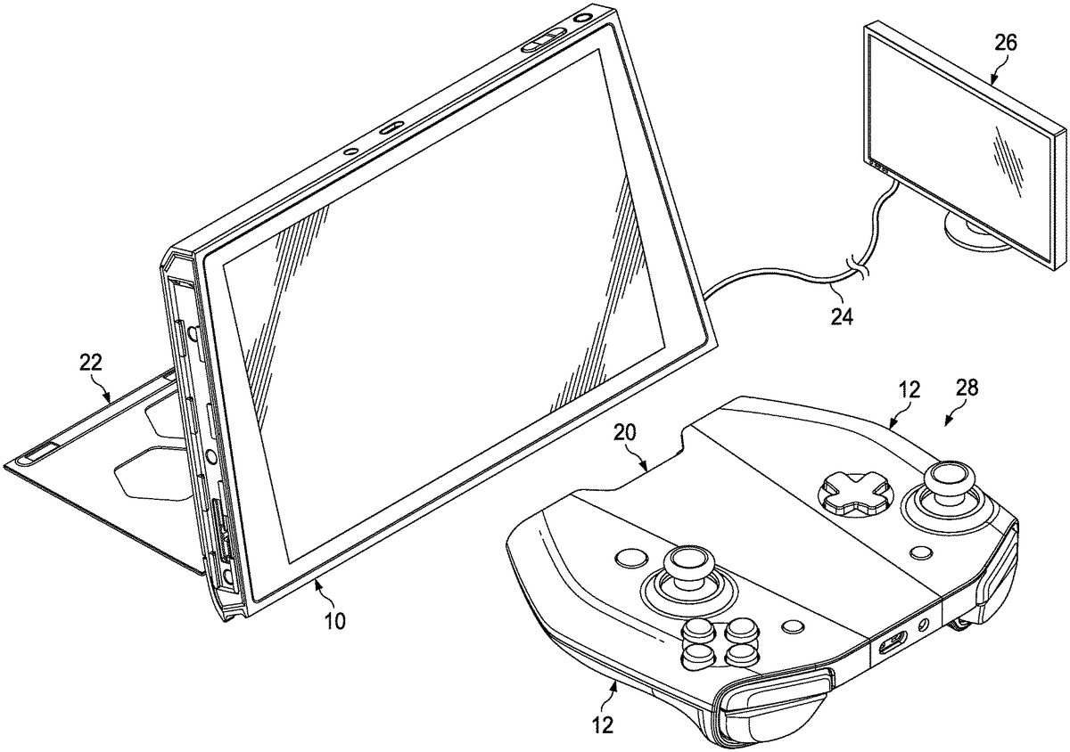
FIG. 1Cdepicts first and second game controllers12detachably coupled at opposing sides of a bridge20to build a composite game controller that interacts as a peripheral with portable information handling system10, such as by communicating game controller inputs to information handling system10through wireless signals. In the example embodiment, portable information handling system10has a stand22that extends out from the rear of its housing to hold portable information handling system10in an elevated viewing position. Stand22rotates about a hinge in the bottom portion of information handling system10to open from the top out, thus reducing space used by stand22. In this stand-alone mode of operation, portable information handling system10presents information as visual images based upon inputs from the composite controller assembly28through the wireless interface. Portable information handling system10is not restricted to executing gaming applications and may perform other processing tasks with interactions from other input devices, such as a keyboard and mouse. In addition, portable information handling system10may support presentation of information as visual images at peripheral displays26, such as through a display cable interface24. During gaming operations, a variety of interactions may be provided when a peripheral display26is available, such as using the integrated display to present configuration or other information while providing the game user interface at peripheral display26. Similarly, if a peripheral display26is interfaced while game controllers12couple directly to portable information handling system10, the end user may present the gaming application user interface at peripheral display26while operating game controllers12in the handheld mode depicted byFIG. 1Aand presenting configuration or other supporting information at the integrated display of portable information handling system10. In the example embodiment, portable information handling system10is built into a housing having a trapezoidal shape of parallel top and bottom sides with the top side of a shorter length than the bottom side. The trapezoidal shape aids system stability in a stand-alone resting mode and provides a physical indication to an end user of the housing orientation, such as to aid attachment of game controllers12in low light conditions in an ergometric manner readily understood by an end user.
FIG. 1Ddepicts an exploded view of portable information handling system10with example processing components that cooperate to process information. Generally, portable information handling system10has a tablet configuration that executes instructions to present information as visual images at an integrated display. For example, a planar housing30holds a motherboard32that interfaces plural processing components that cooperate to process information. In the example embodiment, motherboard32interfaces a central processing unit (CPU)34that executes instructions to process information with a random access memory (RAM)36that stores the instructions and information. A solid state drive (SSD)38or other persistent storage device stores instructions during power down states that are retrieved to RAM36at power up. For example, an operating system, such as WINDOWS, stored in SSD38is retrieved to RAM36to manage interactions with physical devices by applications stored in SSD38, such as gaming applications executable by CPU34. A chipset40interfaces with CPU34to manage physical operations of CPU34, such as clock speed, graphics interactions and memory accesses. A graphics processing unit (GPU)42interfaces with CPU34to accept visual information generated by the operating system and application for further processing that defines pixel values for presentation of a visual image at integrated display48and peripheral display26. A wireless network interface card (WNIC)44interfaces with CPU34to provide wireless communication, such as through WiFi, Bluetooth and other wireless interfaces. A USB hub46supports cable interfaces through a USB protocol, such as to communicate input device and graphics information with external devices. A display48, such as a liquid crystal display (LCD) or organic light emitting diode (OLED) display, is disposed over the processing components and interfaced with GPU42to present information as visual images. The example embodiment depicts only some of the various processing components that might be used in portable information handling system10, and various configurations of processing components may be selected in alternative embodiments to achieve desired performance goals.
In one example embodiment, planar housing30may have a relatively thick construction as compared with conventional tablet information handling systems to provide a robust system that withstands exertions common in gaming application input devices. For instance, the Z-axis or thickness relative to the plane of planar housing30may provide additional space to include active cooling devices, such as a cooling fan for rejecting thermal energy created by power dissipation at CPU34and GPU42. Active thermal rejection increases the capabilities of the CPU and GPUs that may be selected for processing information. In particular, a power GPU42provides enhanced visual processing that supports a positive end user experience in a gaming environment. In various embodiments, planar housing30may have varied dimensions that offer a balance between handheld and stationary usage cases and ergonomics versus portability.
Generally, portable information handling system10, game controllers12and bridge20cooperate to provide a flexible solution for a high quality gaming experience with optimal processing capabilities. The composite controller assembly28is implemented with a three-piece assembly having two game controllers12that unite to a bridge20to become a single functional composite game controller operative as a peripheral input device. Game controllers12detachably couple to either bridge20or information handling system10with an interchangeable attachment structure that readily converts the system between handheld and stationary operating modes. In the stationary use case, composite controller assembly28interfaces as a separate peripheral with information handling system10through wired and/or wireless connectivity while information handling system10acts as a stationary “head” device held in a viewing position by stand22. Composite controller assembly28provides a slim ergonomically-performant controller unit that can support inputs to other types of information handling systems. When assembled to information handling system10, game controllers12convert information handling system10into a robust handheld gaming unit with convenient grips and end user input devices disposed in proximity to the end user's grasp.
As an example of a usage scenario, an end user powers up information handling system10in the handheld configuration depicted byFIG. 1A. The end user end user, using a launcher such as Valve's Steam in Big Picture mode, initiates a game (gaming application). The gaming application presents the gaming user interface at integrated display48. The handheld mode allows the user to play the game while mobile, thus giving the user the flexibility of playing while walking around his home or while traveling. Once the end user reaches a location to play in a stand alone mode, the end user removes game controllers12from opposing sides of information handling system10, such as with a sliding detachment, places information handling system10on a support surface, such as elevated by stand22, and attaches game controllers12to bridge20to assemble a composite controller assembly28. The end user may then continue the game application with inputs made from game controllers12through bridge20to information handling system10.
Referring now toFIGS. 2A and 2B, a side perspective view of game controller12and bridge20illustrate an example embodiment of an attachment structure50to couple game controllers12to information handling system10and bridge20. Attachment structure50provides a robust mechanical interconnect between game controller12and information handling system10and bridge20that withstands forces commonly associated with gaming devices with ready detachment and attachment as desired by an end user. Solid coupling by attachment structure50prevents rattle and/or wobble between proximate housing that can disrupt wired communication signals passing through wired interfaces disposed within attachment structure50. Features of attachment structure aid proper alignment during coupling and discourage attempts to couple misaligned housings or reverse install a right/left handed game controller on an opposite side of an information handling system10or bridge20. When game controllers12attach to a bridge20or information handling system10, a clean appearance is provided without gaps, holes or raw exposed mechanical features. These advantages are provided with a number of different attachment structures as described in greater detail below.
The example embodiment ofFIGS. 2A and 2Bhas a magnetically guided short-throw “backbone” style rail coupling to mechanically couple game controller12to bridge20. At game controller12, attachment structure50has opposing lips54that define a rail with plural opposing slots52. Within a cavity defined by the opposing lips, a pogo pin connector56exposes plural pogo pins that provide a wired interface to processing components disposed within game controller12. At the opposing length of the cavity from pogo pin connector56, a latch58is disposed with an actuation button60exposed at the bottom outer surface of game controller12and ramp feature62formed in the cavity leading towards latch58. Attachment structure50of bridge20has opposing plural tabs64and a connector pad66disposed in a cavity defined between the opposing tabs64. In one example embodiment, an anti-wear strip, such as. Teflon, is located at the bottom of the slot to reduce wear from sliding and tighten the fit of attachment structure50. Tabs64are sized to fit within slots52and then slide under behind lips54. A latch connector68disposed in the cavity defined by opposing tabs64couples to latch58as attachment structure50slides to an engaged position having pogo pin connector56aligned with connector pad66. Ramp feature62aids in a tight connection of attachment structure50by pressing tabs64out and against the back side of lips54as sliding engage of attachment structure50completes with latch58coupling to latch connector68and aids with ejection of game controller12by facilitating a sliding ejection motion at latch release activation. In an alternative embodiment, attachment structure50may be reversed so that tabs64are disposed on game controller12and slots52are disposed on bridge20.
To help ensure proper alignment of attachment structure50, one or more magnets69are embedded in each of opposing sides of attachment structure50to attract for proper sliding alignment and/or repel if an improper alignment is attempted. Magnetic polarity of embedded magnets69is configured to selectively repel and/or attract attachment structure50when misalignment or proper alignment is attempted. For instance, an embedded magnet69located in a slot54is configured to have a polarity opposite that of a magnet located at a tab64that aligns with it so that game controller12biases into the correct alignment during attachment. A second magnet at a proximate slot54has an opposite polarity to the first magnet so that an attempt to couple game controller12with the tab64having the same polarity will repel the game controller12away from bridge20. A second magnet may also be included in bridge20with an opposite polarity of the second magnet of game controller12so that the attraction and repel interactions are reinforced along the length of attachment structure50. In one embodiment, polarity configurations are arranged at left and right side game controllers12and bridge20so that an attempt to couple a left side game controller to a right side of bridge20will provide a repelling force.
One advantage of attachment structure50in the example embodiment is that the short-throw arrangement of slots52and tabs64allow a sliding motion to attach game controller12to bridge20that involves only a portion of the length of attachment structure50. This smaller sliding motion helps to prevent exposure of attachment structure50visually after attachment is complete to avoid compromise of the appearance of composite controller assembly28. In the example embodiment, at the start of the sliding attachment motion, pogo pin connector56completely misaligns with connector pad66at initial alignment of the correct slot54and tab64so that pogo pin connector56runs across connector pads66during a sliding coupling motion resulting in the individual pogo pins of pogo pin connector56to contact the individual pads of connector pad66in a predictable pattern during attachment. As describe below, this pattern of contacts provides an indication to a processor in bridge20of the type of controller housing that is being attached. For instance, some controller housings may include additional peripheral functions that the contact pattern helps to discern before attachment is complete. For instance, game controller12may include speakers to enhance sounds or a battery to provide additional battery life to an information handling system. In the example embodiment, attachment structure50is depicted at a bridge20, however, information handling system10includes a substantially identical attachment structure has bridge20so that game controller12interchangeably couples to bridges and information handling systems with a small sliding attachment and detachment motion. In one alternative embodiment, the attachment structure50may be reversed so that the opposing lips52are integrated in bridge20and information handling system10with the tabs64integrated in game controller12.
Referring now toFIGS. 3A, 3B and 3C, a side perspective view depicts an alternative embodiment of an attachment structure50that couples a game controller12to a bridge20or information handling system10. In the example embodiment, attachment structure50has a dual guide feature72disposed at the side surface of game controller12that fit into dual guides70formed in bridge20and information handling system10. Dual guide feature70provides a gross to fine alignment with a narrow region of each feature72fitting into an enlarged region of each guide70that then slides so that the narrow region of each guide feature72engages under the narrow region of each guide70. In the example embodiment, only one of the guide features72bottom out on sliding engagement with the guide70so that predictable alignment is achieved. Upon a completed sliding motion, latch58extends to engage in latch opening68with a plug76wired interface contacting a socket74wired interface.FIG. 3Cillustrates an example embodiment of latch58that biases upwards and out of game controller12under the influence of a biasing device78, such as a spring. A press at latch button60overcomes the biasing force so that latch58levers against game controller12to withdraw from latch opening68. Attachment structure may be constructed from aluminum or a hard plastic to resist wear and lubricated with a Teflon material to reduce friction during the sliding motion.
Referring now toFIG. 4, a side perspective view depicts an alternative embodiment of an attachment structure that couples a game controller to a bridge or information handling system. The example embodiment provides a pair of opposing rails80with a double angled structure in which alignment is facilitated with an initially loose fit at an attaching member that slides down the rails towards a tighter fit when a latch locks game controller12in position. The long throw rail approach reduces a risk of misalignment, however, the longer sliding motion is less convenient for an end user.
Referring now toFIG. 5, a side perspective view depicts an alternative embodiment of an attachment structure that couples a game controller to a bridge or information handling system. Plugs extending from game controller12fit into openings of bridge20and slide to engage. A sliding connector84engages with a fixed connector of the bridge and slides relative to game controller12to remain interfaced with the bridge connector during the sliding motion. By sliding connector84during the coupling of game controller12, wear effects on the electrical connector is reduced over time since the pins remain engaged through the sliding motion of attachment.
Referring now toFIG. 6, a flow diagram depicts a process for tracking game controllers to accept inputs at an information handling system as game controllers attach and detach at an information handling system and bridge. In such a situation, the end user might experience delays related to pairing of the bridge before inputs from the game controller are provided to the gaming application and prioritization of different potential gaming inputs could become random or game specific behavior Although detachable game controllers12provide improved end user flexibility for selection of an input configuration to interact with a game executing on an information handling system, in a gaming environment plural game controllers and bridges may be available to input to an information handling system, which can result in confusion regarding which inputs should be used. For example, an end user might detach a game controller from an information handling system and couple the controller to any of plural nearby bridges to interact wirelessly with a gaming application. In such a situation, the end user would experience delays related to pairing of the bridge before inputs from the game controller are provided to the gaming application and prioritization of different potential gaming inputs would be random or game specific behavior. Further, where game controllers12have different configurations of hardware, such as integrated speakers and alternative input devices, attachment to a bridge would involve additional delays as hardware specific configuration information is exchanged between the bridge and information handling system. In a typical gaming environment, these configuration steps can potentially face additional confusion where multiple wireless devices are available during pairing discovery. In one example embodiment, a safety feature disables functionality for unknown game controller identifiers to help manage unexpected or third party controllers that are detected.
FIG. 6depicts logic that tracks game controllers that make inputs to an information handling system to manage different configurations that include a direct coupling of a game controller to the information handling system or indirect communication of the game controller with the information handling system through a bridge. One technique that aids in correct association of an end user with a game controller is to track end user association based upon a game controller unique identifier for each game controller associated with end user inputs. For instance, during a physical coupling with an information handling system, the unique identifier of the game controller is retrieved to the information handling system and stored with a wireless pairing profile. Similarly, during a wireless or USB coupling of a game controller with an information handling system through a bridge, the game controller unique identifier is retrieved to the information handling system and stored to aid tracking of the composite controller assembly that includes the game controller. Once pairing information is stored at the information handling system, wireless connectivity with a game controller is provided by including the game controller unique identifier in bridge pairing and advertising packets. During a re-configuration of a game controller between direct communication and indirect communication through a bridge, “activate” and “deactivate” states are included with conventional wireless connection state machines so that rapid and seamless game controller and bridge swapping are supported. In addition, composite controller assembly descriptors are defined that include each combination of identifiers associated with each game controller, such as where multiple game controllers are swapped in various combinations with multiple bridges to interface with an information handling system. In this manner, swapping between game controller input devices is managed through identification of the game controller unique identifier and component composition with transitions between configurations simplified through a deactivate state.
The process starts at step86with a start “not connected” state executing at a bridge processor. At step88, a game controller is attached to the bridge, such as with the attachment structure described above that interfaces the bridge and game controller wired interfaces. At step90, the bridge firmware determines if the bridge has paired with a “head” information handling system. If not, the process continues to step92to leave the configuration process flow and perform an initial pairing with an information handling system. In one example embodiment, advertising and pairing are automatically initiated in response to assembly of a game controller to the bridge. If the bridge is already paired, the process continues to step94to transition to an activating state and initiate an activating timer. The activating state proceeds to step96to determine if the bridge has both game controllers coupled as “wings” and, if so, ends with a connected state at step102. If the bridge does not have both controllers connected, the activating state continues to step98to increment down the timer and then to step100to determine if the timer has expired at a count of zero. If the timer has not expired, the process returns to step96to continue the activating state. If the timer expires at step100, the process returns to step86to restart when another game controller is coupled to the bridge.
Once the bridge firmware has transitioned to the connect state at step102, the process continues to step104to retrieve the unique identifier from each game controller wing coupled to the bridge. Once the game controller unique identifiers are retrieved, the firmware proceeds to step106to create a composite descriptor of the controller assembly based upon both game controller wing unique identifiers. At step108, the composite descriptor and the game controller unique identifiers are provided to the information handling system, which defines the composite controller as the “primary” device for the game controller type and sets other connected composite game controllers as secondary. In addition, at step104the process continues to step110to determine from the unique identifiers whether any of the game controllers were previously attached to the bridge as part of an existing composite device or as a directly connected device. If so, the process continues to step112to set the previously connected device to a “not connected” state. Once the unique identifiers are associated with the composite assembly at step108and step112, the game controller database is updated at step114and the process ends at step116.
Referring now toFIG. 7, a flow diagram depicts a process for managing deactivation of game controllers at detachment from a bridge. The process starts at step118in a connected state having first and second game controllers attached on opposing sides of a bridge. At step120, detachment of a game controller wing from the bridge is detected. The process continues to step124to transition the bridge firmware to a “deactivating” state and start a timer. At step126, a determination is made of whether all game controller wings are attached to the bridge and, if so, the process continues to step128to proceed to activation at step102ofFIG. 6. If both game controller wings are not connected at step126, the process continues to step130to decrement the timer and step132to determine if the timer has expired at zero. If the timer has expired, the process continues to step136to set the state to “not connected,” to update the database at step138, and to end at step140. If the timer has not expired, the process continues to step134to determine if any of the bridge's game controller wings are attached to another bridge. If not, the process returns to step126. If a game controller is determined as connected to another bridge, the process continues to step136to set the bridge to a not connected state, to update the database at step138and end at step140.
Referring now toFIG. 8, a logical block diagram depicts a storage structure for tracking game controllers12at an information handling system10and bridge20. Information handling system10includes operating system drivers144and/or device specific drivers150,152and154that interact with a composite device database156to present a composite device descriptor of composite controller assemblies28for use by an application executing on information handling system10, such as a gaming application. In the example embodiment, driver support is provided for communication with bridges20through USB, Bluetooth GATT and Internet Protocol. Various software and firmware structures and interactions may be used to coordinate communication between composite controller assemblies28and information handling system10. For instance, drivers may be implemented with multiple separate driver modules or one single monolithic driver. Composite device database156may be implemented as a file, a hive registry, an SQL database or other formats. Data representations may include binary, text or other formats. In a monolithic driver embodiment, a virtual device can be represented to allow transport and other elements of the devices to be changed without remunerating the virtual device.
In operation, each bridge20boots at power up, determines its connected components, such as by reading identification information of attached game controller12, and aggregates its identification with the connected component identifications to define a composite identity descriptor. Bridge20then interfaces with information handling system10through an available communication medium, such as USB, Bluetooth or IP, and registers with information handling system10. A monolithic driver144or an individual driver associated with USB150, Bluetooth152or IP154, interrogates the bridge20of the composite device28, such as through vendor specific control messaging, and obtains the composite identifier. The driver then reads composite device database156to see if the composite device28, bridge20or game controllers12are included as devices previously in use at information handling system10. If so, the driver in contact with the composite device interfaces with any companion drivers to remove the device from its connected devices. The connected driver then registers the composite device in composite database156and stores its identity descriptor. As components are added or removed, such as different bridges or changes to game controllers at different bridges, updated identifier information is provided through its active driver to maintain consistent tracking of bridges and game controllers interfaced with information handling system10. In one example embodiment, composite database156includes tracking of bridges and game controllers with a “pause” state that indicates a transition between connected and disconnected states, such as when a game controller is detached from information handling system10or bridge20to attach to a different device. In some cases, the MCU162on information handling system10and game controller(s)12directly connected to that MCU162represent the game controller(s)12as a composite device to the database via USB. In such an example embodiment, MCU(H)162of information handling system10could be managed the same way as the bridges20within the database, such as for example transitioning to different states depending on game controller12identifier tracking. Thus, for instance, game controller interactions with bridges and information handling systems are trackable as connected, disconnected, paused, active, inactive and other states so that transitions of composite devices, to include information handling system and controller composite devices, are actively managed to provide smooth operating transitions, such as during re-configuration of game controllers between different bridges and information handling systems.
Referring now toFIG. 9, a circuit block diagram depicts an example embodiment of an information handling system10attached at opposing sides of a housing160to first and second game controllers12for direct communication through a wired interface. In the example embodiment, information handling system10includes processing components within a housing160having an attachment structure as described above to attach to a game controller12housing. The example embodiment depicts a microcontroller unit (MCU)162that interfaces with connector pads66and accelerometers170through an I2C interface168. A USB interface166is provided to a system on chip164that provides USB hub and wireless communication support. Although the example embodiment depicts an MCU, other types of processors may be used and, in an example embodiment, the system CPU may directly couple to the connector pad66instead of communicating through MCU162. Each game controller12includes an MCU172that executes embedded code stored in flash memory to monitor for input device inputs and report the inputs through pogo pin connector56to information handling system10. In the example embodiment, input devices include input buttons associated with a joystick14and joystick and trigger inputs176. Other features that may be optionally supported include a speaker180that plays audio provided from information handling system10and a secondary battery supply182that supplements information handling system integrated battery storage. These additional features may be supported, for instance, with additional wired interface pins as described below. In addition to passing inputs to information handling system10, each game controller12includes a motor driver178that drives a haptic device to generate a haptic response, such as a vibration, with a drive command, such as pulse width modulation (PWM) or a logical vibration response level. In the example embodiment a vertical linear resonant actuator (LRA)184and a horizontal LRA186provide haptic feedback or “rumble” to the end user based upon commands communicated from information handling system10, such as a command for vibration at variable levels in horizontal and vertical orientations. In an alternative embodiment, a single eccentric rotating motor (ERM) or dual ERMs with horizontal and vertical orientation may be used. Accelerometers170integrated in information handling system10and game controller12detects vibration and gyroscopic orientation. As described in greater detail below, the amount of haptic feedback may vary based upon the physical configuration of the game controller, such as using a lower motor speed when in a low weight configuration coupled to bridge20and a greater motor speed when in a high weight configuration coupled to information handling system10. Haptic feedback may also vary based upon the orientation of game controller12, such as by adjusting the speed of the horizontal versus the vertical motor as orientation detected by gyroscopic function of the accelerometers170changes.
Referring now toFIG. 10, a circuit block diagram depicts an example embodiment of a bridge20attached at opposing sides of a housing to first and second game controllers12for supporting indirect communication of the game controllers12with an information handling system10. Bridge20includes a bridge MCU190that supports communication with an information handling system through a USB interface166and a wireless interface supported through a radio192. MCU190interfaces through an I2C interface168with an integrated accelerometer170and connector pad66. Bridge20communicates with game controllers12in a similar manner to information handling system10and acts as an intermediary with between game controllers12and information handling system10. For example, as inputs are made at game controller12, the input are communicated through the wired interface to bridge20and then forwarded from bridge20to information handling system10through a USB cable or wireless interface. Commands from information handling system10are similarly intermediated with communications to bridge20, which forwards the commands to game controller12, such as to provide haptic feedback. In the example embodiment, the identification and ground pins are located at the bottom of the connectors and the VDD power pin is located at the top so that inadvertent power on is protected against and to aid the timing of power up at a sliding attachment of a controller to an information handling system or bridge.
The distributed logic architecture ofFIGS. 9 and 10provides a flexible game console that adapts to both handheld and standalone use cases by interchangeably attaching game controllers to an information handling system housing and a bridge housing. In the example embodiment, scalability, modularity and responsiveness of game controllers12are enhanced by including a processor in each game controller that manages interactions with bridge20and information handling system10. Distributed MCU processing provides a number of advantages. One advantage is responsiveness of game controllers12and bridge20in communicating game inputs to information handling system. For example, each MCU executes a state machine that rapidly responds to events, such as inputs from a joystick, buttons and triggers and commands to haptic feedback devices. As another example, a scalable low pin count wired interface simplifies communications between game controllers12with bridge20and information handling system10. Defining a scalable low pin count interface allows ready attachment between a bridge or information handling system with adaptability for optional functions and hardware interfaces. For instance, event-based state machine management of inputs at a game controller and bridge share an I2C interface that can include support for other hardware through a common link. The low pin count leaves room at the wired interface to add pins for communicating hardware specific information through dedicated links, such as audio information or power transfer from a battery in a game controller to supplement power at an information handling system. The modular approach of separating a composite controller assembly into a bridge and two game controllers enhances reusability of each portion in different assemblies, reuse of common MCU embedded code and reduction of sometimes confusing wireless interfaces by leveraging bridge wireless communications. In one example embodiment, an application programming interface defined for the wired interface supports third party vendor devices to interface with a bridge or information handling system to enhance user options for game controllers and other accessories. To support adaptation to changing hardware and communication capabilities, firmware updates are coordinated across the wired and wireless interfaces with version control logic and malicious code protection as described in greater depth below.
Referring now toFIGS. 11A, 11B and 11C, a flow diagram depicts an example embodiment of identification by a bridge or information handling system of game controller type based upon wired interface contacts during a sliding attachment motion. Identification of pin count and configuration during a sliding attachment motion improves flexibility for integrating different types of functions within a game controller and supporting third party game controller implementations to create a rich ecosystem of compatible peripheral devices. For instance, various configurations of supporting hardware integrated in a game controller, such as peripheral speakers, a supplemental battery, a camera, a small display, etc. . . . , may include additional wire interface pin connections and/or a different order for the pins. Monitoring pin and pad interfaces of a wired connection through a sliding attachment motion supports detection of pin connection success across plural different game controller hardware and pin configurations, such as third party implementations that may vary the pin arrangement. In one example embodiment, detecting pin interfaces through sliding connection process allows elimination of some pins, such as identifier pins, since the game controller type is determined by the pin interfaces during the connection process. In one embodiment, the sliding connection pin interfaces may further supplement game controller operations by providing a power on command without a dedicated power on pin.
In the example embodiment depicted byFIG. 11, a magnet and Hall sensor are disposed in fixed positions at opposing sides of the attachment structure, such as with the Hall sensor interfaced with an MCU disposed in a bridge or information handling system. At step194, the first part of a game controller12attachment to a bridge20is started with alignment of a ground pogo pin8with an identifier pin1of the bridge. For instance, at initiation of attachment, the attachment structure misaligns both sides of the wired interface so that no pins connect with the sliding attachment motion first bringing the game controller12number1pin into contact with the bridge20number8pin. In one alternative embodiment, the number1pin is a dedicated identifier pin that provides identification of the game controller device. In an alternative embodiment, the number1pin may be repurposed after attachment to provide support for I2C communication, thus reducing the total pin count. At step194, a voltage out from the Hall sensor is provided to an analog pin of the bridge MCU so that the variable voltage out provides an indication of the presence of the magnet and its relative distance to the Hall sensor. At step196, the attachment structures slide from the misaligned position towards an alignment position with the relative voltage output by the Hall sensor reaching a high value half way through the sliding motion has the magnet and Hall sensor align with game controller12ground pin number8contacting the bridge number4pin. At step198as the sliding attachment motion completes, the voltage out from the Hall sensor decreases with the magnet moving farther away from the Hall sensor until the number8ground pins align at opposing sides of the wired interfaces. During the sliding attachment, each pin of the bridge20wired interfaces briefly touches ground to provide an additional indication of the alignment of both sides of the wired interface through the attachment process as described in greater detail below. In particular, the example embodiment illustrates that pins4through7of game controller12may be initially configured as empty and then used to supplement I2C and USB communication once the type of game controller and its features are identified.
Referring now toFIG. 12, a flow diagram depicts a process for detecting game controller active pin count during a sliding attachment motion. The process starts at step200with alignment of the attachment structures to an initial position with the wired interfaces misaligned. At step202, the bridge processor polls analog voltage output by the Hall sensor to estimate the relative location of the wired interfaces based upon an analog conversion of the detected voltage and sets the value L as the pin value. The wired interface relative alignment may be estimated based upon expected voltage levels, such as with a calibration performed after each completed attachment where the magnet ends at the same distance from the Hall sensor as it has on initial misalignment. Alternatively, relative alignment may be estimated as voltage levels change through the sliding attachment motion. At step204, a determination is made of whether the location determined by the Hall sensor has a value and, if not, the process returns to step202to continue polling for detection of a pin at the location indicated by the Hall sensor. Once the Hall sensor locates a pin with the output voltage at step204, the process continues to step206to determine whether the bridge pin number1is grounded. If the bridge pin number1is not grounded, the process continues to step208to determine if the location is the number1bridge pin. If the location is the number1bridge pin, a ground is expected so that a failure to detect ground continues to step210to end the process with an indication of a bad ground. If at step208, the location is not the number one pin, the process continues to step214to indicate that the pin location is empty. If at step206the bridge number1pin is grounded, the process continues to step212to store the pin location L as populated. From steps212and214, the process continues to step216to determine if the position L has reached the eighth and last pin. If not, the process returns to step202to continue with the detection of the next pin location. Once the final pin location is reached, the process ends at step218.
Referring now toFIG. 13, an alternative embodiment of game controller12pin arrangements is depicted having an identifier pin used as an indication of the number of used and empty wired interface pins. In the example embodiment, pins6,7and8of the bridge20connector66supports an identification pin at each location with communication between connector66and MCU162managed through first and second multiplexors220. In the example embodiment, if pin6is an identification pin, MUX1220routes pin6to ID_H1; if pin7is an identification pin, MUX2220routes pin7to ID_H2; and if pin8is an identification pin, it proceeds directly to ID_H3 at MCU162. Pins6and7alternatively configure through multiplexors220as a second I2C communication link, although other types of alternative interfaces may be used. Logic in MCU162selects multiplexor220routing based upon the location of the identification pin. For instance, at initial attachment MCU162polls each of pins6,7and8to determine which is the identification pin and selects the multiplexors accordingly.
Referring now toFIGS. 14A and 14B, a circuit block diagram depicts a seven pin count wired interface between an information handling system10and first and second game controllers12coupled at opposing sides. In the example embodiment, pin7is dedicated to a physical power switch control221that aligns to a guide button functionality so that during attachment of controller12to information handling system the guide presses power switch control221to power up game controller12. During attachment, interfacing the guide against power switch control221acts as a dedicated power button with a press to complete power up and down sequencing between game controller12and information handling system10. For example, 5V of power is provided through pin1to each game controller12. The identification pin6for both the left and right game controllers12is grounded to only provide an attachment indication when attachment is complete so that power is communicated from switch220.
Referring now toFIGS. 15A and 15B, a circuit block diagram depicts a six pin count wired interface between an information handling system10and first and second game controllers12having an identification pin repurposed to control power. In the example embodiment, a power control222, such as a diode, is disposed between MCU172and the identification pin assigned to pin6so that MCU172commands power up and down based upon the high or low value of identification pin6. When the identification pin is pulled low at connection to information handling system10, logic on MCU172and information handling system10coordinate to apply power to game controllers12at pin1with 3.3V and the game controllers enter power up. Using the identification pin as a dual purpose for both detecting attachment and commanding power up and down eliminates the need for dedicated pin7and the power switch of the embodiment ofFIGS. 14A and 14B. Although the example embodiments ofFIGS. 14A, 14B, 15A and 15Baddress attachment of game controller12to information handling system10, a substantially identical circuit may be used with attachment of game controller12and bridge20. Generally, information handling system and bridge attachments operate interchangeability to attach to game controllers12.
Referring now toFIG. 16, a circuit block diagram depicts an example embodiment having opposing pins pulled high and to ground to confirm attachment connections before game controller power up. In the example embodiment, game controller12has all pins at connector56pulled low and information handling system10has all pins at connector66pulled high. Electrical communication between connectors56and66is confirmed once all pins are shorted to ground. Once electrical connections are verified by short to ground, a power up sequence is initiated and applying power at game controller12breaks the ground connection there. To support connection testing, test circuit226provides a multiplexor220between connector66and MCU162at each pin to interface each connector pin66with both its logical pin at MCU162and a test pin at MCU162. At the game controller side, a high impedance circuit224interfaces with each pin of connector56to provide ground to each pin. The test VDD is applied by logic at MCU162so that the test pins can be read to determine ground. Once each test pin detects ground, a good connection of connectors56and66is determined and power up of the game controller breaks the ground connection at high impedance circuit224. In example embodiment, Schottky diodes are disposed in high impedance circuit224and p-channel FETs are disposed in test circuit228.
Referring now toFIG. 17, a flow diagram depicts a process for confirming game controller attachment with the example embodiment ofFIG. 16. The process starts at step228and at step230the game controller “wing” is connected to the information handling system or bridge. At step232, test circuit226sets the multiplexors220to route to the test pins of MCU162. At step234, the game controller high impedance test circuit224defaults to interface ground to the connector56. At step236, logic of MCU162turns on power to the test VDD to bring all of the pins of connector66to a high state. At step238, MCU162listens to each of the test pins to detect a high or low state. At step240, MCU162stores a list of the high or low states at each pin of connector66at step244. Once the test is completed, the VDD is powered on, which breaks the connection of the pin with the test VDD, the test VDD is powered down and MCU162queries the game controller to retrieve a list of the pins used by the game controller. At step246, a determination is made of whether the list is received and, if not, the process continues to step250to indicate an error. If the list is received, the process continues to step248to compare the list of active pins with the list of pins provided from the game controller. If a pin from the game controller list is not active, an error is indicated at step250. If all of the pins indicated as used by the game controller are active, the process ends at step252with an indication of a successful connection.
Referring now toFIG. 18a flow diagram depicts a process for updating firmware at game controllers12, bridges20and information handling systems10. Although interchangeability of game controllers with different capabilities as attached to different bridges and information handling systems provides improved flexibility for end users, changing configurations may result in different embedded code versions operating on the MCU within each game controller, bridge and information handling system. In order to ensure consistent communications and interactions, each MCU stores locally a firmware version and communicates the firmware version upon attachment. For example, embedded code firmware is stored in non-transient memory of the MCU or interfaced with the MCU, such as programmable static random access memory (SRAM) or other flash memory devices. If one device in an attached configuration has a more recent firmware version than another device, the firmware update process depicted byFIG. 18is initiated to update the embedded code. In one example embodiment, each MCU in the game controller, bridge and information handling system executes a common version of embedded code that supports individual device functions based upon identification of the device type. With the same embedded code distributed to game controller, bridge and information handling system MCUs, the MCU with the most updated embedded code copies its firmware to the other devices. In one example embodiment, a game controller with a most updated embedded code version copies the embedded code to an information handling system, which in turn copies the update to a second game controller attached at an opposing side of the information handling system. A similar process may take place where a bridge receives a firmware update from a first game controller and provides the update to a game controller at an opposing side of the bridge.
A most likely firmware update scenario involves the information handling system getting firmware updates through a network interface and communicating the firmware updates directly to attached game controllers, directly to a bridge through a wireless or USB interface, or indirectly to game controllers that are attached to a bridge. If the information handling system, bridge and game controller MCUs run different code, a copy of each device type firmware may be stored on each device to support updates between devices. In some instances, older versions of firmware may be stored at a device to execute in a situation where an attached device cannot perform an update. Security measures to ensure that malicious code is not loaded may include a verification or security code associated with an update, such as based upon a hash of the update.
In the example embodiment, an embedded code update is initiated from a host information handling system device to a “wing” game controller device. In alternative embodiments, as described above, firmware updates may be initiated from any device that has a most recent embedded code version. The process starts at step254with a request by the host operating system, such as WINDOWS, to initiate a game controller MCU embedded code update. The “head” information handling system communicates the requested update at step256as a reset command to place the game controller MCU in a bootloader mode. At step258, after entering the bootloader mode the game controller responds with a message indicating that it is prepared to accept the update. The information handling system MCU at step260forwards the bootloader initiated message to the host operating system. At step262the host operating system sends 32 Byte firmware update packets to the information handling system MCU, which, at step264, forwards the firmware update packets to the game controller MCU. Steps262and264repeat until the firmware update transfer to the game controller is complete. At step266, the host operating system sends an update done message to the information handling system, which, at step268forwards the update done message to the game controller MCU. At step270, the game controller MCU computes a checksum of the firmware update and sends the checksum to the information handling system MCU, and at step272the information handling system MCU sends the checksum to the host. The game controller MCU executes the firmware update and enters normal operational mode to communicate with the information handling system MCU through an I2C link, which provides communication to the host through a USB link.
Referring now toFIG. 19, a flow diagram depicts a method for adapting haptic response at a game controller based upon the type of operational configuration of the game controller. As described above, each game controller12integrates one or more haptic devices that provides a haptic feedback to an end user, such as eccentric rotating mass motor (ERM) that generates vibration by rotating a weight off center from a rotational axis or a linear resonant actuator (LRA) that generates vibration using magnetic fields and electrical fields. In one example embodiment, a first haptic device generates vibration in a first plane and a second haptic device generates vibration in a second plane, such as perpendicular to the first plane. As described above, each game controller may attach to both an information handling system housing or a bridge housing. Since the information handling system has a greater mass than the bridge, a given haptic response will vary depending upon the weight of the device as a whole so that a haptic response at an information handling system will have less vibration than the same response at a bridge. In an embodiment where different hardware configurations exist for game controllers, bridges and information handling systems, the mass of each attached device will have an impact on haptic device feedback felt by an end user. To adjust for different system total mass with different configurations, haptic feedback is adjusted based upon total mass and refined based upon accelerations sensed at the information handling system. For example, an accelerometer detects actual haptic response for the game controller MCU to compare against intended haptic response so that the haptic device operation can be adjusted, such as by changing the pulse width modulation applied to an ERM that generates vibration. One advantage to compensating haptic response based upon detected accelerations is that other factors are also taken into account, such as the tightness of an end user grip on the game controller, the mass of an end user's hands and situations where haptic response is unhelpful, such as when the game controller is resting on a table resulting in excessive vibration. In addition, orientation of the game controller sensed by the accelerometers can adjust haptic response from different haptic devices integrated out of plane from each other, including a direction of the rotation of an ERM between clockwise and counterclockwise.
The process starts at step276and continues to step278to determine if the game controllers are attached to an information handling system, such as by retrieving device type information from the information handling system MCU. If the game controllers are attached to an information handling system, the process continues to step280to place the game controller haptic device in a high weight configuration. For instance, a full haptic response is generated and communicated to the haptic device to ensure that adequate vibration is felt by the end user. At step282, the information handling system MCU passes rumble control commands to generate the haptic response with the full ERM motor speed to the game controller MCU. The process then continues to step284to determine if accelerometers at the game controller and/or the information handling system detect vibration expected for the commanded haptic response. If yes, the process returns to step278to continue monitoring haptic response. If the haptic response differs from the expected response at step284, the process continues to step292to modify the commanded haptic response to compensate for the response detected by the accelerations. For instance, if the haptic response detected by accelerometers exceeded the expected haptic response, a lower ERM rotation speed is commanded; and if the haptic response detected by accelerometers does not meet the expected haptic response, a higher ERM rotation speed is commanded. Similar adjustments are applied in an LRA haptic device is used instead of an ERM haptic device.
If at step278the game controllers are not attached to an information handling system, the process continues to step286to determine if the game controllers attach to a bridge, such as by exchanging a device type identifier with the bridge MCU. If the game controllers are connected to a bridge device, the process continues to step288to configure the haptic response at a low weight configuration, such as having a reduced haptic response in proportion to the weight of the game controllers attached to the bridge instead of the information handling system. At step290, the haptic response commanded to the haptic device is reduced based upon the reduced weight. The process then continues to step284to compensate for any differences between detected accelerations and expected accelerations of the haptic response. If at step286neither the bridge nor information handling system is attached, the process determines no controller and returns to step278. At step290, the modification of the haptic response for the reduced weight configuration, such as the lower ERM rotation speed, may be determined at the information handling system and sent to the bridge or the bridge may alter the full haptic response received from the information handling and provided to the game controller. In one embodiment, logic in the game controller MCU reduces the full haptic response commanded by the information handling system or bridge to compensate at the game controller for the reduced weight. As described above, the adjustments determined by monitoring sensed accelerations can include adjustments to vertical versus horizontal LRA axial vibration or ERM rotation and adjustments to the rotational direction of different ERM.
Referring now toFIG. 20, a flow diagram depicts a process of adjusting haptic response based upon an orientation of a game controller. In various embodiments, the haptic response may be generated with an ERM, LRA or other types of vibration-generating devices. For instance, LRA haptic devices tend to provide better control of the vibration axis compared with ERM haptic devices so that a game controller with horizontal and vertical vibration control may be implemented with two LRA devices oriented perpendicular to each other. The process starts at step296and, at step298a determination is made of whether the game controller has a sideways orientation. Generally, while playing a game the game controller is expected to be within the 90 degrees of rotation distance from the user plane. That is, the end user's expected orientation provides a plane of expected orientation of the game controller that identifies how much relative rotation should apply to first and second vibration response, such as LRA axial vibration or eccentric rotating masses rotating about perpendicular axes. If the game controller is sideways, the process continues to step300to retrieve from gyroscopic logic of the accelerometer the degree of rotation about the axis of gravity. If the game controller is not sideways at step298, the process continues to step302to detect the rotational degree of the game controller relative to the ground plane. These determinations of relative orientation provide an X value to input to the modulus equations of step304that define a vibration response of a vertically-orientated and horizontally oriented haptic device. The process then returns to step296to continue monitoring game controller orientation and adjusting vertical and horizontal vibration response. In one example embodiment, haptic response is programmable by an end user interface so that the end user can adapt haptic response as desired for a specific controller or gaming application, such as changes to the intensity of haptic response and changes to directional impulses.
Referring now toFIG. 21, an exploded view of a game controller12depicts a vertical axis trigger assembly to accept end user trigger inputs. Since game controller12couples both directly to an information handling system housing and to a bridge that supports peripheral operation, game controller12input devices adapt to both types of configurations with a vertically aligned trigger motion. In particular, when game controllers12attach at opposing ends of an information handling system housing, the end user grasp supports not just actuation of input devices but also hand held viewing of a display integrated in the information handling system tablet form factor. A vertically aligned trigger motion aids end user grasp at the periphery of the information handling system housing while disposing actuation structure in plane with the tablet planar housing form factor, thus minimizing the impact of the input devices on system portability when game controllers12are attached. A difficulty with this arrangement is that index and middle fingers that typically interact with a trigger can exert a substantial force on a trigger input device. To withstand this force and provide a robust input device with repeatable and nonbinding inputs, a trigger subassembly with vertically aligned input rotation provides ideal trigger tactile feedback and response time for trigger inputs in a comfortable end user grasp.
In the example embodiment, a trigger310couples as a subassembly to a midframe assembly308to provide robust trigger inputs independent of a cosmetic outer housing. Coupling the trigger310as a subassembly provides isolation and independent actuation for trigger movement and reduces complications associated with manufacture and assembly of the game controller. Trigger310pivots about a vertical rotational axis relative to the plane of a grasped information handling system housing that aligns with an input fingers natural motion. In the example embodiment, a midframe308provides the main structural integrity of the game controller with attachment structure50defined at a side surface to attach to an information handling system housing. For instance, attachment structure50at the side surface of midframe308defines slots with an enhanced material thickness for a robust information handling system attachment in combination with lips that overlap the side surface when a cosmetic housing couples over midframe308. An opening in the side surface of attachment structure50provides space for a wired connector, such as pogo pins56, disposed at a printed circuit board306to insert through and interface with an information handling system wired interface. Printed circuit board306couples to an upper surface of midframe308with screws314to provide communication between the input devices, MCU and pogo pin connector56. A trigger input button316located at one end of printed circuit board306to detect inputs at trigger310. In the example embodiment, a secondary button312is provided above trigger310to accept press inputs detected by an upper portion of trigger input button316. Input button314provides a press input device separate from trigger310, although in alternative embodiments input button314may have a vertically aligned rotation similar to trigger310to provide a double trigger input device.
In the example embodiment, trigger310couples to midframe308to rotate about a vertical axis defined by a dowel pin axle334extending up from midframe308and coupling to a bracket in trigger310subassembly, as described in greater detail below. In addition, trigger310motion is defined by a member318that fits in a guide320integrated in midframe308. Rotation about axle334provides a rotation axis at an outer perimeter of midframe308relative to the position of attachment structure50so that a finger extending from an end user grasp at the outer perimeter activates trigger310about a natural rotation axis. For instance, an end user grasp around the perimeter of an information handling system having a game controller attached places trigger310in position for a finger to activate at a front outer edge of the complete assembly.
Referring now toFIG. 22, an exploded view depicts game controller covers322and326aligned to assemble to midframe308. In the example embodiment, midframe308has a completed assembly with joystick14coupled to printed circuit board306, buttons16coupled to printed circuit board306, button312coupled to midframe308and trigger310coupled to midframe308. Upper housing322encloses the upper surface of midframe308and lower housing326encloses the lower surface of midframe308with an end cap324securing upper housing322to lower housing326with screws314. A bezel328couples to upper housing322and lower housing326to encircle trigger310and button312. As is illustrated by the uncovered midframe, trigger310couples to midframe308independent of upper housing322and lower housing326so that operation of trigger310does not rely upon support of the decorative outer coating of game controller12. The separated construction provides a more robust trigger310in the face of large end user input forces.
Referring now toFIG. 23, an exploded view depicts a trigger subassembly that couples to a game controller midframe. A trigger bracket330couples directly to midframe308, such as with screws. Dowel pin axle334inserts through vertically aligned openings of trigger bracket330and through openings338formed at the rotational axis location of trigger310. A torsion spring332fits over dowell pin axle334to create a biasing force that biases trigger310away from midframe308. During manufacture, trigger bracket330is assembled to have trigger310coupled by dowel pin axle334with spring332engaged so that the subassembly is then coupled to midframe308, thus reducing assembly time and complexity. Guide member336fits into a guide formed at midframe308to further simplify assembly and guide trigger310motion during trigger inputs.
Referring now toFIG. 24, a lower perspective view depicts trigger310actuation at a midframe308.FIG. 25depicts trigger310actuation from a bottom view. Trigger310rotates about a vertical axis towards midframe308without relying upon any outer cosmetic cover as support. An elastomeric end stop dampener integrates with midframe308at a stop point for trigger310rotation to absorb the force of an end user trigger input. A gap342formed in midframe308at the periphery of trigger motion aids in guiding trigger310towards dampener340. Button312actuates separate from trigger310and also supported by midframe308without relying upon the outer housing.
Referring now toFIG. 26, a lower front perspective view of midframe308illustrates guide structures disposed to aid in trigger motion. In the example embodiment, elastomeric dampener340integrates with midframe308structure to provide a firm stop for trigger motion with force partially absorbed at the stop by elastomeric material, such as an elastomeric plastic. A trigger guide tab336extends out from a midframe guide rail320to engage with the trigger and guide trigger motion. A button guide tab344extends out from midframe guide rail320to guide button motion at a press towards midframe308.
Referring now toFIGS. 27A and 27B, a lower perspective exploded view depicts an illumination assembly that provides illumination at a joystick14extending from an upper surface of game controller12. Illumination of different colors and intensities at game controller12provide indications to an end user about both the operational status of the game controller and gaming application status communicated from a gaming application executing on an information handling system, either through a direct wired interface or through indirect bridge communications. In the example embodiment, lighting effects are provided in a controlled and focused manner by directing illumination of a desired color and intensity at a circumference defined around the base of joystick14. In some local operational instances, an MCU of game controller12locally determines the illumination for presentation. For instance, during a power up boot, a local game controller MCU might flash a first color and, after communication is configured for a coupled bridge or information handling system, the local MCU might flash another color as a success indication before handing control of illumination to the bridge or information handling system. Other types of locally determined illumination by the game controller MCU may include a failure to communicate with a bridge or information handling system, a mismatched firmware or hardware version. In some instances, illumination control is determined at bridge to present operational status as determined by the bridge, such as a lack by the bridge of a communication interface with an information handling system through USB, Bluetooth or IP communications. In addition, these operational status indications may be commanded from an information handling system to the illumination assembly where operational status issues are determined at the information handling system. In an operational mode, illumination color and intensity is supported by the operating system so that gaming applications can include indications that might include gaming events, such as loss of life, life status, alerts, etc. . . . .
To direct illumination to a defined region at joystick14, a plurality of red, green and blue (RGB) LEDs356are powered through a flexible printed circuit board strip that is mounted in a circular fashion around a translucent plastic light guide, such as may be formed with a double shot injection molding process. The top housing light guide322has a translucent region proximate joystick14and formed as an inner circumference at the opening through which joystick14extends. A non-translucent region354is defined around the outer circumference of the translucent region to form a boundary at which illumination is contained. A light guide360integrated in housing322, such as with a double shot plastic injection of a translucent plastic, forms an enclosure that surrounds joystick14and defines a pathway through which illumination proceeds from the interior of game controller12to translucent region352. An LED gasket350couples around the base of light guide360to have openings through which LEDs356of light ring flexible printed circuit348fit to transmit light into light guide360. LED light gasket350seal illumination to proceed into light guide360without leaks into the game controller main body that might distract an end user. In one embodiment, non-translucent region354and region358is treated to prevent transmission of light, such as with a layer of paint or other covering. In another embodiment, light guide360is formed as a separate piece that assembles into game controller12with light gasket350and light right flexible printed circuit board coupled into place. Light ring flexible printed circuit board has a tail that couples to the game controller main printed circuit board to accept commands from the game controller MCU that defines illumination color and intensity.
Referring now toFIG. 28, an upper perspective view depicts a controller housing conical light guide portion. The light guide360accepts illumination from a side surface about its circumference to allow space for a generous array of LEDs for good variations in LED color and intensity. Inner portions of light guide360may be treated to direct light towards the circular opening through which the joystick fits and to prevent illumination leakage where such leakage could distract an end user. A mount clearance area358fits over portions of the joystick and aids in alignment at assembly.FIG. 29depicts a side perspective view of flexible printed circuit348having LEDs356to illuminate a joystick. A mount clearance358aligns with that of light guide360to aid in assembly and coupling of the flexible printed circuit board to the main game controller printed circuit board.
Referring now toFIG. 30, a side cutaway view depicts a joystick14illuminated by five LEDs356mounted at a bottom location. LEDs356tend to have difficulty directing illumination from the bottom location towards joystick14due to the interference area of the encasement around joystick14and the optical lens provided to a light guide that directs the illumination toward the game controller upper surface.FIG. 30Billustrates non-uniformity that is provided by the bottom illumination at a translucent region352.FIG. 30Cillustrates reduced illumination levels achieved at the joystick14circumference translucent region352.
Referring now toFIG. 31, a side cutaway view depicts a joystick14illuminated by ten LEDs356mounted at a side location. The greater surface area of light guide360around its circumference provides space to arrange LEDs356to direct illumination in an efficient and effective manner towards translucent region352. As a result, illumination uniformity depicted byFIG. 31Bis improved relative to bottom illumination and a greater illumination intensity is available as depicted byFIG. 31C.
Although the present invention has been described in detail, it should be understood that various changes, substitutions and alterations can be made hereto without departing from the spirit and scope of the invention as defined by the appended claims.
Claims
- An information handling system comprising: a main housing integrating a processor, a memory, at least one communication medium and a display, the processor operable to execute a gaming application stored in the memory to generate visual images at the display, the main housing having first and second attachment structures disposed at opposing sides;a bridge housing integrating a processor and the at least one communication medium to communicate with the information handling system communication medium, the bridge housing having the first and second attachment structures disposed at opposing sides;first and second controller housings integrating a processor and plural input devices operable to accept inputs from an end user, each of the first and second controller housings having the attachment structure disposed at one side;and a wired interface disposed in each of the attachment structures;wherein the first and second controller housings detachably couple to the main housing and the bridge housing by engagement of the attachment structures to align the wired interfaces, the controller housing input devices communicating directly with the information handling system processor through the wired interface when the first and second controller housings couple to the information handling system housing, the controller housing input devices communicating indirectly with the information handling system through the wired interface and the at least one communication medium when the first and second controller housings couple with the bridge housing.
- The information handling system of claim 1 wherein the at least one communication medium comprises a wireless personal area network.
- The information handling system of claim 1 wherein the at least one communication medium comprises a universal serial bus cable.
- The information handling system of claim 1 wherein: the main housing has a trapezoidal shape having opposing parallel sides and opposing non-parallel sides;and the first and second attachment structures are disposed in the non-parallel sides.
- The information handling system of claim 1 further comprising: a magnet disposed in each attachment structure of the information handling system housing and bridge housing to have a first polarity;and a magnet disposed in each attachment structure of the first and second controller housings to have a second polarity;wherein the first and second polarity repel when the attachment structures align to an opposite of an intended side.
- The information handling system of claim 1 wherein the input devices comprise: a joystick extending upwards from each of the first and second controller housings;and at least one trigger extending from a side surface of each of the first and second controller housings.
- The information handling system of claim 1 further comprising a kickstand disposed on a rear surface of the main housing opposite the display, the kickstand selectively extending to hold the main housing in a raised position rested on a support surface.
- The information handling system of claim 7 wherein the wired interface comprises: pogo pins disposed in the first and second controller housing attachment structure;and contact pads disposed in the main housing and bridge housing attachment structures.
- The game controller of claim 8 wherein the attachment structure comprises: opposing lips at upper and lower sides of the controller housing side surface, each lip having plural slots;and tabs extending from upper and lower sides of the main housing, the tabs sized to fit into the slots and sliding behind the lips.
- A method for interacting with an information handling system, the method comprising: communicating inputs made at input devices integrated in first and second controller housings detachably coupled to opposing sides of the information handling system, the inputs communicated through a wired interface disposed between each of the first and second controller housings and the information handling system;detaching the first and second controller housings from the information handling system;detachably coupling the first and second controller housings to opposing sides of a bridge;communicating the inputs through the wired interface disposed between each of the first and second controller housings and the bridge;and communicating the inputs from the bridge to the information handling system through a communication medium.
- The method of claim 10 wherein the wired interface comprises: plural pogo pins disposed at one side surface of each of the first and second controllers;and plural contact pads disposed at each of opposing side surfaces of both the information handling system and bridge, the plural pogo pins aligning with the plural contact pads when the first and second controllers couple to the information handling system and to the bridge.
- The method of claim 11 wherein the communication medium comprises a cable coupled between the bridge and the information handling system.
- The method of claim 11 wherein the communication medium comprises wireless signals communicated between the bridge and the information handling system.
- The method of claim 10 further comprising: extending a stand from a rear side of the information handling system;resting the stand on a support surface to hold a display of the information handling system in a viewing position;and sending inputs from the first and second controllers through the bridge to the information handling system.
- The method of claim 14 further comprising: coupling the information handling system to a peripheral display;and presenting inputs as visual images at the peripheral display.
- The method of claim 14 wherein the input devices include at least a joystick disposed at the upper surface of each controller housing.
- A game input system comprising: a game controller housing;a game controller attachment structure integrated in one side of the game controller housing and configured to detachably couple to an information handling system housing and a bridge housing;a joystick extending from and upper surface of the game controller housing;a processor disposed in the game controller housing and interfaced with the joystick;and communication pogo pins integrated in the game controller housing at the game controller attachment structure and interfaced with the processor;wherein the communication pogo pins communicate joystick inputs to an information handling system when the game controller attachment structure couples to an information handling system and to a bridge when the game controller attachment structure couples to a bridge, the bridge communicating the joystick inputs to the information handling system.
- The game input system of claim 17 further comprising: a bridge housing;an bridge attachment structure integrated in each of opposing sides of the bridge housing, the bridge attachment structure configured to detachably couple to the game controller attachment structure;a bridge processor disposed in the bridge housing;communication pads disposed in the bridge attachment structure and interfaced with the bridge processor, the communication pads aligned to contact the communication pogo pins when the bridge housing couples to the controller housing;and a communication medium interfaced with the bridge processor;wherein the bridge processor receives joystick inputs through the communication pads and forwards the joystick inputs to the information handling system through the communication medium.
- The game input system of claim 18 further comprising: a first magnet disposed in the game controller housing having a first polarity;and a second magnet disposed in the bridge housing having a second polarity opposite the first polarity;wherein the first and second magnets repel when the game controller housing and the bridge housing align to couple at an opposite of an intended side.
- The system of claim 19 wherein: the game controller attachment structure comprises opposing lips formed in the game controller housing, each of the opposing lips having plural slots;and the bridge controller attachment structure comprises plural tabs sized to fit through the slots and slide behind the lips.
Disclaimer: Data collected from the USPTO and may be malformed, incomplete, and/or otherwise inaccurate.