U.S. Pat. No. 11,260,289
CLICKER MECHANISM FOR A VIDEO GAME CONTROLLER
Issue DateApril 20, 2020
Illustrative Figure
Abstract
A clicker mechanism for a game controller is disclosed. The clicker mechanism comprises a taper-shaped member and a barrel. A screw member is threadably affixed at a top portion of the taper-shaped member for adjusting the pull distance. The barrel is removably extends from a bottom portion of the taper-shaped member. A cam is disposed at an inner portion of the taper-shaped member with snaps at one end and a cam stopper pin at another end. A clicker connects to a bottom portion of the taper-shaped member, wherein the clicker is pressed downwards to create a rotational force on the cam which locks the snaps to the screw member to hold the adjustable levers in position, and wherein the clicker is released to create a rotational force on the cam which unlocks the snaps from the screw member and allows movement of the adjustable levers.
Description
DETAILED DESCRIPTION OF THE INVENTION A description of embodiments of the present invention will now be given with reference to the Figures. It is expected that the present invention may be embodied in other specific forms without departing from its spirit or essential characteristics. The described embodiments are to be considered in all respects only as illustrative and not restrictive. Referring toFIG. 1, a clicker mechanism100customizably fastened to a housing unit is disclosed. In one embodiment, the clicker mechanism100is securely affixed to adjustable levers (5aand7a) of the housing unit101on both sides of a game controller or joystick120via attaching members112(shown inFIG. 3). In one embodiment, the housing unit101is securely mounted on a game controller or joystick120along with the respective position of one or more detachable and customizable levers (5aand7a) in reference to the buttons and triggers of the game controller120. In one embodiment, the clicker mechanism100is configured to make the buttons and triggers of the game controller120more accessible for a user with the use of detachable levers (5aand7a). In one embodiment, the clicker mechanism100is further configured to prevent accidental activation of the levers or arms (5aand7a) by the user while playing. Referring toFIG. 2, the customizable levers (5aand7a) are configured to secured to the housing unit101of the clicker mechanism100is disclosed. In one embodiment, the housing unit101is configured to securely affix to the game controller120. In one embodiment, the housing unit101is made of a material, but not limited to, plastic. In one embodiment, the housing unit101is further configured to securely receive the clicker mechanism100on both sides to enable the user for simply and quickly accessing the buttons and triggers of the game controller120with the use of detachable levers (5aand7a). In one embodiment, the clicker mechanism100is made of a material, but not limited to, plastic. Referring toFIG. 3, the clicker mechanism100further configured to ...
DETAILED DESCRIPTION OF THE INVENTION
A description of embodiments of the present invention will now be given with reference to the Figures. It is expected that the present invention may be embodied in other specific forms without departing from its spirit or essential characteristics. The described embodiments are to be considered in all respects only as illustrative and not restrictive.
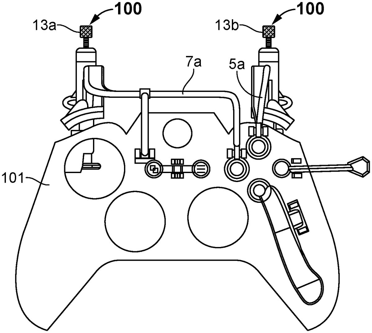
Referring toFIG. 1, a clicker mechanism100customizably fastened to a housing unit is disclosed. In one embodiment, the clicker mechanism100is securely affixed to adjustable levers (5aand7a) of the housing unit101on both sides of a game controller or joystick120via attaching members112(shown inFIG. 3). In one embodiment, the housing unit101is securely mounted on a game controller or joystick120along with the respective position of one or more detachable and customizable levers (5aand7a) in reference to the buttons and triggers of the game controller120. In one embodiment, the clicker mechanism100is configured to make the buttons and triggers of the game controller120more accessible for a user with the use of detachable levers (5aand7a). In one embodiment, the clicker mechanism100is further configured to prevent accidental activation of the levers or arms (5aand7a) by the user while playing.
Referring toFIG. 2, the customizable levers (5aand7a) are configured to secured to the housing unit101of the clicker mechanism100is disclosed. In one embodiment, the housing unit101is configured to securely affix to the game controller120. In one embodiment, the housing unit101is made of a material, but not limited to, plastic. In one embodiment, the housing unit101is further configured to securely receive the clicker mechanism100on both sides to enable the user for simply and quickly accessing the buttons and triggers of the game controller120with the use of detachable levers (5aand7a). In one embodiment, the clicker mechanism100is made of a material, but not limited to, plastic.
Referring toFIG. 3, the clicker mechanism100further configured to prevent excessive motion of the user's fingers while using the game controller120. In one embodiment, the clicker mechanism100is securely affixed to housing unit101via the attaching member112. In one embodiment, the clicker mechanism100comprises a taper-shaped member or tapered member102. The taper-shaped member102is securely affixed to the lever5aof the housing unit101of the game controller120. In one embodiment, a screw member13bis movably and threadably affixed at a top portion of the taper-shaped member102. The screw member13bis configured to move outward and inward from the taper-shaped member102. In one embodiment, the clicker mechanism100further comprises a barrel with fixed internal ribs104with a stopper pin110. In one embodiment, the taper-shaped member102includes arm guides. The arm guides prevent the barrel104from deflecting left to right or in the x-axis so the levers or triggers (5aand7a) do not slip off the buttons of the game controller120. The barrel104is removably positioned into the taper-shaped member102from a bottom portion. The stopper pin110is affixed to a top portion of the barrel104and configured to move along an opening118(shown inFIG. 8) of the taper-shaped member102. In one embodiment, the clicker mechanism100further comprises a cam and a cam stopper pin105, which is moulded and positioned in an inner portion of the barrel104. In one embodiment, the clicker108includes snaps at one end and a cam stopper pin105at another end. The cam stopper pin105is configured to stop the cam105from moving out of the barrel104. In one embodiment, the clicker mechanism100further comprises a clicker108, slidably positioned into the barrel104. The clicker108is configured to enable the cam stopper pin105to move inward and outward from the barrel104.
Referring toFIG. 4, the clicker mechanism100is activated via the clicker108is disclosed. In one embodiment, the user could activate the clicker mechanism100to make the buttons and triggers of the game controller120(shown inFIG. 2) more accessible for the user with the use of customizable levers (5aand7a). In one embodiment, the user could adjust the pull distance by rotating the screw members13boutwards and inwards from the taper-shaped member102. When the user clicks or presses the clicker108with fingers, it creates a rotational force on the cam105which locks the snap to the screw member13bto hold the adjustable levers (5aand7a) in position, wherein the clicker108is released to create a rotational force on the cam105which unlocks the snap from the screw member13band allows movement of the adjustable levers (5aand7a). The cam stopper pin105prevents the cam104from moving out of the barrel104. The user could easily access the buttons on the game controller120using the clicker mechanism100and allows maximum control over the operation of the video game. The clicker mechanism100allows the user to respond quickly within less time and shortens the reaction in the game for leading to increase control in a myriad of gaming situations and also makes it possible for differently-abled gamers to customize their controller to their best advantage.
Referring toFIG. 5, the arrangement and operation of the clicker mechanism100on turning on the clicker108is disclosed. In one embodiment, the clicker mechanism100further comprises a spring116, which is connected to the cam105. When the clicker108is pressed, the spring116inside the taper-shaped member102is compressed and the cam stopper pin105is connected to the screw13b. This mechanism locks the lever5ain position and prevents any movement of lever5aon exertion of external force. This in turn fully extends the screw13bin communication with the cam stopper pin105, providing zero pull. To adjust or add the pull distance, the screw members13bis rotated outwards or inwards by the user.
ReferringFIG. 6, the cam stopper pin105could be released on pressing the clicker108again. This action compresses the spring116even more, which rotates the cam stopper pin105to a second position. Then, the cam stopper pin105slides to the right and allows full stroke from 0 starting point without coming in contact with the screw13b.
ReferringFIG. 7, the adjustable screw13bis adjusted to a specific distance for limiting the pull distance. In one embodiment, the screw adjustment point is adjustable using trigger pull adjustment screw13b. When the adjustable screw13bhits the cam stopper pin105, it stops the clicker/trigger from being fully pulled to the left. The trigger pad114provided at the distal end of the arm5a, touches the arm guide104and retains till unlocking the cam stopper pin105. During unlocking, the flat surface of the clicker108is again pressed, which compresses the spring again, thereby enabling the cam stopper pin105to retract inside the barrel104and arm guide. The movement of cam stopper pin105inside the barrel104and arm guide allows for full stroke during gameplay. In one embodiment, the user has the option to click the clicker108again for extending the cam stopper pin105to lock. In one embodiment, the clicker mechanism100is turned on or off during gameplay to provide full stroke or limited stroke.
In one embodiment, the stopper pin110is configured to prevent the arm/taper-shaped member102from leaving the barrel guide104. In one embodiment, the arm102fits tightly in the x-axis, which prevents slipping off of arms102from the triggers. In another embodiment, the shape of the arm102allows for radial motion without any binding. In another embodiment, the arm102hits stopper pin110at its extended position, thereby preventing the arm102from leaving the arm guide104.
When the cam stopper pin105is released, a space is created between the screw member13band the cam stopper pin105, which activates the adjustable lever5athat could be pulled to the left to activate the trigger or button of the game controller120(shown inFIG. 2). In one embodiment, the force created by the spring116is a torsional force or rotational force. In one embodiment, the spring116is a torsion spring.
Referring toFIG. 8, a locking pin or stopper pin110is configured to prevent the exit of barrel104from the taper-shaped member or arm102is disclosed. In one embodiment, a loop of material/guide is provided to prevent the arm102from breaking and flexing as it pushed forward and/or backward. In one embodiment, a radial cut118is provided in the arms102that allows the arms to be easily inserted within the clicker mechanism100. The arms102could be replaced by the user. In one embodiment, the stopper pin110is affixed to a bottom portion of the barrel104and is configured to move along the opening118. In one embodiment, the stopper pin110could rotate about 90 degrees along the opening118on the wall of the arm102. In one embodiment, the opening118is in L-shaped structure. The arm102is made of material including, but not limited to steel, plastic or any suitable material.
Referring toFIG. 9shows a detailed view of the clicker mechanism100, according to an embodiment of the present invention. The clicker108is configured to press downwards to create a rotational force on the cam105which locks the snap of the cam105to the screw member for holding the lever in position via the spring116. When the clicker108is released, it creates a rotational force on the cam which unlocks the snap from the screw member and allows movement of the lever5avia the spring116, thereby enabling the user to trigger at least one button of the video game controller120(shown inFIG. 2). When the clicker108is pressed, the spring116inside the taper-shaped member102is compressed and the cam stopper pin105is connected to the screw13b. This mechanism locks the lever5ain position and prevents any movement of lever5aon exertion of external force. This in turn fully extends the screw13bin communication with the cam stopper pin105, providing zero pull. To adjust or add the pull distance, the screw members13bis rotated outwards or inwards by the user.
The advantages of the present invention include: the clicker mechanism100is configured to prevent excessive motion of the user's fingers. This reduces reaction time for other moves. The clicker mechanism100is minutely adjusted to fine tune the required pull distance to activate the game function on the screen. The clicker mechanism100allows incremental control of the triggers suited to the custom needs of the user while playing with game controllers.
Preferred embodiments of this invention are described herein, including the best mode known to the inventors for carrying out the invention. It should be understood that the illustrated embodiments are exemplary only and should not be taken as limiting the scope of the invention.
The foregoing description comprise illustrative embodiments of the present invention. Having thus described exemplary embodiments of the present invention, it should be noted by those skilled in the art that the within disclosures are exemplary only, and that various other alternatives, adaptations, and modifications may be made within the scope of the present invention. Merely listing or numbering the steps of a method in a certain order does not constitute any limitation on the order of the steps of that method. Many modifications and other embodiments of the invention will come to mind to one skilled in the art to which this invention pertains having the benefit of the teachings in the foregoing descriptions. Although specific terms may be employed herein, they are used only in generic and descriptive sense and not for purposes of limitation. Accordingly, the present invention is not limited to the specific embodiments illustrated herein.
Claims
- A clicker mechanism for a video game controller, comprising: one or more levers, each of the one or more levers configured to trigger at least one button of the video game controller by a user;a tapered member connected to the one or more levers;a screw member disposed at a top portion of the tapered member;a cam disposed at an inner portion of the tapered member, wherein the cam comprises a snap at one end and a cam stopper pin at another end;a spring securely and operatively coupled to the cam, and a clicker connected to a bottom portion of the tapered member, wherein the clicker is configured to press downwards to create a rotational force on the cam which locks the snap to the screw member to hold the one or more levers in position, and wherein the clicker is released to create a rotational force on the cam which unlocks the snap from the screw member and allows movement of the one or more levers, thereby enabling the user to trigger the at least one button of the video game controller.
- The clicker mechanism of claim 1 , wherein the clicker is connected to the tapered member via a barrel.
- The clicker mechanism of claim 2 , wherein the barrel comprises one or more fixed ribs, which are configured to allow the barrel to rotate and lock the cam.
- The clicker mechanism of claim 1 , further comprising a stopper pin affixed at a top portion of the barrel, wherein the stopper pin is configured to move along an opening of the tapered member.
- The clicker mechanism of claim 1 , wherein the screw member is threadably disposed at the top portion of the tapered member.
- The clicker mechanism of claim 1 , wherein the cam stopper pin is configured to stop the cam from moving out of the barrel.
- The clicker mechanism of claim 1 , wherein the clicker is configured to enable the cam to move inward and outward from the barrel.
- The clicker mechanism of claim 1 , wherein the screw member is configured to prevent excessive motion of a user's fingers while using the game controller by limiting the pull distance.
- The clicker mechanism of claim 1 , wherein at least the tapered member is made of plastic.
- A system comprising: a housing unit configured for attachment to a video game controller;one or more clicker mechanisms according to claim 1 disposed on the housing unit;one or more paddles disposed on the housing unit each configured to actuate one or more buttons of the video game controller.
- The system of claim 10 further comprising a rocker to actuate two buttons of the video game controller alternately.
- A clicker mechanism for a video game controller, comprising: a lever configured to enable a user to trigger at least one button of the video game controller, a tapered member connected to the lever, wherein the tapered member is configured to secure to a housing unit;a screw member threadably disposed at a top portion of the tapered member;a cam disposed at an inner portion of the tapered member via a barrel, wherein the cam comprises a snap at one end and a cam stopper pin at another end;a spring operatively coupled to the cam, and a clicker connected to a bottom portion of the tapered member, wherein the clicker is configured to press downwards to create a rotational force on the cam which locks the snap of the cam to the screw member for holding the lever in position, and wherein the clicker is released to create a rotational force on the cam which unlocks the snap from the screw member and allows movement of the lever, thereby enabling the user to trigger the at least one button of the video game controller.
- The clicker mechanism of claim 12 , further comprises a stopper pin affixed at a top portion of the barrel, wherein the stopper pin is configured to move along an opening of the tapered member.
- The clicker mechanism of claim 12 , wherein the barrel comprises one or more fixed ribs, which are configured to allow the barrel to rotate and lock the cam.
- The clicker mechanism of claim 12 , wherein the cam stopper pin is configured to stop the cam from moving out of the barrel.
- The clicker mechanism of claim 12 , wherein the clicker is configured to enable the cam to move inward and outward from the barrel.
- The clicker mechanism of claim 12 , wherein the screw member is configured to prevent excessive motion of a user's fingers while using the game controller by limiting the pull distance.
- The clicker mechanism of claim 12 , wherein at least the tapered member is made of plastic.
- A system comprising: a housing unit configured for attachment to a video game controller;one or more clicker mechanisms according to claim 12 disposed on the housing unit;one or more paddles disposed on the housing unit each configured to actuate one or more buttons of the video game controller.
- The system of claim 19 further comprising a rocker to actuate two buttons of the video game controller alternately.
Disclaimer: Data collected from the USPTO and may be malformed, incomplete, and/or otherwise inaccurate.