U.S. Pat. No. 11,241,631
Game Controller Stand
Issue DateSeptember 29, 2020
Illustrative Figure
Abstract
Improvements in a holder for a game controller that allows a game controller to sit in a vertical on a stand or holder. The storage in a vertical orientation reduces the footprint of the controller on a desk or shelf. This also allows for better visual appearance of the controller as it sits on a desk. The holder further places the controller in a position where it can be more quickly retrieved for use. A power storage that powers the controller to extend operating time of the controller. The face plate can include indicia that match a gaming system or a game and the face plate can be removed or replaces. A charge indicator extends through the face plate. The controller can be used in the holder without restrictions of use.
Description
DETAILED DESCRIPTION OF THE INVENTION It will be readily understood that the components of the present invention, as generally described and illustrated in the drawings herein, could be arranged and designed in a wide variety of different configurations. Thus, the following more detailed description of the embodiments of the system and method of the present invention, as represented in the drawings, is not intended to limit the scope of the invention, but is merely representative of various embodiments of the invention. The illustrated embodiments of the invention will be best understood by reference to the drawings, wherein like parts are designated by like numerals throughout. ITEM NUMBERS AND DESCRIPTION 10remote control stand14hand grip15hand grip16game controller20face plate21charge indicator22hook23flex arm24indicator opening25centering boss30lens31lens top40base housing41power socket42cooling holes43charging contacts44tab45connector46front face47round centering opening48rectangular opening49connector plate50connector PCB51stud(s)52lens opening58saddle59grip saddles60PCB70rear housing80power storage81storage housing FIG. 1shows a perspective view of the remote control stand10with a game controller16retained within the remote control stand10. While this figure may show a particular wireless game controller, the game controller16can take a different visual appearance and the retainer or stand is configured to accommodate the particular geometry of the wired or wireless controller16. In this preferred embodiment the remote control stand10has a removable/replaceable face plate20on the base housing40. The face plate20has a charge indicator21. The charge indicator21can show different colors and/or can flash to show the charging status of the remote and/or the remote control stand10. The game controller has two separate hand grips14and15and the stand supports the game controller16by retaining the game controller16between the two separate hand grips14and15. When the game controller16is placed into the remote control stand10the stand provides an enlarged grip area for the game controller16that allows a user to safely hold the game controller16without fear of activating the buttons and controls as the person lifts the holder and game ...
DETAILED DESCRIPTION OF THE INVENTION
It will be readily understood that the components of the present invention, as generally described and illustrated in the drawings herein, could be arranged and designed in a wide variety of different configurations. Thus, the following more detailed description of the embodiments of the system and method of the present invention, as represented in the drawings, is not intended to limit the scope of the invention, but is merely representative of various embodiments of the invention. The illustrated embodiments of the invention will be best understood by reference to the drawings, wherein like parts are designated by like numerals throughout.
ITEM NUMBERS AND DESCRIPTION
10remote control stand14hand grip15hand grip16game controller20face plate21charge indicator22hook23flex arm24indicator opening25centering boss30lens31lens top40base housing41power socket42cooling holes43charging contacts44tab45connector46front face47round centering opening48rectangular opening49connector plate50connector PCB51stud(s)52lens opening58saddle59grip saddles60PCB70rear housing80power storage81storage housing
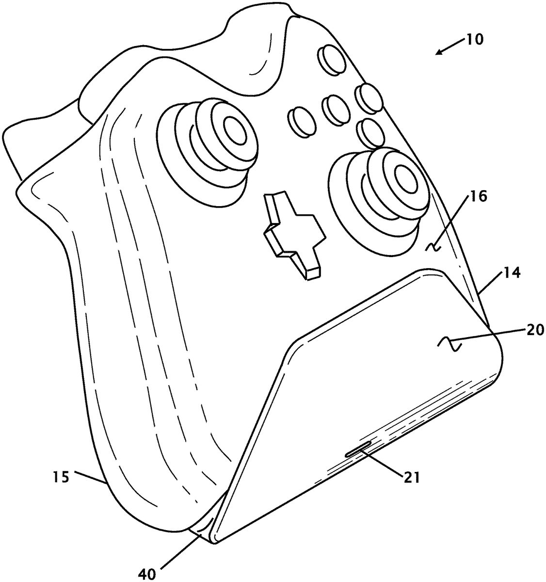
FIG. 1shows a perspective view of the remote control stand10with a game controller16retained within the remote control stand10. While this figure may show a particular wireless game controller, the game controller16can take a different visual appearance and the retainer or stand is configured to accommodate the particular geometry of the wired or wireless controller16. In this preferred embodiment the remote control stand10has a removable/replaceable face plate20on the base housing40. The face plate20has a charge indicator21. The charge indicator21can show different colors and/or can flash to show the charging status of the remote and/or the remote control stand10.
The game controller has two separate hand grips14and15and the stand supports the game controller16by retaining the game controller16between the two separate hand grips14and15. When the game controller16is placed into the remote control stand10the stand provides an enlarged grip area for the game controller16that allows a user to safely hold the game controller16without fear of activating the buttons and controls as the person lifts the holder and game controller and sets the holder and game controller down as a single unit. The stand does not restrict use of the functions of the game controller. A user can use the game controller while the game controller is installed on the stand while the stand is sitting on a table, desk or other surface. Game controllers16generally have curved surfaces to conform to the hand or hands of a user. Because the surfaces are curved, activation of a button while the game controller is sitting on a curved housing will cause the controller to rock on the curved surface and thereby making the controller unstable.
FIG. 2shows a rear perspective view of the remote control stand10andFIG. 3shows a front perspective view of the remote control stand10. These views show the remote control stand10with the faceplate20installed. The face plate20can be custom printed and/or embossed to reflect a particular game or gaming system. Due to the variety of games and gaming systems along with the continuous release of new games the face plate20can be customized and installed onto the remote control stand10prior to shipment. It allows the manufacturer the ability to stock the base stand and either a variety of different face plates20or to print the faceplate just prior to placing the remote control stand10into a box for shipment. The face plate20“snaps” or is otherwise secured to the base housing40. The connection mechanism is shown and further described in other figures herein.
When a remote control (not shown in these figures) is installed on the remote control stand10the handles straddle the grip saddles59on opposing sides of the remote control stand10. With the remote control installed the remote control has electrical contacts that contact the charging contacts43. These charging contacts43will recharge batteries within the remote control and can also provide power to the remote control while the remote control is properly installed on the remote control stand10. Electrical power is supplied to the remote control stand10through a power socket41that is locate on the back of the remote control stand10. The remote control stand10also has some internal power supply that allows the remote control stand10to power a remote control with or without external power being supplied to the remote control stand10.
When power is supplied to the remote control stand10a charge indicator21is illuminated. The charge indicator21can have a variety of colors and/or can flash to indicate the charging status of the remote control stand10and/or the remote control. The base housing40is shown with a plurality of cooling holes42or openings that allows for cooling or heat build-up of internal electronics.
FIG. 4shows a front plan view of the remote control stand10andFIG. 5shows a side sectional view of the remote control stand10cut through section5-5fromFIG. 4. The cross-sectional view shows the internal structure and the securing mechanisms that hold the face plate20onto the front of the base housing40. In general, the face plate20is retained on the base housing40with a plurality of hooks22that engage on tabs44. While this figure shows a single hook22and tab44, other figures shows the plurality of these components to secure the face plate20.
In these figures the charging contacts43are shown of the upper rear of the remote control stand10. These charging contacts connect to a remote control (not shown in this figure) to charge and power the remote control. When the remote control is properly seated on the remote control stand10the remote control will sit on the saddle58and rest against the contacts45. The charging indicator21is an extension of the lens30and extends through the face plate20to provide a visible indicator of charging and/or a charge status of the remote control and/or the internal power storage80in the bottom of the remote control stand10.
The internal power storage80is a power pack or batteries and is retained in a storage housing81that is mounted or otherwise secured to the base housing40. A PCB60is secured to the storage housing81. The PCB60has the connector45for receiving external power through the power socket41through a rear housing70. The connector45is on a connector plate49and can be changed or altered for different connector45locations or types. The PCB60conditions power from the external power, connects to the connector45, handles power to and from the power storage80and provides illumination to the charge indicator21. Cooling holes42in the rear housing70allow for some air movement through the remote control stand10to vent heat that may be created in the remote control stand10by the PCB and/or the power storage80.
FIG. 6shows a front perspective view of the remote control stand10with the face plate20displaced. From this view the grip saddle(s)59are clearly shown on the sides of the base housing40. This figure shows the charging indicator21proudly extending out from a front face46of the base housing40. The charge indicator21extends into and through an indicator opening24where the front of the charge indicator21is essentially flush with the outer face of the face plate20. The front face46has a plurality of round centering openings47and a plurality of rectangular openings. In other figures the complementary features on the rear of the face plate20are shown and described to engage and secure the face plate20onto the based housing40. The round centering openings47ensure proper alignment of the hooks22on the tabs44.
FIG. 7shows a rear perspective view of the remote control stand10with the rear housing removed. This figure shows the internal structure and the securing mechanisms that hold the face plate20onto the front of the base housing40. In general, the face plate20is retained on the base housing40with a plurality of hooks22that engage on tabs44. The hook(s)22pass through rectangular opening(s)48. While this figure shows a single hook22and tab44, other figures shows the plurality of these components to secure the face plate20. Some of the hooks and tabs are obscured by the saddle58of the base housing40, round centering opening47and the storage housing81.
In these figures the charging contacts43are shown of the upper rear of the remote control stand10. These charging contacts43connect to a remote control (not shown in this figure) to charge and power the remote control. The lens30extends through base housing40and the face plate20to provide a visible indicator of charging and/or a charge status of the remote control and/or the internal power storage in the storage housing81in the bottom of the remote control stand10.
The PCB60is secured to the storage housing81. The PCB60has the connector45for receiving external power through the power socket41through a rear housing70. The connector45is on a connector plate49and can be changed or altered for different connector45locations or types. A connector PCB50connects to the main PCB60and to the connector(s)45. The main PCB60conditions power from the external power, connects to the connector45, handles power to and from the power storage80and provides illumination to the charge indicator21.
FIG. 8shows a rear perspective view of the remote control stand10with the face plate20displaced and the indicator light lens30andFIG. 9shows a rear perspective view of the remote control stand10with the face plate20installed on the base housing40. Starting with the face plate20, the indicator opening24is shown as an open oval. The rear of the face plate20has a plurality of centering boss25cruciforms that locate the face plate20with the centering bosses25passing into the centering round openings47. The rear of the face plate20further shows a plurality flex arms23with hooks22. The flexible flex arms23and hooks22pass through rectangular openings48in the base housing40. The flexible arm bends to snap around the tabs44. The flex arm(s)23can be bent to remove the faceplate20from the base housing40. The hooks22are configured to “hook” “snap” or otherwise engage onto the tabs44. There are a total of six hooks22and tabs44, but there could be as few as one, two, 4, 6 or more. In the figures you can see that some of the hooks22are arranged in a mirror image to lock the tabs44in opposite directions.
The lens30passes through the lens opening52in the base housing40and then through the indicator opening24in the face plate20. While an oval indicator opening24is shown and described, other shapes are contemplated including illuminating all or a portion of the face plate. An LED or other illumination device sends illumination into the lens top31to illuminate the lens30and the illumination is visible on the charger indicator. A plurality of studs51that are adjacent to the lens opening52are for securing the lens30to the base housing40and are heat staked or otherwise deformed to retain the lens30onto the inside of the base housing40.
Thus, specific embodiments of a holder for a game controller have been disclosed. It should be apparent, however, to those skilled in the art that many more modifications besides those described are possible without departing from the inventive concepts herein. The inventive subject matter, therefore, is not to be restricted except in the spirit of the appended claims.
SEQUENCE LISTING
Not Applicable.
Claims
- A remote control stand for a game controller comprising: a support structure having at least one pocket that supports at least one game controller;said support structure includes a connection that provides electrical power and/or charging to said at least one game controller;said support structure includes a base housing and a separate face plate;said separate face plate being configured to be secured to said base housing with a securing mechanism;said base further includes a charge indicator having a lens that extends from within said base housing through said base housing and said separate face plate;said securing mechanism includes at least one hook and at least one tab, and said base housing includes at least one connector that receives electrical power from an external power source.
- The remote control stand for a game controller according to claim 1 , wherein said separate face plate includes indicia.
- The remote control stand for a game controller according to claim 1 , wherein said support structure does not restrict use of controls on said at least one game controller when said at least one game controller is seated in said support structure.
- The remote control stand for a game controller according to claim 1 , wherein said support structure supports said game controller by retaining said game controller between two separated hand grips.
- The remote control stand for a game controller according to claim 1 , further includes an internal chargeable power source.
- The remote control stand for a game controller according to claim 5 , wherein said internal chargeable power source is configured to power and or charge said at least one game controller.
- The remote control stand for a game controller according to claim 1 , wherein said charge indicator has more than one color and/or flashes.
- The remote control stand for a game controller according to claim 1 , wherein said base housing has at least two centering openings.
- The remote control stand for a game controller according to claim 8 , wherein said separate face plate has at least to centering bosses that are configured to mate with said at least two centering openings in said base housing.
- The remote control stand for a game controller according to claim 1 , wherein said base housing has at least two openings that are configured to receive said securing mechanisms from said separate face plate.
- The remote control stand for a game controller according to claim 1 , wherein said separate face plate has at least one flexible arm with said at least one hook that is configured to secure said separate face plate on said base housing.
- The remote control stand for a game controller according to claim 11 , wherein there are at least two flexible arms, with each flexible arm having a hook.
- The remote control stand for a game controller according to claim 11 , wherein there are at least 4 flexible arms, with each flexible arm having a hook.
- The remote control stand for a game controller according to claim 11 , wherein there are 6 flexible arms, with each flexible arm having a hook.
- The remote control stand for a game controller according to claim 1 , wherein said base housing further includes a power storage device.
- The remote control stand for a game controller according to claim 15 , wherein said power storage device is connected to said connection that provides electrical power and/or charging to said at least one game controller.
- The remote control stand for a game controller according to claim 1 , further includes a rear housing with cooling openings.
Disclaimer: Data collected from the USPTO and may be malformed, incomplete, and/or otherwise inaccurate.