U.S. Pat. No. 11,207,599
GAMEPLAY SYSTEM WITH PLAY AUGMENTED BY MERCHANDISE
AssigneeDisney Enterprises, Inc.
Issue DateFebruary 26, 2020
Illustrative Figure
Abstract
A gameplay system for providing interactivity based on a piece of merchandise or other object held or worn by a player. Th system includes an object identification assembly, which may be a modified computer vision system, that operates to sense, for a gameplay participant, the presence and identity of a particular augmenting object such as themed merchandise worn or held by a rider of a theme park ride. The sensing may be performed by detecting an on-and-off pattern of light emitted from the object. In response, the gameplay system selects or modifies the interactive features of gameplay associated with the participant based on the identified augmenting object. For example, the interactive features are selected from memory by the gameplay system controller to match a character associated with the augmenting object during any interactive gameplay. This allows the gameplay participant to choose their abilities or powers for gameplay.
Description
DETAILED DESCRIPTION Embodiments described herein are directed toward a gameplay (or other interactive) system configured to provide enhanced individualized interactivity for each player or participant. The gameplay system includes a plurality of augmenting objects, such as pieces of themed merchandise, and each has associated with it an identifier and a set of interactive features or functionalities. The gameplay system includes an object identification (or detection) assembly configured to sense the presence of one (or more) of the augmenting objects in a gameplay space and to determine the identity (or identifier) of the sensed augmenting object. In response, a game controller generates or modifies interactive features of the gameplay provided to a participant associated with the sensed augmenting object to create a unique interactive experience for the participant. In one particular implementation, the new gameplay system may be implemented at an amusement or theme park in one of its rides or attractions designed for interactivity (e.g., with vehicle riders). The regular gameplay experience is augmented or enhanced/modified by allowing participants such as vehicle riders to wear (or hold) augmenting objects or themed merchandise, which may be purchased onsite or offsite (e.g., online or a physical offsite store). One particular use case recognizes that characters such as superheroes often wear objects in the form of “power gauntlets” that can be activated to provide superhero-type abilities (e.g., shoot out weapons), and these power gauntlets may include a wristband or glove with a themed outer covering or body to be worn on the participants wrist or hand (and often extend over the wrist). In practice, participants that may be vehicle riders may be provided new interactive features or functions. For example, the participants wearing a power gauntlet may experience new visual types of projectiles rendered from the perspective of their wrist (or other portion ...
DETAILED DESCRIPTION
Embodiments described herein are directed toward a gameplay (or other interactive) system configured to provide enhanced individualized interactivity for each player or participant. The gameplay system includes a plurality of augmenting objects, such as pieces of themed merchandise, and each has associated with it an identifier and a set of interactive features or functionalities. The gameplay system includes an object identification (or detection) assembly configured to sense the presence of one (or more) of the augmenting objects in a gameplay space and to determine the identity (or identifier) of the sensed augmenting object. In response, a game controller generates or modifies interactive features of the gameplay provided to a participant associated with the sensed augmenting object to create a unique interactive experience for the participant.
In one particular implementation, the new gameplay system may be implemented at an amusement or theme park in one of its rides or attractions designed for interactivity (e.g., with vehicle riders). The regular gameplay experience is augmented or enhanced/modified by allowing participants such as vehicle riders to wear (or hold) augmenting objects or themed merchandise, which may be purchased onsite or offsite (e.g., online or a physical offsite store). One particular use case recognizes that characters such as superheroes often wear objects in the form of “power gauntlets” that can be activated to provide superhero-type abilities (e.g., shoot out weapons), and these power gauntlets may include a wristband or glove with a themed outer covering or body to be worn on the participants wrist or hand (and often extend over the wrist).
In practice, participants that may be vehicle riders may be provided new interactive features or functions. For example, the participants wearing a power gauntlet may experience new visual types of projectiles rendered from the perspective of their wrist (or other portion of the body where object is worn), e.g., projectiles rendered as if projected from the worn augmenting object. In some cases, the participants will also see that their projectiles, which were provided based on an identification of the power gauntlet they are wearing/holding, have a unique impact on the virtual projected environment or AR portion of the interactive experience that differs from other impacts associated with projectiles or other augmenting features/functionalities associated with other power gauntlets and with interactions provided to those not wearing or holding any augmenting object. Stated differently, certain “powers” are given to those with the power gauntlets by the gameplay system and will provide unique opportunities to affect the nearby physical or displayed scenic environment such as by unlocking different events as part of an interactive game. In other cases, though, the gameplay system may extend outside a venue setting and allow the user of the augmenting object to role play at home, on a cruise ship, or other environment and, in some cases, to connect with other experiences like console and/or online games.
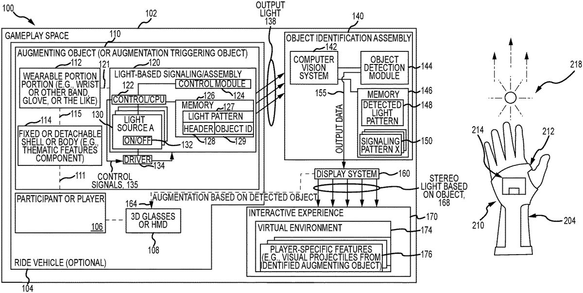
FIG. 1is a functional block drawing of a gameplay system (which can mean nearly any interactive system)100to provide personalized interaction for participants106based on use and detection of an augmentation triggering object (e.g., particular merchandise or a toy linked to the game)110of the present description. The system100includes a gameplay or interactive space102, which in the example of a park ride or attraction may be a space along a vehicle's ride path or a space in which visitors of the park enter to participate in gameplay. As shown, a human participant or player106has entered the space102, and, in a typical system100, there would be one, two, three, or more participants106.
The participant or player106may enter the space102on foot or may be brought into the space102in or on a ride vehicle104. The participant106may be wearing equipment to support a 3D virtual or augmented reality (VR or AR) display system160providing signals164such as by wearing 3D glasses or an HMD108. The signals164are used to provide an individualized interactive experience to the participant106by augmenting their interactive experience170in a manner based on whether or not they are wearing or holding an augmenting object110and based on an identification of the object110(e.g., what piece of merchandise is it and what “powers” or functions are associated with it for the particular interactive experience170provided in the gameplay space102by the system100). In other cases, though, the participant106may not wear any 3D headgear108and be provided the interactive experience including 3D visuals unique to them and their augmenting object110by having the display system160adapted for autostereoscopic projection or display via its output light168providing left and right eye images for the participant106at their present eye locations. The type of display system160used may vary to implement the gameplay system100as long as it is configured to provide audio and/or visual components that are linked to identification of the augmenting object110and associating it with the participant106so that the participant106perceives the interactive experience as being affected by their wearing or holding the augmenting object110.
In the system100, the participant106is shown with dashed line111to be wearing or holding an augmenting object (or augmentation-triggering object)110. This object110may take a wide variety of forms including, but not limited to, toys or clothing articles or nearly any pieces of merchandise that a participant106may hold or wear such as on their hands, wrists, arms, heads, or other portions of their bodies (e.g., gloves or bands for fitting over a portion of a person's hands, an item that can be held on a person's arms with a wrist or arm band, a hat, a shirt, coat, uniform, vest, or the like). As shown, the object110includes a base portion112that typically will be wearable such as a wrist, arm, or hand band configured to retain the object110on the body of the participant106, and the object110further may include a shell or body114that may be fixed onto the base112or be detachable (both attachment types shown by dashed line115). The shell or body114may take nearly any form with some embodiments using it to provide thematic features to the object110such as to take on the appearance of articles of clothing, tools, or weapons associated with characters from media (e.g., a superhero moving character, a character from a children's animated feature, and so on). In some of the specific examples provided herein, the augmenting object110, with its wearable portion112and shell/body114, is designed to take on the appearance of a power gauntlet, but, with this example in mind, those skilled in the arts will readily understand that the object110may be nearly any item that the public associates with characters from their favorite media or characters often associated with gameplay (e.g., from role play and so on).
The system100includes an object identification assembly140that is adapted to detect the presence of the augmenting object110in the space102(and associate it with participant106) and to identify the detected object110(e.g., which type of power gauntlet is the participant106wearing from a set of two or more differing types?). The assembly140may be wholly or partially located onboard the vehicle104in some embodiments. The assembly140is also preferably adapted to determine where on the participant's body the object110is worn or otherwise located such as on which wrist or hand as this will allow the display system160to create visual augmentations or features176to the interactive experience170that are more realistic as they appear to emanate from or to be projected from that portion of the body or the location of the object110in the gameplay space102. This may also be useful it the participant106is wearing or holding more than one object110such as one on each of their wrists, hands, or arms (and each may be different to provide two (or more) differing or matching augmentations or interactive features176per player106during operations of the system100). The detection method implemented by the assembly140preferably is automatic and will not require the participant106to take any action (possibly other than powering on their object110) such as a special registration or tagging to hardware of the system100. Object detection is, in this way, more interesting and magical.
To this end, the augmenting object110further is shown to include a light-based signaling assembly120that is mounted upon or in the wearable or base portion112as shown with dashed line121. Other implementations, though, provide the assembly120on or in the shell or body114. The assembly120is adapted to generate or emit output light138in a manner that acts to provide a signal to the object identification assembly140, which it can process to detect and identify the augmenting object110in the space102. The assembly120includes a controller or processor122that manages operations of a control module124and memory (or data storage)126. The memory127stores a light pattern or signal definition127, which may take the form of a header128and an object identification129. In some embodiments, the output light138may be a series of flashes of light timed with the sampling frequency of the assembly140to communicate the bits of the header128and the bits of the object ID129, and the header128may be used to identify the presence of one of the augmenting objects110(e.g., to indicate presence of a power gauntlet) while the object ID129indicates the particular type of object110(e.g., to indicate a particular piece of merchandise such as a specific power gauntlet).
The control module124may take the form of software and/or firmware124to provide the control functions described herein. The module124may include wireless communication devices to allow the assembly120to communicate with the object identification assembly140such as to receive a command or ping to initiate operations to provide the output light138(e.g., the object110may not provide the light signal or output138until interrogated by the assembly140in some cases). The light-based signaling assembly120includes one or more light sources130and a driver (e.g., a self-contained power supply or the like)134, and each of the sources130may respond to control signals135from the controller122to provide the output light138in the defined light pattern127(i.e., to signal a header128and an ID129) by alternating between on and off states132.
In one embodiment, the light sources130are each light emitting diodes (LEDs) that in some cases are infrared (IR) LEDs so that the output light138is not visible to the participant106so as to make the detection and identification by the object identification assembly140more magical or behind-the-scenes for the participant106. The use of two, three, or more light sources130operating based on the same light pattern127is desirable in some cases to increase the likelihood that the output light138is detected by the assembly140(e.g., is not blocked by portions of the player's body, by the vehicle104, by other participants106, and the like), and, typically, two or more sources130are used that are spaced apart some distance from each other on the base112. The shell or body114is configured to allow the light138from sources130to pass such as with windows transparent or transmissive to the light138or by being formed of a material that allows the light138to be transmitted through the shell or body114.
As shown, the object identification assembly140includes a computer vision system142that runs an object detection module144(e.g., software providing algorithms and/or machine learning processes). The assembly140further includes memory/data storage146storing a detected light pattern148from the output light138from the object110and a set of one-to-many signaling patterns150. The object detection module144works to compare detected light patterns148with the signaling patterns150to identify likely matches. Each signaling pattern150is associated with a particular augmenting object type (e.g., a particular piece of merchandise such as a power gauntlet for a character from a movie). The computer vision system142may take any form now understood in the arts or to be later developed, and it basically operates to capture video images of the space102including the participant106and any augmenting object110present.
In some embodiments, the computer vision system142operates to process these images to identify the presence and location of the participant106and then operates with the object detection module144to monitor for the presence of the output light138. The output light138is then processed to find a match among the patterns150. The module144or another element of the assembly140communicates this match or output data155to the display system160. The output data155may include a location of the object110within the space102(e.g., within the vehicle104) and on or near the body of the participant106. The output date155also will identify the augmenting object110to the display system160. The display system160uses this information to generate (e.g., render) player-specific features176in the virtual environment174provided as part of the interactive experience170in the space102. For example, the display system160may render 3D imagery (signals164or light168) that produces visual projectiles176that appear to emanate or to be projected from the augmenting object110, and the projectiles176may be rendered to suit or match the type or ID of the augmenting object110and may differ for each type or ID of object110(e.g., to suit the abilities or powers of the character associated with the augmenting object such as the superhero associated with a power gauntlet or the like).
FIGS. 2A-2Cillustrate a top view and top perspective views, respectfully, of a participant wearing an augmenting object (as would be useful in the system100ofFIG. 1as augmenting object110) in the form of three differently themed power gauntlets210,230, and240and showing their use after identification to differently augment an interactive gameplay environment. As shown inFIG. 2A, a player204is using power gauntlet210, and they are wearing the power gauntlet210on their left hand (with portions extending over their left wrist). The gauntlet210includes a base portion212that is wearable as it includes an elastic (or Velcro-type) band212that extends around the body of the hand of the user204between the forefinger and thumb, and the base portion212retains the gauntlet210upon the player's hand. The power gauntlet210also includes a shell or body214that may be detachable from the base212or be more rigidly attached, and the shell or body214provides thematic features or elements such that the gauntlet210takes a form matching a gauntlet worn by a character (e.g., on from some form of media such as a superhero from a moving, a villain or hero from a computer or video game, and the like).
A light-based signaling assembly such as assembly120would be provided on or in the gauntlet210such as on the base portion212and is hidden from the view of the player204by the shell or body214(and, hence, is not shown inFIG. 2A). During use in gameplay as shown inFIG. 2A, an object identification assembly (such as assembly140) operates to monitor a gameplay space for the presence of the gauntlet210(and gauntlets230and240) using a computer vision system (such as system142ofFIG. 1). When detected and identified (e.g., gauntlet “X” associated with character “Y”), the object identification assembly provides this information or data to a display system to augment or modify an interactive experience in a manner matched to the particular power gauntlet210. As shown, the augmentation is specific to the gauntlet210and includes rendering and displaying a stream of fireballs (or similar projectiles)218to the player204as part of an interactive experience. The augmentation is player-specific in that the visual features218are shown to the player204with the gauntlet210(or the left hand or wrist of the player204) as being the source of the projectiles/visual features218, and the direction of the stream of virtual projectiles218may be set by the display system based on output data from the computer vision system including the orientation and/or pose of the wrist and/or hand of the player204in the gameplay space.
As shown inFIG. 2B, a second or different player220is wearing a second power gauntlet230that differs from the first gauntlet210. The second gauntlet230includes a base or base portion232in the form of a wrist band so it can be worn by the player220on their wrist (here shown to be the player's left wrist). A shell or body234is attached (in a fixed or detachable manner) to the base portion232and is used to provide a different set of thematic features to the gauntlet230when compared to the gauntlet210and also to disguise and hide from view a light-based signaling assembly (which may be on the base portion232(or on an interior surface or portion of the body or shell234).
During use, the light-based signaling assembly may be turned on by the player220(or turn on automatically in response to signals from an object identification assembly) and operate to generate a signal specific to the gauntlet (or type of gauntlet) that allows the object identification assembly to detect presence of a gauntlet (gauntlets210,230, and240may provide a signal with a similar or standard header in some embodiments) and also to determine its ID or type. When detected, the object identification assembly passes the location of the gauntlet230(or the hand/wrist of the player220) to a display system to generate a visual (and, in some cases, audio) augmentation to an interactive experience that is matched or linked to the type or ID of the gauntlet230, and it is shown here inFIG. 2Bto differ from the gauntlet210such as disks or other solid-type projectiles238.
FIG. 2Cshows a third example of a power gauntlet250that is being worn by a player/user240. The gauntlet250includes a base portion or base252in the form of an article of clothing that extends over and wraps around the wrist and provides a partial or full glove over the player's hand. A shell or body254is supported upon the base252to provide it thematic features differing from gauntlets210and230and, as discussed above, to hide the presence of a light-based signaling assembly. During use, an object identification assembly detects the presence of a gauntlet in a gameplay area, and it identifies the ID and/or type for the gauntlet250. This information along with the location of the object250and/or hand/wrist of the player240is passed to a display system, which renders an augmentation suited to the ID and/or type of the gauntlet250, and this augmentation258(e.g., energy rays or lasers or another projectile differing from those provided for gauntlets210and230) is displayed (or played if audio) to the viewer240in the gameplay space as if being emitted from the power gauntlet250(or the player's hand and/or wrist).
FIG. 3illustrates the augmenting object (e.g., power gauntlet or similar piece of merchandise)210ofFIG. 2Awith the body or shell214removed to show portions of a light-based signaling assembly (e.g., an implementation of the assembly120ofFIG. 1) operating to facilitate detection and identification of the augmenting object210. In this embodiment, the light-based signaling assembly includes three IR LEDs370that are spaced apart from each other in a triangular pattern so that they emit light (shown to be “ON” inFIG. 3) outward from the top of the hand of the player210(when worn as shown inFIGS. 2A and 3). A different pattern may be used in some cases such as a straight line, and other embodiments may use fewer or more light sources with three being a useful number to enhance the likelihood that at least one of them will be detected by a computer vision system processing images of a player wearing the gauntlet210. The light-based signaling system is shown to also include a controller380for generating operating or control signals to “play” a signal pattern assigned to the gauntlet210(continuously or in response to an interrogation or ping from the object identification assembly). Additionally, one (or more) LED drivers390are provided to provide appropriate power concurrently to the LEDs370(for concurrent ON/OFF operations based on the assigned light or signal pattern).
FIG. 4is a flow diagram of a method400for providing object-based augmentation of an interactive experience including algorithms for object detection using computer vision and machine learning, and the method400may be carried out by operations of the system100and using the power gauntlets210,230, and240ofFIGS. 2A-2C. The method400starts at405such as with defining a signal or lighting pattern to be assigned to each augmenting object (e.g., to each piece of merchandise or toy or other object) to be used in a particular gameplay or other interactive experience and with choosing an augmentation for the interactive experience to assign to that object when it is identified as being present and/or being used by a player. Each of the augmentations may then be provided in a gameplay controller or display system to allow it to be provided upon detection of the matching object.
The lighting patterns may vary to practice the method400, but it may be useful to describe one useful prototype that was designed and used to show that detection of power gauntlets can be successfully performed. The patterns were encoded in 28 bits with a standard 8-bit header used to determine where the pattern begins and a unique 20-bit code to specify an object's unique identifier. The number of bits in the pattern and the sampling detection frequency define the maximum number of codes/patterns read per second by an object identification assembly or other detection device. In one embodiment, the sampling detection frequency was set at 60 frames/second (or 60 Hz) as it allows more differing patterns (e.g., more unique objects) but other embodiments may use a lower frequency. These variables may be varied to implement the method400to allow for either more patterns by using a higher frequency or for a lower sampling frequency by using fewer bits in the assigned codes/patterns.
The method400continues at410with providing participants or players with augmenting objects each adapted for displaying one of the assigned signals/codes with their light-based signaling assemblies. For example, there may be ten differing objects (or ten different types of objects each associated with a particular character or set of abilities/functionalities or “powers”) that will be used for one interactive experience, and ten differing codes/signal patterns will be created and assigned to each object of the differing types. Step410may involve each of the players purchasing their own augmenting objects (e.g., each may be merchandise available at a theme park or other interactive gaming venue or available at other stores (online or brick and mortar)) or the objects may be provided free for use to each player (e.g., at the start of a ride or other interactive experience). In either example, the players may be informed that they may wish to choose merchandise due to its abilities to provide or alter their gameplay abilities in particular interactive experiences (e.g., if you want the powers of superhero “X” consider obtaining merchandise “Z”). At step420, the players may wear or hold their augmenting objects and place them in a powered-on mode (or this may be performed automatically in response to external control signals in some cases).
At step430, the method400continues with operating the object identification assembly to capture images of players in the gameplay space near where an interactive experience is being provided. In one example, this involves a computer vision system operating within a ride vehicle to capture images of the vehicle's riders when the vehicle has entered or stopped at or in a portion of the ride path involving an interactive experience. The method400continues at440with segmenting the image data to identify a region or portion of the player's body associated with an expected location of an augmenting object. For example, the object may be designed for wearing on a player's right or left wrist or hand, and step440may involve generating a set of skeletal data for a player and then segmenting the player's two wrists (e.g., draw a box or boundary around the portion of the image including the two player's wrists). Machine learning or other processes may be used on this segment to identify whether or not an augmenting object is present as this significantly reduces processing by reducing the number of pixels to be processed or searched for a matching pattern (which increases performance by reducing the time to process) and reduces the number of possible false positives (which allows the machine learning to ignore spurious flashes or other noise elsewhere in the image for improved accuracy).
In step450, the method400involves the object detection module processing the segment of the image to determine whether or not there are any gauntlet present by looking for one or more light sources (e.g., IR LEDs) flashing a signal. If so, the module or its logic compares the sampled signal to see if it has an appropriate header and then whether it has a code or object ID matching one assigned to an augmenting object (e.g., a particular power gauntlet). If not, the method400continues at465with checking to see if the sampling period is over. If not, the method400continues at step430. To enhance accuracy, oversampling can be used by detecting patterns of light in the image data over multiple seconds (e.g., using a longer sampling period at465).
If a match is obtained in step450, the method400continues at460with storing the identified signal pattern for a particular player. If at465if the sampling period is over, the method400continues at470with determining whether the confidence value of the matched pattern(s) exceeds a minimum value. If not, the method400continues at430. If yes, then the method400continues at480. Step470may involve taking the modal value and comparing it with its outliers. The difference in occurrence count between them can be used to determine the confidence value of the matched pattern from step450.
In step480, the method400may involve outputting the ID of the detected augmenting object (e.g., the power gauntlet or the like) to a display system control. This control may use this ID to augment interaction with the player based on the presence and operation of the augmenting object (e.g., to output the correct identifying code or lighting signal). This augmentation may take nearly any useful form such as audio and/or visual modifications to standard interactivity visual effects (or even replacement of such conventional effects). This may include providing visual outputs such as projectiles or image streams from the determined object and its location into a gameplay space. The projectiles or image streams (or other augmentations to the interaction) are chosen and/or rendered by the display system to suit or match the particular augmenting object that was identified in the method400(as discussed above with reference toFIGS. 2A-2C, for example). The method400may continues at430or may end at490.
In some embodiments, anti-counterfeiting is provided in the method400by including a step in which an offboard device pings the gameplay space and any augmenting objects present to cause them to initiate or start flashing their identifying light-based signal. The ping signal may be specific to a particular object type so that the object identification assembly is only monitoring for particular objects in certain time periods. In this way, counterfeit objects are identified if they are transmitting their ID signals or codes during incorrect time periods.
The above embodiments are useful for explaining how an interactive gameplay experience (or other interactive experience) may be provided by a gameplay system of the present description to allow a user to choose how their experience is augmented by selecting which toy or piece of merchandise they bring with them into the interactive space (e.g., a theme park ride path, an AR or VR gameplay space, a home gaming system space, or the like). In other cases, though, it is desirable for a player or participant to be able to choose and/or modify operations of their toy or merchandise such as to have functions linked to or associated with a thematic element. Prior to this invention, toys and merchandise have been designed and manufactured to be single purpose with standalone functionality. Even “interactive” toys tend to allow the user to activate certain statically defined functions that are built into that toy. Hence, the inventors recognized a need for another gameplay system that includes merchandise or toys that can be dynamically extended in functionality by adding physical and functional customizations (which may take the form of thematic add-ons) to enhance interactivity and to provide the player/participant to have control over their gameplay.
To this end,FIG. 5illustrates a functional block diagram of an interactive gameplay system500adapted to allow a player (e.g., a buyer of merchandise) to select and/or modify (or upgrade) the thematic look of their toy and also its functionality during interactive gameplay (i.e., toy operations alone or with other toys). The system500includes a base toy510that may take many forms to implement the system500with a robot or “bot” being one (with “robot” intended to mean nearly any object with intelligence or logic to control and modify its operations and often with some form of locomotion that can also be modified or upgraded based on add-ons).
The base toy or merchandise510includes a physical body512for supporting its components. On the body512, the base toy510includes a processor514managing operations of input/output (I/O) devices516and memory522as well as running or executing code or software to provide the logic capabilities of a control program520. The I/O devices516may include transceivers for communicating, as shown with arrows552, with a remote control550operable by a player/participant to modify operations of the toy510and/or to receive updates on the operating status of the base toy510(e.g., remaining lives, score during gameplay, weapon availability, weapon power levels, and so on), which may be displayed on a display or GUI (not shown) on remote control550. The I/O devices516may also include components to facilitate interactive play in a more hidden or magical manner (e.g., without visibility to player operating remote control550) such as IR transmitter540and IR receiver542that may be used for “firing” upon other toys in interactive play and for detecting “hits” on itself during such gameplay.
The memory522is used to store a set of base operating functions524that may define operations or operating ranges for the components on the body512until an add-on element560is received (as discussed below). The control program520is configured to generate control signals, such as in response to inputs552from the remote control550, to an audio output assembly530providing sounds (stored in functions524) via one or more speakers, a light assembly532outputting light with colors, brightness, pulsing/timing patterns, and the like set in operating functions524, and a motion assembly536adapted to provide movement in one or more directions as shown by arrows537again that may be defined (e.g., with ranges) in base operating functions524.
Significantly, the system500further includes a plurality of add-on elements560that can be inserted mounted onto or inserted into the body512of the base toy510as shown with dashed line561. The mounting or inserting561is shown to be reversible, e.g., the add-on element560is detachable, so as to allow a player or owner of the system500to swap out the add-on elements560to achieve differing modifications and/or upgrades to the base operating functions524. This may be useful to change the thematic features of the toy510and to obtain functions associated with such themes (e.g., powers or functions associated with a particular character or species from movies, animated features, or other media or real-world environments).
As shown, each add-on element560is configured for the attachment561and may include a shell, cover, and/or faceplate562with (or without) thematic features. In such cases, the thematic component562may attach to an external surface of the body512such that it is visible during operations of the toy512. In other cases, the component562may simply take the form of or include a plug-in element (e.g., a USB device) that plugs into an I/O device516on the body512to facilitate communications or data transfer shown with dashed line565. Alternatively, the thematic component562such as a shell and/or faceplate may include such a communication device upon one of its interior/hidden surfaces.
Each add-on element560also includes memory or data storage564that is used to store a set of data568defining a set of expansion and/or upgrade operating functions568that are often unique or particular to which add-on element560is chosen from the two or more available in the system500(add-on thematic merchandise available for purchase for use with base toy510). These functions may modify base operating functions524such as to increase a speed, direction, or other operating range of the motion assembly536or may provide new operating functions for one or more toy component such as to provide new sounds for output with audio assembly530or differing lighting colors or patterns for lighting assembly532or new motions537for motion assembly536.
With this general understanding ofFIG. 5in hand, it may now be useful to provide one particular exemplary implementation of the interactive game system with base toy modifications/expansions. The exemplary implementation calls for the toy to take the form of a spider bot or spider-like robot. The add-on elements include multiple character-themed pieces of armor (e.g., faceplates) that go over a shell or other portion of the body of the base toy. Each includes memory/data storage defining a skill set (or operating functions for the base toy), and these may include lights and sound projection (e.g., to replicate laser or other weapon firing). In this implementation, the remote control has a display showing a life bar or life meter that drops during gameplay to reflect time of play and/or “hits” from opposing spider bots. The life meter allows the player to see “life” and/or assess “damage” from an attack. The display also shows a counter for use of the onboard weapons (e.g., a blaster counter).
The motion assembly is configured to provide movement of eight legs, which are geared and configured for spider-like movements. The input from the remote control can be used to control operations of the motion assembly to move the body forwards and backwards, to spin 360 degrees, to crouch down and stand up again. The base functionalities may include a set number of lives, and two battle modes using interactive IR technology that sends a one-way signal to “attack.” In this regard, an IR sender/transmitter may be provided in the front of the spider bot's body and an IR receiver in the back of the body. One base operating mode may be a heavy power attack (e.g., ultimate weapon mode with corresponding light and sound effects). Another base or expansion functionality may be projection of a shield to block for a predefined length of time an attack (such as laser shots provided by IR transmissions from another bot), and a recount time may be provided for when the shield may next be used. When lives are depleted, the bot may be controlled to have its motion assembly move it into a crouch and, in some cases, to eject a body part (e.g., a detachable shell that is configured to receive the add-on elements). Play can be reset with, as needed, reattachment of the ejected body part.
The add-on element may be configured to provide thematic and/or tactical upgrades for the spider bot. Upgrades change the performance and attributes of gameplay and may include additional functionalities or changes in ranges or parameters for: speed, lights, sounds, projection design, attack and shield powers, interactions between set characters and/or other bots, and the like. In some cases, the add-on elements may provide new operating functions that define the thematic or personality features of the bot and may be considered “a personality chip” as they provide the look and/or feel of the bot such as by changing the eye or skin color.
Although the invention has been described and illustrated with a certain degree of particularity, it is understood that the present disclosure has been made only by way of example, and that numerous changes in the combination and arrangement of parts can be resorted to by those skilled in the art without departing from the spirit and scope of the invention, as hereinafter claimed.
For example, system100was shown to include a display system160for providing an augmenting image168viewable by a participant106of an interactive experience170. However, other implementations of the system100may implement the display system160as an interactive system producing interactive or special effects that may or may not require a display screen and/or 3D devices to be experienced or enjoyed by the participant or player106. For example, the interactive effects may be augmented imagery and/or may be or include practical effects, audio effects, or other effects, and each or some of these may be selected or modified based on a determined identification of the augmenting object worn or held by the participant or player106.
Claims
- A system for providing augmented interactive experiences, comprising: a display system operating to present to a participant located in or proximate to a predefined space an image within an interactive experience;an augmenting object held or worn by the participant while in the predefined space, wherein the augmenting object includes a signaling assembly generating an output signal;and an object identification assembly processing the output signal to detect the augmenting object in the predefined space and to determine a location of the augmenting object in the predefined space, wherein the image presented by the display system is generated after the detection of the augmenting object by the object identification assembly and based on the location of the augmenting object, wherein the object identification system includes a computer vision system capturing an image of the predefined space including the participant, the augmenting object, and the output signal, wherein the output signal comprises output light from the augmenting object, wherein the output light comprises a pattern of light flashes at an output frequency, and wherein the object identification system includes an object identification module comparing the pattern of light flashes to a plurality of predefined signaling patterns to identify a matching one of the predefined signaling patterns.
- The system of claim 1 , wherein the processing of the output signal further includes determining an identification of the augmenting object and wherein the image is generated based on the identification of the augmenting object.
- The system of claim 1 , wherein the signaling assembly comprises one or more light sources operating to emit the pattern of light.
- The system of claim 3 , wherein the one or more light sources each comprise an infrared (IR) light emitting diode (LED).
- The system of claim 3 , wherein the one or more light sources comprise at least three LEDs mounted on a wearable base portion or shell portion of the augmenting object to be spaced apart a predefined distance from a neighboring one of the at least three LEDs.
- The system of claim 1 , wherein the object identification module processes the captured image to create a segment of the captured image that includes a portion of a body of the participant associated with the augmenting object and then processes the segment to detect the pattern of light flashes.
- The system of claim 1 , wherein the captured image comprises video of the space gathered over a time period defined to provide oversampling in detecting the pattern of light flashes and wherein the object identification module implements a sampling frequency of at least 30 Hz.
- The system of claim 1 , wherein the output signal comprises a header defining a start point of a signal followed by a message body defining an identifier for the augmenting object and wherein the object identification assembly processes the identifier in an output signal to determine a type of merchandise associated with the augmenting object.
- The system of claim 1 , wherein the object identification assembly transmits an interrogation signal and wherein the signaling assembly of the augmenting object initiates generating the output signal after receipt of the interrogation signal.
- A system for providing augmented interactive experiences, comprising: an interactive system providing an interactive effect to a participant of an interactive experience;an object held or worn by the participant, wherein the object includes a light-based signaling assembly generating output light in a signaling light pattern;and an object identification assembly processing a captured image of a space including an imagery of the participant, the object, and the output light to detect the object in the space, wherein the signaling light pattern includes encoded information including an identifier for the object as being a specific one of a plurality of differing objects, and wherein the interactive system generates the interactive effect based on the identifier for the object and wherein each of the plurality of differing objects is associated with a differing set of interactive effects.
- The system of claim 10 , wherein the object identification system includes a computer vision system obtaining and processing the captured image, wherein the signaling light pattern is a pattern of intermittent light flashes, and wherein the object identification system includes logic for comparing the pattern of light flashes to a plurality of predefined signaling patterns to identify a matching one of the predefined signaling patterns.
- The system of claim 11 , wherein light-based signaling assembly includes one or more light sources each comprising an infrared (IR) light emitting diode (LED).
- The system of claim 11 , wherein the logic is adapted to process the captured image to create a segment of the captured image that includes a portion of a body of the participant associated with the object and then processes the segment to detect the pattern of light flashes.
- A system for providing player-selected interactive functionalities, comprising: a base toy comprising memory storing a set of base operating functions, a body, a set of operational elements mounted upon the body, and a controller operating the set of operational elements to operate to provide one or more of the set of base operating functions;and an add-on element detachably mounted upon the body, wherein the add-on element comprises memory storing a set of upgrade operating functions, wherein the controller further operates the set of operational elements to operate to provide one or more of the set of upgrade operating functions, wherein set of base operating functions includes attacking modes, defensive modes, and life parameters for use in interactive gameplay, and wherein the set of upgrade operating functions modifies or adds to at least one of the attacking modes, the defensive modes, and the life parameters.
- The system of claim 14 , wherein the add-on element comprises a thematic component configured for mounting to an external surface of the body of the base toy and wherein the thematic component includes the memory adapted for being communicatively linked to the controller of the base toy.
- The system of claim 14 , wherein the set of operational elements includes a motion assembly for moving the body of the base toy, wherein the set of base operating functions includes a speed range for the moving of the body or a set of locomotion types for the body, and wherein the set of upgrade operating functions modifies the speed range or modifies or adds to the set of locomotion types.
- The system of claim 14 , wherein the set of operational elements includes a sound assembly and a light assembly, wherein the set of base operating functions includes a set of sounds for output by the sound assembly and a set of lighting parameters for use in operating the light assembly, and wherein the set of upgrade operating functions modifies or adds to at least one of the set of sounds and the set of lighting parameters.
Disclaimer: Data collected from the USPTO and may be malformed, incomplete, and/or otherwise inaccurate.