U.S. Pat. No. 11,207,590
VIDEO GAME CONTROLLER
AssigneePerformance Designed Products LLC
Issue DateAugust 20, 2020
Illustrative Figure
Abstract
A video game controller can automatically operate as a video game controller with audio capability and a video game controller without audio capability based upon a signal received via a switch in communication with an audio jack of the video game controller when a headset is coupled to the audio jack. Connection of the headset to the controller automatically causes video game audio to be communicated from the video game console to the headset via the controller. The video game audio is communicated at a default volume level to the headset upon coupling of the headset to the video game controller. The volume level of the audio communicated to the headset can be adjustable up or down via a directional pad of the video game controller while an audio control button on the video game controller is pressed.
Description
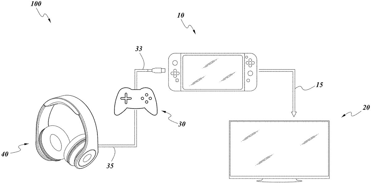
DETAILED DESCRIPTION FIG. 1shows a schematic diagram of a video game system100. The video game system100can include a video game console10. In the illustrated embodiment, the video game console10is a NINTENDO® Switch™ console. The video game console10can optionally be connected to a television or video monitor20(e.g., via a cable15, such as HDMI cable). A video game controller30can optionally be removably connected to the video game console10(e.g., via a cable33). Optionally, a headset40can be removably connected to the video game controller30(e.g., via a cable35, such as a USB cable). The video game controller30can have one or more control inputs, such as thumbsticks, directional pads, buttons (e.g., A/B/X/Y buttons), paddles, triggers, etc., to effect different functionalities while playing a video game on the video game console10. Though not shown, the video game controller30has a connector that removably receives a connector (e.g., USB connector) of the cable35to connect the headset40to the video game controller30. Though not shown, the video game controller30has a connector that removably receives a connector of the cable33to connect the video game controller30to the video game console10. FIG. 2shows a firmware control process200implemented by the video game controller30(e.g., by the MCU of the controller30) based on whether the headset40is connected to the video game controller30. The method includes the step of detecting210if the headset40is connected to the controller30(e.g., if an audio jack of the controller30has received the connector of the cable35attached to the headset40). If the headset connection is not detected, then USB gamepad descriptors (e.g., to enable playing the video game with the control inputs of the controller30) are automatically selected230. Alternatively, if the headset connection is detected, then USB descriptors for audio and gamepad composite device (e.g., to enable playing the video game with the control inputs of the controller30as well as enable audio transfer from the console10via ...
DETAILED DESCRIPTION
FIG. 1shows a schematic diagram of a video game system100. The video game system100can include a video game console10. In the illustrated embodiment, the video game console10is a NINTENDO® Switch™ console. The video game console10can optionally be connected to a television or video monitor20(e.g., via a cable15, such as HDMI cable). A video game controller30can optionally be removably connected to the video game console10(e.g., via a cable33). Optionally, a headset40can be removably connected to the video game controller30(e.g., via a cable35, such as a USB cable).
The video game controller30can have one or more control inputs, such as thumbsticks, directional pads, buttons (e.g., A/B/X/Y buttons), paddles, triggers, etc., to effect different functionalities while playing a video game on the video game console10. Though not shown, the video game controller30has a connector that removably receives a connector (e.g., USB connector) of the cable35to connect the headset40to the video game controller30. Though not shown, the video game controller30has a connector that removably receives a connector of the cable33to connect the video game controller30to the video game console10.
FIG. 2shows a firmware control process200implemented by the video game controller30(e.g., by the MCU of the controller30) based on whether the headset40is connected to the video game controller30. The method includes the step of detecting210if the headset40is connected to the controller30(e.g., if an audio jack of the controller30has received the connector of the cable35attached to the headset40). If the headset connection is not detected, then USB gamepad descriptors (e.g., to enable playing the video game with the control inputs of the controller30) are automatically selected230. Alternatively, if the headset connection is detected, then USB descriptors for audio and gamepad composite device (e.g., to enable playing the video game with the control inputs of the controller30as well as enable audio transfer from the console10via the controller30to the headset40) are automatically selected220.
With continued reference toFIG. 2, the process200includes determining240whether the detection of whether the headset is connected occurs while power to the system100was on or during startup of the system100. If the answer is no, then the USB connection with the headset is detached and/or reset250, as discussed further below, and then the MCU enumerates260the controller30,300. Alternatively, if the answer is yes, then the MCU enumerates260the controller30,300without requiring the detachment/resetting of the USB connection. The MCU then automatically communicates the enumerated device information to enable gamepad function270.
FIGS. 3A-3Bshows circuit diagrams associated with the audio function of the video game controller30,300. In particular,FIG. 3Ashows the circuit diagram for the audio jack of the video game controller30,300, which includes a switch32used to sense connection of the headset cable35to the controller30,300. The HD_S trace connects the switch to the MCU of the controller30,300. The HD_S trace is a logic level that changes in state (e.g., from 0 to 1 or 1 to 0) depending on whether the connector of the headset40is coupled to the audio jack of the controller30,300. When the headset40is connected to the controller30,300, the MCU resets the internal USB hardware or USB controller37to simulate the unplugging and plugging back of the controller30,300to the video game console10(e.g., without physically disconnecting and reconnecting the controller30,300to the console10).FIG. 3Bshows a circuit diagram for a CODEC39used associated with the audio function of the video game controller30,300.
FIG. 4shows a block diagram of the operation of the video game controller30. The controller30has a microcontroller unit (MCU)34that includes a USB controller37and audio processing circuitry38. The MCU34receives inputs from the control inputs36(such as joystick, controller buttons, directional pad, etc.). The USB controller37receives a detection signal (via the switch32) from the audio jack31of the controller30when the headset40is connected to the audio jack31. The audio jack31also communicates with the audio processing circuitry38via the audio CODEC39. The audio jack31transmits sound to the headset40(e.g., left speaker audio, L_SPK_Audio, and right speaker audio, R_SPK_Audio) and receives audio (e.g., from headset microphone, Tx_Mic) from the headset40. The USB controller37can perform one or more operations in the firmware control process (seeFIG. 2). For example, the USB controller37of the MCU34can reset the internal USB hardware to simulate unplugging and plugging back of the controller30,300to the console10upon receipt of the signal from the switch32indicating connection of the headset40to the controller30,300. Such simulated unplugging and plugging back of the controller30,300allows the controller30,300to reset the USB descriptors sent to the console10by the controller30,300to indicate audio capability so that video game audio is automatically sent to the headset40from the console10rather than to the television monitor20. Advantageously, this simulated unplugging and plugging back of the controller30,300allows audio to be automatically sent to the headset40via the controller30,300without having to physically (e.g., mechanically) unplug and plug back the controller30,300to the console10.
FIG. 5shows a front view of a video game controller300, which can operate like the video game controller30inFIG. 1. The video game controller300has a pair of thumbsticks310, a directional pad320, a plurality of buttons (e.g., ABXY buttons)330and an audio function button340. The audio function button340optionally extends through an upper casing305of the controller300and is optionally proximate to (e.g., adjacent) one of the thumbsticks340. The directional pad320can optionally be shaped like a cross with four members, including an upper member (upper cross member)322and a lower member (lower cross member)324.
FIG. 6shows a block diagram of a process400for connecting a controller30,300to a video game console10(e.g. Nintendo® Switch™) for operation. The process400includes the optional step of connecting410the console10into a dock. The process400also includes connecting420an end of the cable (e.g., USB A end of cable)33attached to the controller30,300to the dock (e.g., to one of the USB ports). The process400also includes waking up430the console10(e.g., by pressing a power button on the console10). The process400also optionally includes indicating440that the controller30,300is connected to the console10(e.g., via a visual indicator, such as an LED light, home button LED light, etc.).
FIG. 7shows a block diagram of a process500for connecting a headset40to the video game controller30,300to automatically have audio sent to the headset40from the video game console10via the controller30,300. The process500includes connecting510the headset40to the controller30,300(e.g., inserting the 3.5 mm plug of the headset40into the 3.5 mm port of the controller30,300). If the controller30,300was already connected to the console10(as described above), the process500optionally includes pressing520an input (e.g., one or more ABXY buttons330, a left and right members of the D-pad320) of the controller30,330(e.g., in response to a prompt from the console10). The process400includes automatically directing530game audio to the headset40from the console10in response to connecting410the headset40to the controller30,300. The process500further includes activating540a mic on the headset40for chat-enabled video games.
FIG. 8shows a block diagram of a process600for adjusting a volume level of the audio directed to the headset40via the controller30,300(e.g., control the volume level on the controller30,300, not the volume level of the console10). The process600includes pressing610the audio function button340of the controller30,300(e.g., pressing and holding down the button340), thereby causing an input control (e.g., directional pad, ABXY buttons, thumbstick) to change from a first operating mode (e.g., game control operating mode) to a second operating mode (e.g., audio control operating mode). The process600also includes pressing620an input control member in one direction of another direction to adjust the audio volume up or down. In one implementation, the input control member is the directional pad320that is pressed in one direction (e.g., up) or another direction (e.g., down) to adjust the audio volume up or down (e.g., while continuing to press and hold the audio function button340). The process600also includes releasing630(e.g., not touching or pressing) the audio function button340, causing the input control to revert back to the first operating mode. The process600also optionally includes pressing640(e.g., pushing and holding down) the audio function button340for a predetermined period of time (e.g., 2 seconds, 3 seconds) to cause a mic of the headset40to be muted, and pressing the audio function button340again (e.g., for less than the predetermined time) to cause the mic to be unmuted.
In operation, the user optionally connects the video game controller30,300(without the headset40connected to the controller30,300) to the video game console10(e.g., to the NINTENDO® Switch™ via a cable), for example via the cable33(e.g., USB connection, as described above). The console10automatically receives information from the controller30,300identifying the controller as a standard (non-audio enabled) controller and routes video game audio to the television20connected to the console10. Optionally, the console10can request the user to press one or more buttons on the controller30,300to acknowledge the connection of the controller30,300to the console. The user can then optionally connect the headset40to the controller30,300with the cable35, causing the controller30,300to automatically communicate information to the console10identifying the controller30,300as an audio enabled controller (e.g., without requiring any action from the user for such audio transfer to occur, such as selecting using a menu that video game audio be transferred to the headset via the video game controller30,300), and in response the console10automatically ceases routing audio to the television20and instead automatically routes the audio from the video game to the controller30,300, which in turn routes the audio to the headset40. Regardless of the volume level at the television20prior to connecting the headset40to the controller30,300, the volume level of audio sent to the headset40upon its connection with the controller30,300is adjusted to a default audio level (e.g., 70% of maximum volume of the controller30,300, 60% of maximum volume of the controller, etc.). The user can then adjust volume to the headset40via the controller30,300as described above in connection withFIGS. 5 and 8. The user can then play the video game while receiving the game audio via their headset40.
The volume control range of the controller30,300is separate from the volume control range at the console10. For example, if the volume level at the console10is set to 50% of maximum, the volume level adjustments made with the controller30,300will be relative to said 50% of maximum (e.g., if volume level at the controller30,300is set to 70% of its maximum, the volume level will amount to being 70% of the 50% volume level provided by the console10). That is, the volume level set at the console10is set as the maximum volume level by the controller30,300and any adjustments to volume via the controller30,300are made relative to said maximum volume level.
Optionally, upon connection of the headset40to the controller30,300, the console10can request the user to press one or more buttons on the controller30,300to acknowledge the connection of the controller30,300to the console10.
Optionally, the user can decide to disconnect the headset40from the controller30,300, causing the controller30,300to communicate information to the console10identifying the controller30,300as a standard (non-audio enabled) controller, and in response the console10ceases routing audio to the controller30,300, and instead routes the audio from the video game to the television20.
In another variation, the user optionally connects the video game controller30,300(with the headset40connected to the controller30,300) to the video game console10(e.g., to the NINTENDO® Switch™ via a cable), causing the controller30,300to automatically communicate information to the console10identifying the controller30,300as an audio enabled controller. In response, the console10automatically routes the audio from the video game to the controller30,300, which in turn automatically routes the audio to the headset40. The user can then play the video game while receiving the game audio via their headset40. Optionally, upon connection of the controller30,300(with the headset40connected to the controller30,300) to the console10, the console10can request the user to press one or more buttons on the controller30,300to acknowledge the connection of the controller30,300to the console10. Optionally, the user can decide to disconnect the headset40from the controller30,300, causing the controller30,300to automatically communicate information to the console10identifying the controller30,300as a standard (non-audio enabled) controller, and in response the console10automatically ceases routing audio to the controller30,300, and instead automatically routes the audio from the video game to the television20. If at some point, the user reconnects their headset40to the controller30,300, the console10will again recognize the controller30,300as an audio enabled controller, as discussed above (e.g., inFIG. 7), and automatically cease routing audio to the television20and instead automatically route the game audio to the headset40via the controller30,300.
Additional Embodiments
In some embodiments, a video game controller can include a controller body, a processor housed in the controller body, and a plurality of control inputs including a directional pad, a pair of thumbsticks and a plurality of buttons, each of the plurality of control inputs operable to control one or more operations of a video game. The processor can convert one or more operations of the plurality of control inputs into electrical signals and to communicate such signals to a video game console via a cable. The video game controller also includes an audio jack that receives an audio connector for a headset, the audio jack operable to communicate with the processor. The video game controller also includes a switch in communication with the audio jack and with the processor, the switch able to detect when the audio connector is coupled to the audio jack and to communicate a detection signal of said connection to the controller. The processor is operable to automatically communicate data to the video game console indicating the controller is audio enabled following receipt of the detection signal from the switch indicating the connection between the audio connector for the headset and the audio jack. The processor is further operable to automatically route audio from the video game console to the headset at a default volume level upon receiving the detection signal from the switch indicating the connection between the audio connector for the headset and the audio jack, the processor able to automatically adjust a volume level of the audio communicated from the console to the default volume level prior to communicating the audio to the headset.
Some embodiments include the video game controller of any one or more preceding embodiments, wherein the processor is operable to automatically communicate data to the video game console indicating the controller is non-audio enabled when the processor does not receive the detection signal from the switch indicating the connection between the audio connector for the headset and the audio jack.
Some embodiments include the video game controller of any one or more preceding embodiments, wherein the processor is operable to simulate the unplugging and plugging back of the video game controller with the console upon receiving the detection signal from the switch indicating the connection between the audio connector for the headset and the audio jack, prior to communicating said data to the video game console.
Some embodiments include the video game controller of any one or more preceding embodiments, wherein the processor is operable to simulate the unplugging and plugging back of the video game controller with the console by performing an ON/OFF reset function.
Some embodiments include the video game controller of any one or more preceding embodiments, wherein the default volume level is between 60% and 80% of a maximum audio volume level provided by the video game controller.
Some embodiments include the video game controller of any one or more preceding embodiments, wherein the processor is operable to adjust a volume level of the audio up or down relative to the default volume level via operation of one of the plurality of control inputs.
Some embodiments include the video game controller of any one or more preceding embodiments, further including an audio function control in communication with the processor, wherein actuation of the audio function control causes said one of the plurality of control inputs to change to an operating mode where movement of the control input in one direction or a second direction adjusts the volume level of the audio up or down.
Some embodiments include the video game controller of any one or more preceding embodiments, wherein said audio function control is an audio function button and wherein actuation of the audio function control includes pressing and holding down the audio function button while the control input is moved to adjust the volume level up or down for the audio communicated to the headset.
Some embodiments include the video game controller of any one or more preceding embodiments, wherein said one of the plurality of control inputs is the directional pad.
In some embodiments, a video game controller includes a controller body, a processor housed in the controller body, and a plurality of control inputs operable to control one or more operations of a video game. The processor is operable to convert one or more operations of the plurality of control inputs into electrical signals and to communicate such signals to a video game console via a cable. The controller body also includes an audio jack able to receive an audio connector for a headset, the audio jack able to communicate with the processor. The video game controller also includes a switch in communication with the audio jack and with the processor, the switch able to detect when the audio connector is coupled to the audio jack and to communicate a detection signal of said connection to the controller. The processor is operable to automatically communicate data to the video game console following receipt of the detection signal from the switch. The processor is further operable to automatically adjust a volume level of the audio communicated from the console to a default volume level and to automatically route the audio from the video game console to the headset at the default volume level upon receiving the detection signal from the switch.
Some embodiments include the video game controller of any one or more preceding embodiments, wherein the processor is operable to automatically communicate data to the video game console indicating the controller is non-audio enabled when the processor does not receive the detection signal from the switch.
Some embodiments include the video game controller of any one or more preceding embodiments, wherein the processor is operable to simulate the unplugging and plugging back of the video game controller with the console upon receiving the detection signal from the switch and prior to communicating said data to the video game console.
Some embodiments include the video game controller of any one or more preceding embodiments, wherein the processor is operable to simulate the unplugging and plugging back of the video game controller with the console by performing an ON/OFF reset function.
Some embodiments include the video game controller of any one or more preceding embodiments, wherein the processor is operable to adjust a volume level of the audio up or down relative to the default volume level via operation of one of the plurality of control inputs.
Some embodiments include the video game controller of any one or more preceding embodiments, further comprising an audio function button in communication with the processor, wherein pressing of the audio function button causes said one of the plurality of control inputs to change to an operating mode where movement of said control input in a first direction or a second direction adjusts the volume level of the audio up or down.
Some embodiments include the video game controller of any one or more preceding embodiments, wherein pressing of the audio function button includes continuously pressing the audio function button while said control input is moved to adjust the volume level up or down for the audio communicated to the headset.
Some embodiments include the video game controller of any one or more preceding embodiments, wherein said one of the plurality of control inputs is a directional pad.
In some embodiments, a method for operating a video game controller includes connecting a video game controller to a video game console via a cable. The video game controller includes a controller body, a processor housed in the controller body, a plurality of control inputs operable to control one or more operations of a video game. The processor is operable to convert one or more operations of the plurality of control inputs into electrical signals and to communicate such signals to the video game console. The video game controller also includes an audio jack able to receive an audio connector for a headset, the audio jack able to communicate with the processor. The video game controller also includes a switch in communication with the audio jack and with the processor, the switch able to detect when the audio connector is coupled to the audio jack and to communicate a detection signal of said connection to the controller. The processor is operable to automatically communicate data to the video game console following receipt of the detection signal from the switch, the processor further operable to automatically adjust a volume level of the audio communicated from the console to a default volume level and to automatically route the audio from the video game console to the headset at the default volume level upon receiving the detection signal from the switch. The method also includes connecting the audio connector of the headset to the audio jack of the video game controller to cause the processor to automatically communicate data to the video game console following receipt of the detection signal from the switch, the processor further automatically adjusting a volume level of the audio communicated from the video game console to a default volume level and automatically routing the audio from the video game console to the headset at the default volume level.
Some embodiments include the method of operating the video game controller of any one or more preceding embodiments, further comprising automatically communicating data from the processor to the video game console indicating the controller is non-audio enabled when the processor does not receive the detection signal from the switch.
Some embodiments include the method of operating the video game controller of any one or more preceding embodiments, wherein the headset to the controller includes simulating via the processor the unplugging and plugging back of the video game controller with the console upon receiving the detection signal from the switch.
While certain embodiments of the inventions have been described, these embodiments have been presented by way of example only, and are not intended to limit the scope of the disclosure. Indeed, the novel methods and systems described herein may be embodied in a variety of other forms. Furthermore, various omissions, substitutions and changes in the systems and methods described herein may be made without departing from the spirit of the disclosure. The accompanying claims and their equivalents are intended to cover such forms or modifications as would fall within the scope and spirit of the disclosure. Accordingly, the scope of the present inventions is defined only by reference to the appended claims.
Features, materials, characteristics, or groups described in conjunction with a particular aspect, embodiment, or example are to be understood to be applicable to any other aspect, embodiment or example described in this section or elsewhere in this specification unless incompatible therewith. All of the features disclosed in this specification (including any accompanying claims, abstract and drawings), and/or all of the steps of any method or process so disclosed, may be combined in any combination, except combinations where at least some of such features and/or steps are mutually exclusive. The protection is not restricted to the details of any foregoing embodiments. The protection extends to any novel one, or any novel combination, of the features disclosed in this specification (including any accompanying claims, abstract and drawings), or to any novel one, or any novel combination, of the steps of any method or process so disclosed.
Furthermore, certain features that are described in this disclosure in the context of separate implementations can also be implemented in combination in a single implementation. Conversely, various features that are described in the context of a single implementation can also be implemented in multiple implementations separately or in any suitable subcombination. Moreover, although features may be described above as acting in certain combinations, one or more features from a claimed combination can, in some cases, be excised from the combination, and the combination may be claimed as a subcombination or variation of a subcombination.
Moreover, while operations may be depicted in the drawings or described in the specification in a particular order, such operations need not be performed in the particular order shown or in sequential order, or that all operations be performed, to achieve desirable results. Other operations that are not depicted or described can be incorporated in the example methods and processes. For example, one or more additional operations can be performed before, after, simultaneously, or between any of the described operations. Further, the operations may be rearranged or reordered in other implementations. Those skilled in the art will appreciate that in some embodiments, the actual steps taken in the processes illustrated and/or disclosed may differ from those shown in the figures. Depending on the embodiment, certain of the steps described above may be removed, others may be added. Furthermore, the features and attributes of the specific embodiments disclosed above may be combined in different ways to form additional embodiments, all of which fall within the scope of the present disclosure. Also, the separation of various system components in the implementations described above should not be understood as requiring such separation in all implementations, and it should be understood that the described components and systems can generally be integrated together in a single product or packaged into multiple products.
For purposes of this disclosure, certain aspects, advantages, and novel features are described herein. Not necessarily all such advantages may be achieved in accordance with any particular embodiment. Thus, for example, those skilled in the art will recognize that the disclosure may be embodied or carried out in a manner that achieves one advantage or a group of advantages as taught herein without necessarily achieving other advantages as may be taught or suggested herein.
Conditional language, such as “can,” “could,” “might,” or “may,” unless specifically stated otherwise, or otherwise understood within the context as used, is generally intended to convey that certain embodiments include, while other embodiments do not include, certain features, elements, and/or steps. Thus, such conditional language is not generally intended to imply that features, elements, and/or steps are in any way required for one or more embodiments or that one or more embodiments necessarily include logic for deciding, with or without user input or prompting, whether these features, elements, and/or steps are included or are to be performed in any particular embodiment.
Conjunctive language such as the phrase “at least one of X, Y, and Z,” unless specifically stated otherwise, is otherwise understood with the context as used in general to convey that an item, term, etc. may be either X, Y, or Z. Thus, such conjunctive language is not generally intended to imply that certain embodiments require the presence of at least one of X, at least one of Y, and at least one of Z.
Language of degree used herein, such as the terms “approximately,” “about,” “generally,” and “substantially” as used herein represent a value, amount, or characteristic close to the stated value, amount, or characteristic that still performs a desired function or achieves a desired result. For example, the terms “approximately”, “about”, “generally,” and “substantially” may refer to an amount that is within less than 10% of, within less than 5% of, within less than 1% of, within less than 0.1% of, and within less than 0.01% of the stated amount. As another example, in certain embodiments, the terms “generally parallel” and “substantially parallel” refer to a value, amount, or characteristic that departs from exactly parallel by less than or equal to 15 degrees, 10 degrees, 5 degrees, 3 degrees, 1 degree, or 0.1 degree.
The scope of the present disclosure is not intended to be limited by the specific disclosures of preferred embodiments in this section or elsewhere in this specification, and may be defined by claims as presented in this section or elsewhere in this specification or as presented in the future. The language of the claims is to be interpreted broadly based on the language employed in the claims and not limited to the examples described in the present specification or during the prosecution of the application, which examples are to be construed as non-exclusive.
Of course, the foregoing description is that of certain features, aspects and advantages of the present invention, to which various changes and modifications can be made without departing from the spirit and scope of the present invention. Moreover, the invention need not feature all of the objects, advantages, features and aspects discussed above. Thus, for example, those of skill in the art will recognize that the invention can be embodied or carried out in a manner that achieves or optimizes one advantage or a group of advantages as taught herein without necessarily achieving other objects or advantages as may be taught or suggested herein. In addition, while a number of variations of the invention have been shown and described in detail, other modifications and methods of use, which are within the scope of this invention, will be readily apparent to those of skill in the art based upon this disclosure. It is contemplated that various combinations or subcombinations of these specific features and aspects of embodiments may be made and still fall within the scope of the invention. Accordingly, it should be understood that various features and aspects of the disclosed embodiments can be combined with or substituted for one another in order to form varying modes of the discussed controllers.
Claims
- A video game controller, comprising: a plurality of control inputs operable to control one or more operations of a video game;an audio jack configured to receive an audio connector for a headset;and a sensor in communication with the audio jack and with a processor, the sensor configured to communicate a signal to the processor when the audio connector is coupled to the audio jack, wherein the processor is operable to automatically communicate data to a video game console indicative of the video game controller being audio enabled following receipt of the signal from the sensor, the processor further configured to automatically route audio received from the video game console to the headset upon receiving the signal from the sensor.
- The video game controller of claim 1 , wherein the processor is operable to automatically communicate data to the video game console indicating the controller is non-audio enabled when the processor does not receive the signal from the sensor.
- The video game controller of claim 1 , wherein the processor is operable to simulate the unplugging and plugging back of the video game controller with the video game console upon receiving the signal from the sensor, prior to communicating said data to the video game console.
- The video game controller of claim 3 , wherein the processor is operable to simulate the unplugging and plugging back of the video game controller with the video game console by performing an ON/OFF reset function.
- The video game controller of claim 1 , wherein the processor is configured to automatically adjust a volume level of the audio communicated from the video game console to a default volume level that is between 60% and 80% of a maximum audio volume level provided by the video game controller.
- The video game controller of claim 1 , wherein the processor is operable to adjust a volume level of the audio up or down via operation of one of the plurality of control inputs.
- The video game controller of claim 6 , further comprising an audio function control in communication with the processor, wherein actuation of the audio function control causes said one of the plurality of control inputs to change to an operating mode where movement of the control input in one direction or a second direction adjusts the volume level of the audio up or down.
- The video game controller of claim 7 , wherein said audio function control is an audio function button and wherein actuation of the audio function control includes pressing and holding down the audio function button while one of the plurality of control inputs is moved to adjust the volume level up or down for the audio communicated to the headset.
- The video game controller of claim 8 , where said one of the plurality of control inputs is the directional pad.
- A video game controller, comprising: a plurality of control inputs operable to control one or more operations of a video game;an audio jack configured to receive an audio connector for a headset;and a sensor in communication with the processor, the sensor configured to detect when the audio connector is coupled to the audio jack and to communicate a detection signal of said connection to the processor, wherein the processor is operable to automatically communicate data to a video game console indicative of the video game controller being audio enabled following receipt of the detection signal from the sensor, the processor further configured to automatically route the audio from the video game console to the headset at a default volume level upon receiving the detection signal from the sensor.
- The video game controller of claim 10 , wherein the processor is operable to automatically communicate data to the video game console indicating the controller is non-audio enabled when the processor does not receive the detection signal from the sensor.
- The video game controller of claim 10 , wherein the processor is operable to simulate the unplugging and plugging back of the video game controller with the video game console upon receiving the detection signal.
- The video game controller of claim 12 , wherein the processor is operable to simulate the unplugging and plugging back of the video game controller with the video game console by performing an ON/OFF reset function.
- The video game controller of claim 10 , wherein the processor is operable to adjust a volume level of the audio up or down via operation of one of the plurality of control inputs.
- The video game controller of claim 14 , further comprising an audio function button in communication with the processor, wherein pressing of the audio function button causes said one of the plurality of control inputs to change to an operating mode where movement of said control input in a first direction or a second direction adjusts the volume level of the audio up or down.
- The video game controller of claim 15 , wherein pressing of the audio function button includes continuously pressing the audio function button while said one of the plurality of control inputs is moved to adjust the volume level up or down for the audio communicated to the headset.
- The video game controller of claim 16 , where said one of the plurality of control inputs is a directional pad.
Disclaimer: Data collected from the USPTO and may be malformed, incomplete, and/or otherwise inaccurate.