U.S. Pat. No. 11,202,963
BALANCED GAME CONTROLLER CLIP
AssigneeMicrosoft Technology Licensing, LLC
Issue DateMay 8, 2019
Illustrative Figure
Abstract
A display mount for connecting electronic devices includes a body, a display support, and a movable arm connected to the body and the display support. The body has a lower surface and an upper surface. The body further includes a controller connection mechanism. The arm is positioned above the upper surface to hold the display support above the body and opposite the lower surface.
Description
DETAILED DESCRIPTION This disclosure generally relates to devices, systems, and methods for supporting an electronic display and/or processing device with an input device. More particularly, the present disclosure is related to balancing an electronic device on an input device and over the input device to reduce fatigue on a user. The input device provides inputs to the electronic display or a computing device in communication with the electronic display. The electronic display can present information to the user while the user provides inputs on the input device. Conventional game controller connections for portable displays support the display in plane with the input device and/or handles of the input device. The center of mass of the system is therefore positioned away from the input device and/or handles of the input device. When holding the input device to provide inputs, the user must apply a torque opposite that of gravity on the system, resulting in strain and fatigue on the user's hands and wrists. In some embodiments, a display mount according to the present disclosure allows a user to hold and use a game controller and support an electronic display without experiencing a torque on the system. The display mount may support an electronic display, such as a smartphone, a tablet, a hybrid laptop, or other portable display device above an input device such as a game controller, touch-sensing device, motion sensing device, or other input device such that the center of mass of the electronic display is aligned in the direction of gravity with the input device. While the present disclosure describes examples and embodiments of a display mount in reference to a smartphone and a game controller, it should be understood that the electronic display may be any electronic display capable of providing visual information to a user, and the ...
DETAILED DESCRIPTION
This disclosure generally relates to devices, systems, and methods for supporting an electronic display and/or processing device with an input device. More particularly, the present disclosure is related to balancing an electronic device on an input device and over the input device to reduce fatigue on a user. The input device provides inputs to the electronic display or a computing device in communication with the electronic display. The electronic display can present information to the user while the user provides inputs on the input device.
Conventional game controller connections for portable displays support the display in plane with the input device and/or handles of the input device. The center of mass of the system is therefore positioned away from the input device and/or handles of the input device. When holding the input device to provide inputs, the user must apply a torque opposite that of gravity on the system, resulting in strain and fatigue on the user's hands and wrists.
In some embodiments, a display mount according to the present disclosure allows a user to hold and use a game controller and support an electronic display without experiencing a torque on the system. The display mount may support an electronic display, such as a smartphone, a tablet, a hybrid laptop, or other portable display device above an input device such as a game controller, touch-sensing device, motion sensing device, or other input device such that the center of mass of the electronic display is aligned in the direction of gravity with the input device.
While the present disclosure describes examples and embodiments of a display mount in reference to a smartphone and a game controller, it should be understood that the electronic display may be any electronic display capable of providing visual information to a user, and the input device may be any handheld device capable of receiving manual inputs from a user and relaying the input commands to a computing device.
The electronic display may be a liquid crystal display, a light emitting diode (LED) display, an organic LED display, an electronic ink display, or other displays. The electronic display may be integrated into a computing device or in data communication with a computing device.
In some embodiments, an input device may be a commercially available game controller, such as a SONY PLAYSTATION DUALSHOCK 4 gamepad, a MICROSOFT XBOX ELITE controller, a LOGITECH G F710 gamepad, a NINTENDO SWITCH JOYCON, or other handheld game controllers. In other embodiments, the input device may include a trackpad, a smartphone, or other touch-sensing device; a trackball or other rotatable ball sensing device; an accelerometer, gyroscope, or other motion-sensing device; or combinations thereof.
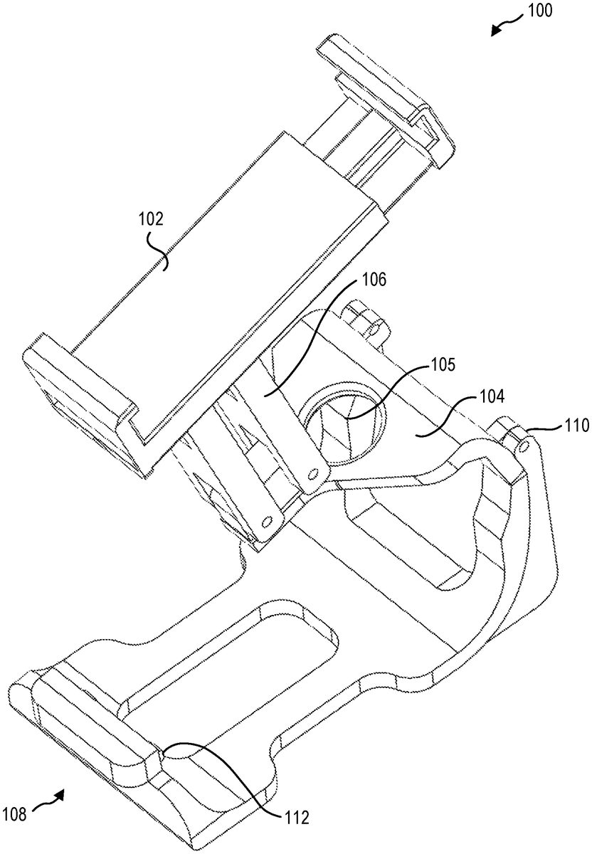
FIG. 1is a perspective view of a display mount100with a display support102and a body104. The display support102and body104are spaced apart and coupled together by an adjustable arm106positioned therebetween. In some embodiments, the arm106is a single bar that is movable relative to at least one of the display support102or the body104. In other embodiments, the arm106is movable relative to both the display support102and the body104. For example, the arm106may be hinged at a connection with the body104to allow adjustment of an angle between the arm106and the body104. In other examples, a connection between the arm106and the body104may be translatable relative to the body104. In other examples, the arm106may be connected to the display support102and/or the body104with a ball-and-socket connection, allowing movement of the arm106relative to the display support102and/or the body104with multiple degrees of freedom.
In some embodiments, the display mount100has a single arm106connecting the body104to the display support102. In other embodiments, the display mount100has two, three, four, or more arms106supporting the display support102relative to the body104.
In some embodiments, the display support102mechanically holds the electronic display. For example, the display support102may include a clip, clamp, latch, or other device that applies a compressive force to the electronic display to retain the electronic display in the display support102. In further embodiments, the display support102may include an adhesive. In yet further embodiments, the display support102may include a suction cup or other device that applies a suction to a surface of the electronic display to retain the electronic display in the display support102. In an even further embodiment, the display support102may include a magnetic connector that uses a magnetic attraction force to retain the electronic display in the display support102. Combinations of the foregoing are also within the scope of this disclosure.
In some embodiments, the body104includes a controller connection mechanism108that connects to and retains a game controller or other input device relative to the body104. The body104may include one or more apertures105through which buttons, switches, joysticks, or other input mechanisms of the game controller may be accessible.
The controller connection mechanism108may include a clip, clamp, latch, or other device that applies a compressive force to the game controller to retain the game controller in the controller connection mechanism108. In some embodiments, the controller connection mechanism108may include an adhesive. In further embodiments, the controller connection mechanism108may include a suction cup or other device that applies a suction to a surface of the game controller to retain the game controller in the controller connection mechanism108. In yet further embodiments, the controller connection mechanism108may include a magnetic connector that uses a magnetic attraction force to retain the game controller in the controller connection mechanism108. Combinations of the foregoing are also within the scope of this disclosure.
In at least one embodiment, the controller connection mechanism108is connected to the body104by a hinge110that allows the body104and controller connection mechanism108to at least partially enclose a game controller. For example, the controller connection mechanism108illustrated inFIG. 1has a hinge110that allows the body104to move relative to the controller connection mechanism108. For example, the controller connection mechanism108may apply a compressive force to the game controller to clasp the game controller. The body104may obscure at least a portion of the game controller, and the hinge110may allow temporary access to the entire face of the game controller without requiring the disconnection of the game controller from the controller connection mechanism108.
In some embodiments, the controller connection mechanism108includes a mechanical interlock with the game controller. For example, the controller connection mechanism108illustrated inFIG. 1includes a pair of protrusions112that engage with recesses in a game controller. The protrusions112or other mechanical interlocks may allow the controller connection mechanism108to securely retain the game controller and allow the body104to move relative to the controller connection mechanism108by the hinge110. In some embodiments, the body104and/or controller connection mechanism108is elastically deformable to allow the body104and/or controller connection mechanism108to bend open, receive the game controller, and elastically return to the original position and retain the game controller.
In some embodiments, the arm106is a four-bar linkage that allows movement of the display support102relative to the body104while maintaining an angle of the display support102relative to the body104.FIG. 2is a side view of the display mount100ofFIG. 1. The arm106includes a first bar114-1and a second bar114-2that are each pivotably connected to the display support102and the body104, respectively. The first bar114-1and second bar114-2are positioned parallel to one another. The first bar114-1and second bar114-2, therefore, remain parallel to one another as the display support102moves relative to the body104. The upper surface116of the body104and the display support102can, therefore, remain substantially parallel as well, in the illustrated embodiment. The display support102and body104remain at the same angle relative to one another as the display support102moves relative to the body104as will be described in relation toFIG. 4.
The body104has an upper surface116and a lower surface118, where the display support102is positioned above the upper surface116and opposite the lower surface118. The display mount center of mass (COM)119is therefore between the body104and the display support102. In some embodiments, the display mount COM119is located within the arm106. Positioning the display support above the upper surface116stacks the display above the controller, such that when a user holds the controller, the mass of the display support102and display apply less torque than having the display in plane with the body, as in a conventional mount.
FIG. 3is a side view of the display mount100with a display120positioned in the display support102and a game controller122affixed to the body104by the controller connection mechanism108. The display120is located above the upper surface116of the body104when the display120is oriented facing a user (e.g., a user holding the game controller122can see the images on the display120). The display mount100positions a display COM124of the display120above the game controller122, and the system COM127may be positioned above the upper surface116of the body104and below the display support102. In at least one example, the display mount100positions a display COM124above controller COM126of the game controller122. For example, the display COM124is above the game controller122when a vector representing the force of gravity128on the display COM124intersects the game controller122when the display120is oriented facing a user. In another example, the display COM124is above the controller COM126when the display COM124is aligned with the controller COM126with respect to the direction of gravity128when the display120is oriented facing a user.
In other embodiments, the display support102is above the body104when a vector representing the force of gravity128on the display support102intersects the body104. In another example, the display support102is above the body104when a COM of the display support102is aligned with a COM of the body102respect to the direction of gravity128. In at least one example, the display support102is above the upper surface116when a vector representing the force of gravity128on the display support102intersects the upper surface116of the body104when the upper surface116is oriented at an angle between −30° and +45° from a horizontal plane.
The display120is also located above the buttons129of the game controller122. By positioning the display COM124above the buttons129and/or above the controller COM126, the user can interact with the buttons129of the game controller122without applying a torque to the display mount100and moving the display120. For example, a MICROSOFT XBOX WIRELESS CONTROLLER has at least three directional buttons (D-pad and two joysticks), two analog triggers, two shoulder buttons, four face input buttons (X, Y, A, and B buttons), two menu and view buttons, and the system (XBOX) button. To interact with all of the buttons129for gameplay or system controls, the user grips the game controller122lightly between only the heel of the palm and the third through fifth fingers. In the example of a MICROSOFT XBOX ELITE CONTROLLER, buttons and/or switches on the rear of the game controller122(e.g., opposite the top surface130) can further limit the available dexterity to hold the controller firmly. Therefore, aligning the display COM124and controller COM126, and also aligning the display COM124and the buttons129to which the user applies forces, can stabilize the system and improve the user experience.
When a user is holding a game controller122, the user will hold the controller in front of the user, with a top surface130of the game controller122at an angle132between +45° and −30° with respect to a horizontal plane134normal to gravity128. For example, the top surface130of the game controller122illustrated inFIG. 3is oriented at a −10° angle132. In some embodiments, the arm106is movable relative to the body104, and hence the game controller122, to position the display COM124above the game controller122when the user holds the game controller122at an angle132between +45° and −30° with respect to a horizontal plane134normal to gravity128. Thus, when the upper surface130of the controller122is tilted toward the user, the angle is a positive angle132and when the upper surface130of the controller122is tilted away from the user, the angle is a negative angle132. The more closely aligned the display COM124is to the controller COM126with respect to the direction of gravity128when the user holds the game controller122at an angle132between +45° and −30° with respect to a horizontal plane134normal to gravity128, the lower the torque due to gravitational force on the total system (i.e., the display120, the display mount100, and the game controller122) can be.
For example,FIG. 4illustrates the display mount100with the four bar linkage arm106moved relative to the body104and display support102when the game controller122is oriented with the top surface130at a +45° angle132to a horizontal plane134. The arm106is moved to alter the position of the display support102relative to the body104. With the top surface130of the game controller at the +45° angle132, the display support102is moved such that the display COM124is aligned with the controller COM126.
In some embodiments, a range of motion of the arm106relative to the body104is in a range having an upper value, a lower value, or upper and lower values including any of 60°, 80°, 100°, 120°, 140°, 160°, 180°, or any values therebetween. For example, the range of motion of the arm106may be greater than 60°. In other examples, the range of motion may be less than 180°. In yet other examples, the range of motion may be between 60° and 180°. In further examples, the range of motion may be between 75° and 135°. In at least one example, the range of motion may be about 120°.
In some embodiments, with a four-bar linkage arm106with a first bar114-1and second bar114-2that are parallel and of equal length, the two surfaces to which the bars114-1,114-2are connected remain at the same orientation relative to one another. In the embodiment illustrated inFIG. 4, this means the upper surface116of the body104and a bottom surface136of the display support102remain parallel. As the top surface130of the game controller is fixed relative to the upper surface116of the body104and a display surface138of the display is fixed relative to the bottom surface of the display support102, the orientation of display surface138remains fixed relative to the angle132of the game controller122as the four bar linkage arm106moves.
In some embodiments, it may be desirable to have the orientation of a display surface change as the arm moves the display support relative to the body.FIG. 5is a side view of another embodiment of a display mount200with a four bar linkage arm260where a first bar214-1and a second bar214-2are non-parallel (for example, by adjusting a connection point240of the second bar214-2). The non-parallel first bar214-1and a second bar214-2produce a net rotation of the display support202and the body204relative to one another when the arm206moves relative to the display support202and body204. In other embodiments, the first bar214-1and second bar214-2are different lengths and may achieve similar results.
The net rotation of the display support202and the body204relative to one another provides a net rotation of the display surface236relative to a top surface230of the game controller. The orientation of the game controller and the orientation of the display surface236are selected by a user based on the ergonomics of the user's body. For example,FIG. 5illustrates a top surface230of a game controller that is parallel to a horizontal plane234.
The display surface236however, may be oriented at an angle to the horizontal plane234to tilt the display surface236toward a user for easier viewing. The body204is oriented relative to an arm axis242at a body angle244, and the display support202is oriented relative to the arm axis242at a display angle246.
As the user tilts the arm206inFIG. 6, the non-parallel linkage of the arm206compensates for a change in the height of the display support202above the body204by producing a net rotation of the display surface236to maintain the display surface236facing the user's eyes. For example, the display angle246relative to the arm axis242may decrease by a greater amount than the body angle244. The net rotation can provide a more comfortable playing experience for a user at a broader range of positions of the arm206.
Referring now toFIG. 7andFIG. 8, in some embodiments, the display support302may be adjustable to accommodate a range of display device sizes.FIG. 7is a side view of an embodiment of a display mount300with a display support302having a first portion348and a second portion350that are slidable relative to one another. The first portion348is connected to the arm306and the second portion350is movable relative to the first portion348.FIG. 7illustrates the display support302in a closed configuration andFIG. 8illustrates the display support302in a fully open configuration.
In some embodiments, the closed configuration has a closed length352in a range having an upper value, a lower value, or upper and lower values including any of 2.25 inches, 2.3″, 2.4″, 2.5″, 2.6″, 2.7″, 2.8″, 2.9″, 3.0″, or any values therebetween. For example, the closed length352may be greater than 2.25″. In other examples, the closed length352may be less than 3.0″. In yet other examples, the closed length352may be between 2.25″ and 3.0″. In further examples, the closed length352may be between 2.4″ and 2.8″. In at least one example, the closed length352may be about 2.45″.
In some embodiments, the arm306has an arm length353in a range having an upper value, a lower value, or upper and lower values including any of 1.0″, 1.5″, 2.0″, 2.5″, 3.0″, 3.5″, 4.0″, 4.5″, 5.0″, or any values therebetween. For example, the arm length353may be greater than 1.0″. In other examples, the arm length353may be less than 5.0″. In yet other examples, the arm length353may be between 1.0″ and 5.0″. In further examples, the arm length353may be between 1.5″ and 4.5′. In at least one example, the arm length353may be about 2.5″.
In other embodiments, the arm length353may be adjustable. For example, the arm306may have a telescopic linkage, allowing the user to adjust the arm length353to raise or lower the display support302relative to the body304based upon the display size, the user's arm length, and preferred body position. For example, the arm length353may be adjustable from 1.0″ to 5.0″. In other examples, the arm length353may be adjustable from 2.0″ to 3.0″.
FIG. 8shows the display support302in the fully open configuration. In some embodiments, the closed configuration has an open length354in a range having an upper value, a lower value, or upper and lower values including any of 3.0″, 3.2″, 3.4″, 3.6″, 3.8″, 4.0″, 4.5″, 5.0″, 6.0″, or any values therebetween. For example, the open length354may be greater than 3.0″. In other examples, the open length354may be less than 6.0″. In yet other examples, the open length354may be between 3.0″ and 6.0″. In further examples, the open length354may be between 3.25″ and 5.0″. In at least one example, the open length354may be about 3.5″.
FIG. 9is a side view of yet another embodiment of a display mount400according to the present disclosure. As described herein, the arm406may be rotatable relative to the body404of the display mount400. In some embodiments, the arm406is translatable relative to the body404. For example, the body404may have a body length456. The arm406is movable in the direction of the body length456and may be positioned at various locations along the body length456.
A position of the arm406may be considered to be where the arm axis442intersects the upper surface416of the body404. For example, the body end458of the arm axis442may be located at the upper surface416of the body404at a variety of locations along the body length456. In some embodiments, the body end458of the arm axis442may be at a position (e.g., movable and fixable) between 10% and 90% of the length of the body length456. In other embodiments, the body end458of the arm axis442may be at a position between 20% and 80% of the length of the body length456. In yet other embodiments, the body end458of the arm axis442may be at a position between 30% and 70% of the length of the body length456.
Referring now toFIG. 10, as described herein, the display support402may be rotatable relative to the arm406of the display mount. In some embodiments, the display support402is translatable relative to the arm406. For example, the display support402has a first portion448that is connected to the arm406. The first portion448has a support length460. The arm406may be considered connected to the first portion448of the display support402at a support end462of the arm axis442.
In some embodiments, the support end462of the arm axis442may be at a position (e.g., movable and fixable) between 10% and 90% of length of the support length460. In other embodiments, the support end462of the arm axis442may be at a position between 20% and 80% of length of the support length460. In yet other embodiments, the support end462of the arm axis442may be at a position between 30% and 70% of length of the support length460.
In some embodiments, the display mount400may support a display without a game controller positioned in the body404. A base464of the body404may be substantially flat and/or have a plurality of feet to rest on a flat surface, such as a table or desk. The display mount400may support a display on the table or desk while orienting the display toward the user. The user can then interact with the display through a game controller. When the user desires to move locations and take the display and game controller to a new location, the user can attach the game controller to the body404and use the display mount400to connect the game controller to the display device.
In some embodiments, a base464of the body404may not provide a sufficiently stable support for the display device. In a particular example, a display support402that is translatable relative to the body404, either by being translatable relative to the arm406, the arm406being translatable relative to the body404, or both, the display COM may move forward relative to the body404and cause the display mount400to become unstable on the surface when used as a stand.
The body404may include one or more features to extend the464to increase stability when used as a stand. For example,FIG. 11is a side view of another embodiment of a display mount500that has a deployable extension568that extends from the body504. In some embodiments, the movement of the display support502and/or arm506relative to the body504can move a display COM524near or beyond an edge of the base564. The extension568may extend by folding out from the body504, sliding out from the body504, being removably connected to the body504(e.g., being snapped onto the body504), or by other mechanisms. The extension568may increase the footprint of the body504to stabilize the display mount500.
The extension568has an extension length570that is related to a base length566. In some embodiments, the extension length570may be a percentage of the base length566in a range having an upper value, a lower value, or upper and lower values including any of 20%, 30%, 40%, 50%, 60%, 70%, 80%, 90%, 100%, or any values therebetween. For example, the extension length570may be greater than 20% of the base length566. In other examples, the extension length570may be less than 100% of the base length566. In yet other examples, the extension length570may be between 20% and 100% of the base length566. In further examples, the extension length570may be between 33% and 66%. In at least one example, the extension length570may be about 50% of the base length566. While the embodiment illustrated inFIG. 11show the extension568positioned at a front edge of the base564, in other embodiments, an extension568may be positioned at the front edge of the base564, a rear edge of the base564, or both.
In at least some embodiments according to the present disclosure, a display mount connects a game controller to a display device to allow a user to interact with a game or other application on the display device using the game controller. The display mount positions the display above the game controller to align a COM of the display device above the game controller, thereby improving the user experience by reducing fatigue and improving control of the game controller.
The articles “a,” “an,” and “the” are intended to mean that there are one or more of the elements in the preceding descriptions. The terms “comprising,” “including,” and “having” are intended to be inclusive and mean that there may be additional elements other than the listed elements. Additionally, it should be understood that references to “one embodiment” or “an embodiment” of the present disclosure are not intended to be interpreted as excluding the existence of additional embodiments that also incorporate the recited features. For example, any element described in relation to an embodiment herein may be combinable with any element of any other embodiment described herein. Numbers, percentages, ratios, or other values stated herein are intended to include that value, and also other values that are “about” or “approximately” the stated value, as would be appreciated by one of ordinary skill in the art encompassed by embodiments of the present disclosure. A stated value should therefore be interpreted broadly enough to encompass values that are at least close enough to the stated value to perform a desired function or achieve a desired result. The stated values include at least the variation to be expected in a suitable manufacturing or production process, and may include values that are within 5%, within 1%, within 0.1%, or within 0.01% of a stated value.
A person having ordinary skill in the art should realize in view of the present disclosure that equivalent constructions do not depart from the spirit and scope of the present disclosure, and that various changes, substitutions, and alterations may be made to embodiments disclosed herein without departing from the spirit and scope of the present disclosure. Equivalent constructions, including functional “means-plus-function” clauses are intended to cover the structures described herein as performing the recited function, including both structural equivalents that operate in the same manner, and equivalent structures that provide the same function. It is the express intention of the applicant not to invoke means-plus-function or other functional claiming for any claim except for those in which the words ‘means for’ appear together with an associated function. Each addition, deletion, and modification to the embodiments that falls within the meaning and scope of the claims is to be embraced by the claims.
It should be understood that any directions or reference frames in the preceding description are merely relative directions or movements. For example, any references to “front” and “back” or “top” and “bottom” or “left” and “right” are merely descriptive of the relative position or movement of the related elements.
The present disclosure may be embodied in other specific forms without departing from its spirit or characteristics. The described embodiments are to be considered as illustrative and not restrictive. The scope of the disclosure is, therefore, indicated by the appended claims rather than by the foregoing description. Changes that come within the meaning and range of equivalency of the claims are to be embraced within their scope.
Claims
- A display mount for connecting electronic devices, the display mount comprising: a body having a controller connection mechanism, the body having a lower surface and an opposing upper surface, the lower surface of the body configured to abut an upper surface of a controller;a display support;and a movable arm connected to the body on the upper surface and to the display support, the arm positioned above the upper surface to hold the display support above the body and opposite the lower surface.
- The display mount of claim 1 , the arm having a range of motion of at least 60° relative to the body.
- The display mount of claim 1 , the controller connection mechanism being elastically deformable to apply a compressive force to a game controller.
- The display mount of claim 1 , the controller connection mechanism including at least one interlocking feature configured to interlock with a complementary feature of a game controller.
- The display mount of claim 1 , the display support being positioned above the body when the upper surface is oriented at an angle between −30° and 45° with a horizontal plane.
- The display mount of claim 1 , the display support including a first portion and a second portion slidable relative to the first portion.
- The display mount of claim 1 , the arm having a length in a range of 1.0 inch to 5.0 inches.
- The display mount of claim 1 , the arm being adjustable in length.
- The display mount of claim 1 , the body having a body length from a front edge to a rear edge, the arm being connected to the upper surface at a position between 10% and 90% along the body length.
- The display mount of claim 1 , a display mount center of mass (COM) of the display mount being located between the upper surface of the body and the display support.
- The display mount of claim 10 , the display mount COM being located in the arm.
- The display mount of claim 1 , the display support being translatable relative to the arm.
- The display mount of claim 1 , the body being translatable relative to the arm.
- The display mount of claim 1 , the arm including a four bar linkage.
- The display mount of claim 14 , the arm including a first bar and a second bar, where the first bar and second bar are not parallel or have different lengths.
- A system for holding and controlling an electronic device, the system comprising: a display device;a game controller;and a display mount connected to the display device and the game controller, the display mount including: a body having a controller connection mechanism connected to the game controller, the body having a lower surface and an upper surface, a display support connected to the display device, and a movable arm connected to the body and the display support, the arm positioned above the upper surface to hold the display support above the body and opposite the lower surface, wherein the moveable arm is connected to the display support and the controller connection mechanism.
- The system of claim 16 , the display device being a smartphone.
- The system of claim 16 , the movable arm connected to the body and the display support to position the display device and the game controller relative to the display mount such that a system COM is between the upper surface of the body and the display support, the system COM being located in the arm.
- The system of claim 16 , the game controller having a top surface and a display COM of the display device being above the top surface with respect to a direction of gravity when the top surface is between −30° and 45° with a horizontal plane.
- A display mount for connecting electronic devices, the display mount comprising: a body having a controller connection mechanism, the body having a lower surface and an upper surface and the controller connection mechanism being elastically deformable to apply a first compressive force to a game controller;a display support including a first portion and a second portion that is slidable relative to the first portion to apply a second compressive force to a display device;and a moveable arm connected to the body and the display support, the moveable arm positioned above the upper surface to hold the display support above the body and opposite the lower surface, wherein the moveable arm is connected to the body such that the arm is oriented to extend from a controller when the controller is connected to the body.
Disclaimer: Data collected from the USPTO and may be malformed, incomplete, and/or otherwise inaccurate.