U.S. Pat. No. 11,179,628
REPLACEABLE CONTROL MODULE AND GAME CONTROLLER INCLUDING THE SAME
AssigneeCheng Uei Precision Industry Co., Ltd.
Issue DateMarch 2, 2020
Illustrative Figure
Abstract
A replaceable control module includes a base and an operation module. The base includes an upper cover, at least one buckling portion, at least one first elastic element, a driving rotation handle, at least one second elastic element and a cam assembly. A top surface of the upper cover has an assembling groove and a perforation. The at least one buckling portion is disposed to the upper cover. The at least one first elastic element is connected between the upper cover and the at least one buckling portion. The driving rotation handle is disposed in the upper cover. The at least one second elastic element is connected between the upper cover and the driving rotation handle. The cam assembly is disposed between the at least one buckling portion and the driving rotation handle. The operation module is assembled in the assembling groove.
Description
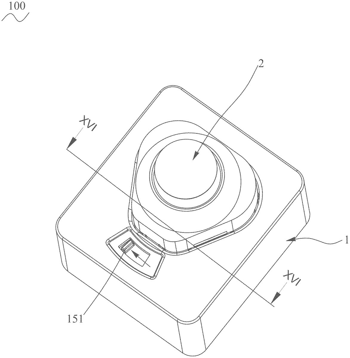
DETAILED DESCRIPTION OF THE PREFERRED EMBODIMENT With reference toFIG. 1toFIG. 4, a replaceable control module100in accordance with a first preferred embodiment of the present invention is shown. The replaceable control module100is adapted for being applied in a game controller200. The game controller200includes a shell300, and the replaceable control module100mounted to the shell300of the game controller200. The replaceable control module100includes a base1and an operation module2. The operation module2is placed in the base1from top to bottom. Referring toFIG. 5toFIG. 7, the base1includes an upper cover11, at least one torsion spring12, at least one buckling portion13, at least one tension spring14, a driving rotation handle15, a circuit board16, a plurality of screws17and a lower cover18. The at least one buckling portion13is disposed to the upper cover11. The base1includes a plurality of buckling portions13and a plurality of tension springs14. The base1includes at least one first elastic element31and at least one second elastic element32. The at least one first elastic element31is the at least one tension spring14. The at least one second elastic element32is the at least one torsion spring12. The at least one torsion spring12is disposed to a top surface of the driving rotation handle15. The at least one torsion spring12is used for rebounding a position of the driving rotation handle15. The at least one buckling portion13is located to the top surface of the driving rotation handle15. The plurality of the buckling portions13are located to the top surface of the driving rotation handle15. The driving rotation handle15is disposed in the upper cover11. The at least one buckling portion13is used for fastening a corresponding mechanism of the operation module2to realize fixing and locating the base1with the operation module2. The plurality of the buckling portions13are used for fastening corresponding mechanisms of the operation module2to realize locating and fixing the base1with the operation module2. The at least ...
DETAILED DESCRIPTION OF THE PREFERRED EMBODIMENT
With reference toFIG. 1toFIG. 4, a replaceable control module100in accordance with a first preferred embodiment of the present invention is shown. The replaceable control module100is adapted for being applied in a game controller200. The game controller200includes a shell300, and the replaceable control module100mounted to the shell300of the game controller200. The replaceable control module100includes a base1and an operation module2. The operation module2is placed in the base1from top to bottom.
Referring toFIG. 5toFIG. 7, the base1includes an upper cover11, at least one torsion spring12, at least one buckling portion13, at least one tension spring14, a driving rotation handle15, a circuit board16, a plurality of screws17and a lower cover18. The at least one buckling portion13is disposed to the upper cover11. The base1includes a plurality of buckling portions13and a plurality of tension springs14. The base1includes at least one first elastic element31and at least one second elastic element32. The at least one first elastic element31is the at least one tension spring14. The at least one second elastic element32is the at least one torsion spring12. The at least one torsion spring12is disposed to a top surface of the driving rotation handle15.
The at least one torsion spring12is used for rebounding a position of the driving rotation handle15. The at least one buckling portion13is located to the top surface of the driving rotation handle15. The plurality of the buckling portions13are located to the top surface of the driving rotation handle15. The driving rotation handle15is disposed in the upper cover11. The at least one buckling portion13is used for fastening a corresponding mechanism of the operation module2to realize fixing and locating the base1with the operation module2. The plurality of the buckling portions13are used for fastening corresponding mechanisms of the operation module2to realize locating and fixing the base1with the operation module2. The at least one first elastic element31is disposed and connected between the upper cover11and the at least one buckling portion13.
The at least one torsion spring12is disposed to an inner side of the at least one first elastic element31. The at least one torsion spring12is disposed to inner sides of the plurality of the buckling portions13. Each tension spring14is disposed under one buckling portion13, and one end of each tension spring14hooks a corresponding mechanism of the one buckling portion13. The other end of each tension spring14hooks a corresponding mechanism of the upper cover11to realize that each buckling portion13is pushed outward by one tension spring14to move a distance to return to an original position. The circuit board16is disposed to a bottom surface of the driving rotation handle15. The circuit board16is used for making a circuit breakover at the time of the circuit board16contacting with the corresponding mechanism of the operation module2. The lower cover18is disposed to a bottom surface of the circuit board16. The plurality of the screws17are used for locking the circuit board16and the lower cover18under the upper cover11.
Referring toFIG. 5toFIG. 17, a top of the upper cover11has an assembling groove111, at least one buckling groove112, a plurality of openings113and a perforation114. The perforation114is arched outward to show an arc shape. An inside of the upper cover11has an accommodating groove101. The upper cover11opens the accommodating groove101penetrating through a bottom surface of the upper cover11. A middle of a top surface of the upper cover11is recessed downward to form the assembling groove111. The assembling groove111has a bottom wall116, and a peripheral wall117connected with a periphery of the bottom wall116. The peripheral wall117has the at least one buckling groove112. Preferably, the peripheral wall117has a plurality of the buckling grooves112. The assembling groove111is surrounded between an inner surface of the peripheral wall117and a top surface of the bottom wall116. The bottom wall116is connected with a bottom of the peripheral wall117. The plurality of the buckling grooves112penetrate through the peripheral wall117of the assembling groove111. The plurality of the buckling grooves112are communicated with the accommodating groove101. The plurality of the openings113penetrate through the bottom wall116of the assembling groove111. A front of the upper cover11opens the perforation114penetrating through a top wall of the accommodating groove101and communicated with the accommodating groove101.
The inside of the upper cover11further has a plurality of abutting portions102, at least one first location piece103, a fixing hole108, a location pillar110, a restricting groove115and a third location piece118. Preferably, the inside of the upper cover11has a plurality of the location pillars110. The inside of the upper cover11has a plurality of the first location pieces103. The assembling groove111is used for receiving the operation module2. The plurality of the buckling grooves112and the plurality of the openings113are located in the assembling groove111. The perforation114is disposed to one side of the assembling groove111. The plurality of the buckling grooves112penetrate through the peripheral wall117of the assembling groove111. The plurality of the buckling grooves112are communicated between the assembling groove111and the accommodating groove101.
A middle of a bottom surface of the bottom wall116of the assembling groove111extends downward to form the third location piece118. The third location piece118surrounds a receiving groove119inside the third location piece118. The plurality of the openings113are communicated with the receiving groove119. The receiving groove119is used for receiving a corresponding mechanism of the circuit board16. The third location piece118surrounds a loop to show an annular shape. Several portions of a bottom of the third location piece118extend outward to form the plurality of the abutting portions102. The plurality of the abutting portions102are used for abutting against the driving rotation handle15to make the driving rotation handle15keep in a preset position.
Several portions of the bottom surface of the bottom wall116of the assembling groove111protrude downward to form the plurality of the first location pieces103. Each first location piece103is arched outward to show a bow shape. The plurality of the first location pieces103are disposed around an outer periphery of the third location piece118. A space201is formed between the third location piece118and the plurality of the first location pieces103. The at least one torsion spring12is disposed in the space201between the third location piece118and the plurality of the first location pieces103. A middle portion of the at least one torsion spring12is disposed in the space201and disposed between the third location piece118and the at least one first location piece103.
The upper cover11has a location block104. Preferably, several portions of the bottom surface of the bottom wall116of the assembling groove111protrude downward and slantwise extend sideward to form a plurality of L-shaped location blocks104seen from a bottom view. Each location block104is located to an outer side of one first location piece103. The other end of each tension spring14hooks the location block104. The upper cover11has a plurality of ribs105protruded downward from the bottom surface of the bottom wall116of the assembling groove111. Each location block104is located between and spaced from two parallel ribs105. The plurality of the ribs105are used to be buckled with corresponding mechanisms of the plurality of the buckling portions13to realize locating and fixing the upper cover11with the plurality of the buckling portions13.
A bottom surface of each rib105protrudes downward to form a circular column109. The circular columns109of the plurality of the ribs105are disposed in the corresponding mechanisms of the plurality of the buckling portions13to limit a moving distance of the plurality of the buckling portions13. The bottom surface of the bottom wall116of the assembling groove111has a plurality of concave surfaces106. Each concave surface106is disposed between the two parallel ribs105. The plurality of the concave surfaces106of the upper cover11are located adjacent to and spaced from outer sides of the plurality of the location blocks104. The plurality of the concave surfaces106are used for fastening the corresponding mechanisms of the plurality of the buckling portions13to realize locating and fixing the upper cover11with the plurality of the buckling portions13. Several portions of the peripheral wall117extend outward to form a plurality of second location pieces107. Each two second location pieces107are corresponding to the two parallel ribs105. Each buckling groove112is located between two second location pieces107.
The plurality of the second location pieces107are used to limit a position of each buckling portion13so as to realize locating and fixing the upper cover11with the plurality of the buckling portions13. A bottom surface of the bottom wall116of the assembling groove111of the upper cover11has the fixing hole108. One end of the at least one torsion spring12is disposed in the fixing hole108. The bottom surface of the bottom wall116of the assembling groove111of the upper cover11has a plurality of location pillars110protruded downward. The circuit board16and the lower cover18are fastened to positions of the plurality of the location pillars110by the plurality of the screws17. The bottom surface of the bottom wall116of the assembling groove111of the upper cover11has a restricting groove115. The restricting groove115is used for locking a corresponding mechanism of the driving rotation handle15to make the driving rotation handle15incapable of rotating. The at least one second elastic element32is disposed and connected between the upper cover11and the driving rotation handle15.
In the preferred embodiment, a quantity of the plurality of the first location pieces103is corresponding to a quantity of the plurality of the location block104. The quantity of the plurality of the first location pieces103is corresponding to a quantity of the plurality of the concave surface106. The quantity of the plurality of the first location pieces103is corresponding to a quantity of the plurality of the buckling portions13. A quantity of the plurality of the ribs105is corresponding to a quantity of the plurality of the second location pieces107. The third location piece118is shown as a circular ring shape. The plurality of the first location pieces103are averagely distributed around an outer periphery of the third location piece118. Each first location piece103is disposed along a radial direction of the third location piece118. The plurality of the location blocks104are averagely dispersed around outer sides of the plurality of the first location pieces103, and each location block104is corresponding to one first location piece103. Each location block104is disposed to the outer side of the one first location piece103. Each location block104is disposed along the radial direction of the third location piece118.
The plurality of the concave surfaces106are averagely dispersed around outer sides of the plurality of the location blocks104, and each concave surface106is corresponding to one location block104. Each concave surface106is disposed adjacent to and spaced from the outer side of the one location block104. Each concave surface106is disposed along the radial direction of the third location piece118. Each two ribs105are disposed as a pair. The plurality of the ribs105are disposed as a plurality of pairs of the ribs105. The plurality of the pairs of the ribs105are averagely dispersed around the third location piece118and the plurality of the first location pieces103. Each pair of the ribs105are disposed along the radial direction of the third location piece118. Each location block104is located between one pair of the ribs105. Each concave surface106is disposed between the one pair of the ribs105. The concave surface106disposed between the one pair of the ribs105is located adjacent to and spaced from the outer side of the location block104located between the one pair of the ribs105.
Each two second location pieces107are disposed as a pair, so the plurality of the second location pieces107are disposed as a plurality of pairs. The plurality pairs of the second location pieces107are dispersed along the radial directions of the third location piece118. Each pair of the second location pieces107is disposed to an outer side of one concave surface106. A portion between each pair of the second location pieces107has one buckling groove112. In the preferred embodiment, the replaceable control module100includes three first location pieces103, three location blocks104, three pairs of the ribs105, namely six ribs105, three concave surfaces106, three pairs of the second location pieces107, namely six second location pieces107, three buckling grooves112and three buckling portions13.
Referring toFIG. 9toFIG. 17, each buckling portion13has at least two limiting portions130, a locking hook131, a driving cylinder132disposed to the buckling portion13, a bottom board134, a lateral board133connected with the bottom board134, a plurality of limiting holes135, a protruding block136, a fastening groove137, a convex surface138and a plurality of extending portions139. So the at least one buckling portion13has the driving cylinder132disposed to the at least one buckling portion13. In the preferred embodiment, each buckling portion13has two limiting portions130. Two sides of a top surface of the bottom board134are concaved downward to form the two limiting portions130. Each limiting portion130is used for buckling with one rib105to realize locating and fixing the upper cover11with the plurality of the buckling portions13. A free end of the lateral board133protrudes inward to form the locking hook131. The locking hook131is hooked in and penetrates through the at least one buckling groove112, and the locking hook131projects into the assembling groove111. The locking hook131is locked in the buckling groove112. The locking hook131is locked to the corresponding mechanism of the operation module2to realize locating and fixing the base1with the operation module2. One side of a bottom surface of the bottom board134protrudes downward to form the driving cylinder132. So the driving cylinder132is disposed to the one side of the bottom surface of the bottom board134. The driving cylinder132is disposed to the corresponding mechanism of the driving rotation handle15. Each limiting portion130has a limiting hole135. The limiting hole135is a through-hole. The operation module2is assembled in the assembling groove111of the base1, the circular column109of each rib105is disposed in the limiting hole135of one limiting portion130.
When the operation module2is placed in the base1, the circular column109of each rib105is located at one end of the one limiting hole135. When the operation module2is changed, the circular column109of each rib105is movable in the one limiting hole135. An outer portion of the bottom surface of the bottom board134extends downward to form the protruding block136. A portion between the lateral board133and the protruding block136is recessed inward to form a fastening groove137. The one end of each tension spring14hooks a position of the fastening groove137to realize that the plurality of the buckling portions13is moved outward by the tension spring14and along a distance to return to original positions. The convex surface138is located among the at least two limiting portions130. In the preferred embodiment, the convex surface138is located between the two limiting portions130.
The convex surfaces138of the three buckling portions13are used for abutting against the three concave surfaces106of the upper cover11to realize locating and fixing the plurality of the buckling portions13with the upper cover11. At least two portions of the bottom surface of the bottom board134extend downward to form at least two extending portions139. In the preferred embodiment, two sides of the bottom surface of the bottom board134extend downward to form two extending portions139. The two extending portions139are located to a left side and a right side of the convex surface138. Two portions of the bottom surface of the bottom board134extend downward to form two extending portions139. A gap301is formed among the two extending portions139and the convex surface138of each limiting portion130. The gap301of each limiting portion130is used for placing the one tension spring14therein. The two extending portions139are located to two sides of the one tension spring14.
Referring toFIG. 11,FIG. 13andFIG. 14, the driving rotation handle15has an operation pole151, a convex clasp152, at least one cam groove153disposed in the driving rotation handle15, a circular pad154, a plurality of stopping portions155, a crack156, a limiting groove157, a fastening portion158and a pivoting hole159. A bottom of the operation pole151extends sideward to form a sliding portion150. The sliding portion150is shown as a sector shape. The sliding portion150opens the limiting groove157. A middle of the operation pole151is arched outward to show the arc shape. A middle of the limiting groove157is slightly curved outward. The operation pole151is substantially matched with the perforation114. Preferably, a plurality of the cam grooves153are disposed in the driving rotation handle15. Two opposite ends of the fastening portion158are connected with the circular pad154and the operation pole151, respectively. The operation pole151projects beyond a top surface of the fastening portion158. A middle of a top surface of the operation pole151protrudes upward to form an operation portion501. The operation pole151is disposed to and exposed to the perforation114. The operation portion501of the operation pole151penetrates through the perforation114and is exposed out of the upper cover11. The operation pole151is used for operating and changing the operation module2. One side of the fastening portion158has the convex clasp152protruded outward. The convex clasp152is restricted in or breaks away from the restricting groove115of the upper cover11to make the driving rotation handle15stop rotating or rotate. The convex clasp152is used for being restricted in the restricting groove115of the upper cover11to block the driving rotation handle15to make the driving rotation handle15stop rotating.
In the preferred embodiment, the convex clasp152is restricted in the restricting groove115of the upper cover11. The circular pad154has the plurality of the cam grooves153. The at least one cam groove153is disposed to the circular pad154. The driving cylinders132of the at least two limiting portions130are disposed in the plurality of the cam grooves153, respectively. The at least one cam groove153includes a line groove1531and an arc-shaped sliding groove1532communicated with each other. Each cam groove153includes the line groove1531and the arc-shaped sliding groove1532communicated with each other. When the operation module2is placed in the base1, the plurality of the buckling portions13will move outward in the distance, and the driving cylinders132of the plurality of the buckling portions13slide in the line groove1531, and the driving cylinders132of the plurality of the buckling portions13move from one end of the line groove1531to the other end of the line groove1531to generate the distance of the driving cylinders132of the plurality of the buckling portions13moving. When the driving cylinders132of the plurality of the buckling portions13are fastened, the driving cylinders132of the plurality of the buckling portions13will return to original positions.
When the operation module2is changed, the driving rotation handle15will rotate, at the moment, the driving cylinder132of the at least one buckling portion13moves in the arc-shaped sliding groove1532of the at least one cam groove153, preferably, the driving cylinders132of the plurality of the buckling portions13will move in the arc-shaped sliding grooves1532of the plurality of the cam grooves153, when the operation module2is completed being changed, the driving cylinders132of the plurality of the buckling portions13will return to the original positions. Several portions of an outer periphery of a top surface of the circular pad154protrude upward to form the plurality of the stopping portions155. The plurality of the buckling portions13are disposed between the two stopping portions155. One side of each buckling portion13is disposed adjacent to one side of one stopping portion155. When the operation portion501of the operation pole151is moved towards a direction where an arrow points, the driving rotation handle15rotates, the plurality of the buckling portions13will move towards the other stopping portion155which is far away from the plurality of the buckling portions13.
The one end of the at least one torsion spring12is located in the fixing hole108. The crack156is disposed between the two stopping portions155for fastening the other end of the at least one torsion spring12. The other end of the at least one torsion spring12is disposed in the crack156. The torsion spring12is disposed between the crack156and the fixing hole108. The limiting groove157is a through-hole. The limiting groove157is formed in the fastening portion158. The location pillar110passes through and is movably disposed in the limiting groove157. When the operation module2is to be changed, the location pillar110abuts against one side wall of the limiting groove157. When the operation module2is placed in the base1, the location pillar110abuts against the other side wall of the limiting groove157. The pivoting hole159is formed in a center portion of the circular pad154. The plurality of the abutting portions102are buckled to an edge of the pivoting hole159.
Referring toFIG. 6andFIG. 7, the circuit board16has a plurality of first location holes161, a plurality of spring pins162and a pivoting shaft163. The pivoting shaft163is disposed to a top surface of the circuit board16. A top of each spring pin162extends upward and projects beyond a top surface of the pivoting shaft163. A bottom of each spring pin162is connected with the circuit board16. The pivoting shaft163penetrates through the pivoting hole159and is received in the accommodating groove101. The plurality of the spring pins162penetrate through the plurality of the openings113. Tops of the plurality of the spring pins162are exposed in the assembling groove111. When the plurality of the spring pins162contact with the corresponding mechanism of the operation module2to make a circuit breakover, the lower cover18has a plurality of second location holes181. In the preferred embodiment, positions of the plurality of first location holes161are corresponding to positions of the plurality of the second location holes181. The plurality of the screws17are locked in the plurality of the first location holes161and the plurality of the second location holes181, respectively.
Referring toFIG. 4toFIG. 7, one side surface of the operation module2has at least one snapping groove21. The operation module2has a plurality of snapping grooves21and a bare copper area22. Several portions of a peripheral surface of the operation module2are recessed inward to form the plurality of the snapping grooves21. The at least one snapping groove21is corresponding to the locking hook131of the at least one buckling portion13. Each snapping groove21is corresponding to the locking hook131of one buckling portion13to realize locating and fixing the operation module2with the base1. A bottom surface of the operation module2has the bare copper area22. When the bare copper area22is used for contacting with the plurality of the spring pins162of the circuit board16to make the circuit breakover, a shape of the operation module2is matched with the assembling groove111to make the operation module2received in the assembling groove111. In practice, the operation module2is a rocker cap or a direction key cap. The operation module2is disposed in the assembling groove111.
Referring toFIG. 2toFIG. 14, in use, the operation module2is placed in the assembling groove111from top to bottom, an outer surface of the operation module2pushes an inclined surface of the locking hook131of each buckling portion13. The at least one buckling portion13and the at least one tension spring14are pushed outward along the distance, the driving cylinders132of the plurality of the buckling portions13move the distance towards an outer side of the line groove1531. When the locking hook131of the at least one buckling portion13is corresponding to the at least one snapping groove21, the locking hook131of the at least one buckling portion13is locked in the at least one snapping groove21to realize locating and fixing the operation module2with the base1. When the locking hook131of each buckling portion13is corresponding to a position of one snapping groove21, the locking hook131of each buckling portion13is locked in the one snapping groove21to realize locating and fixing the operation module2with the base1. The at least one tension spring14brings along each buckling portion13to return to the original position, at the moment, the driving cylinder132of each buckling portion13is returned to the original position. At the same time, the bare copper area22contact with the plurality of the spring pins162of the circuit board16to make the circuit breakover. The convex clasp152of the driving rotation handle15is buckled to the restricting groove115of the bottom surface of the upper cover11to make the driving rotation handle15without rotating. In practice, the plurality of the spring pins162of the circuit board16are capable of being replaced by connection terminals.
Referring toFIG. 15toFIG. 18, when the operation module2need be changed, a finger stirred the operation portion501of the operation pole151towards the direction where the arrow pointed, the driving rotation handle15rotates, each convex clasp152of the driving rotation handle15breaks away from the restricting groove115of the upper cover11. The driving cylinders132move in the arc-shaped sliding grooves1532of the plurality of the cam grooves153. The at least one buckling portion13and the at least one tension spring14move outward along the distance and recede from the plurality of the snapping grooves21. Simultaneously, the plurality of the spring pins162in the assembling groove111push the operation module2to move upward to make the operation module2break away from the upper cover11and bounce up immediately, so the operation module2is capable of being taken out from the assembling groove111.
When a force on the finger is relieved, the driving rotation handle15is automatically rebounded to an initial position on account of a function of the at least one torsion spring12. The at least one tension spring14drives each buckling portion13to return to the original position, at the moment, the driving cylinder132of each buckling portion13is returned to the original position. The driving cylinders132of the plurality of the buckling portions13and the plurality of the cam grooves153form a cam assembly40to make the driving rotation handle15bring along each buckling portion13to move outward at the time of the driving rotation handle15rotating. In practice, the at least one tension spring14and the at least one torsion spring12are capable of being replaced by the at least one first elastic element31which has the same function as function of the at least one tension spring14and the at least one second elastic element32which has the same function as function of the at least one torsion spring12, respectively. The cam assembly40is disposed between the at least one buckling portion13and the driving rotation handle15. Correspondingly, the cam assembly40includes the driving cylinder132disposed to the at least one buckling portion13, and the at least one cam groove153disposed in the driving rotation handle15. The driving cylinder132of the at least one buckling portion13is movably disposed in the at least one cam groove153.
When the operation portion501of the operation pole151rotates, the driving rotation handle15drives the at least one buckling portion13to move outward by virtue of the cam assembly40so as to make the locking hook131of the at least one buckling portion13break away from the at least one snapping groove21, the location pillar110abuts against the one side wall of the limiting groove157, when the operation portion501of the operation pole151is returned to the initial position, the at least one first elastic element31and the at least one second elastic element32drive the driving rotation handle15and the at least one buckling portion13to return to the initial position and the original position, respectively, the location pillar110abuts against the other side wall of the limiting groove157. Specifically, when the operation pole151rotates, the driving rotation handle15drives each buckling portion13to move outward by virtue of the cam assembly40so as to make the locking hook131of each buckling portion13break away from the snapping groove21. When the operation pole151of the driving rotation handle15is returned to the initial position, the at least one first elastic element31and the at least one second elastic element32drive the driving rotation handle15and each buckling portion13to return to the initial position and the original position, respectively.
As described above, when the operation module2need be changed, the finger stirred the operation portion501of the operation pole151, the driving rotation handle15rotates, each convex clasp152of the driving rotation handle15breaks away from the restricting groove115of the upper cover11, the driving cylinders132of the plurality of the buckling portions13are movably disposed in the arc-shaped sliding grooves1532of the plurality of the cam grooves153, the at least one buckling portion13and the at least one tension spring14move outward along the distance and recede from the plurality of the snapping grooves21, simultaneously, the plurality of the spring pins162in the assembling groove111push the operation module2to move upward to make the operation module2break away and bounce up immediately, so the operation module2is capable of being taken out from the assembling groove111, when the force on the finger is relieved, the driving rotation handle15is automatically rebounded to the initial position on account of the function of the at least one torsion spring12, and the at least one tension spring14drives each buckling portion13to return to the original position, at the moment, the driving cylinders132of the plurality of the buckling portions13are returned to the original positions, the operation module2is placed in the assembling groove111from top to bottom, the operation module2pushes the inclined surface of the locking hook131, the at least one buckling portion13and the at least one tension spring14are pushed outward along the distance, the driving cylinders132move the distance towards the outside of the line groove1531, when the locking hook131is corresponding to the position of each snapping groove21, the locking hook131is locked in the snapping groove21to realize locating and fixing the operation module2with the base1, the tension spring14brings along each buckling portion13to return to the original position, at the moment, the driving cylinders132of the plurality of the buckling portions13are returned to the original positions, at the same time, the bare copper area22contacts with the plurality of the spring pins162of the circuit board16to make the circuit breakover, the convex clasp152of the driving rotation handle15is buckled to the restricting groove115of the bottom surface of the upper cover11to make the driving rotation handle15without rotating, so the replaceable control module100is capable of being applied in a current game controller.
Claims
- A replaceable control module adapted for being applied in a game controller, comprising: a base, including an upper cover, a top surface of the upper cover having an assembling groove and a perforation, the assembling groove having a peripheral wall, the peripheral wall having at least one buckling groove, at least one buckling portion disposed to the upper cover, each buckling portion having a locking hook, the locking hook penetrating through the at least one buckling groove and projecting into the assembling groove, at least one first elastic element connected between the upper cover and the at least one buckling portion, a driving rotation handle disposed in the upper cover, the driving rotation handle having an operation pole, the operation pole being disposed to and exposed to the perforation, at least one second elastic element connected between the upper cover and the driving rotation handle, a cam assembly disposed between the at least one buckling portion and the driving rotation handle;and an operation module assembled in the assembling groove, one side surface of the operation module having at least one snapping groove, the locking hook of the at least one buckling portion being locked in the at least one snapping groove, wherein when the operation pole rotates, the driving rotation handle drives the at least one buckling portion to move outward by virtue of the cam assembly so as to make the locking hook of the at least one buckling portion break away from the at least one snapping groove, when the operation pole is returned to an initial position, the at least one first elastic element and the at least one second elastic element drive the driving rotation handle and the at least one buckling portion to return to the initial position and an original position, respectively.
- The replaceable control module as claimed in claim 1 , wherein the cam assembly includes a driving cylinder disposed to the at least one buckling portion, and at least one cam groove disposed in the driving rotation handle, the driving cylinder of the at least one buckling portion is movably disposed in the at least one cam groove.
- The replaceable control module as claimed in claim 2 , wherein each buckling portion has a bottom board, the driving cylinder is disposed to one side of a bottom surface of the bottom board, the driving rotation handle has a circular pad, the at least one cam groove is disposed to the circular pad, each cam groove includes a line groove and an arc-shaped sliding groove communicated with each other, the driving cylinder of the at least one buckling portion moves in the arc-shaped sliding groove of the at least one cam groove.
- The replaceable control module as claimed in claim 1 , wherein the at least one first elastic element is at least one tension spring, each buckling portion has a fastening groove, the upper cover has a location block, one end of each tension spring hooks the fastening groove, the other end of each tension spring hooks the location block.
- The replaceable control module as claimed in claim 4 , wherein each buckling portion has a bottom board, two sides of a bottom surface of a bottom board extend downward to form two extending portions, the two extending portions are located to two sides of the tension spring.
- The replaceable control module as claimed in claim 5 , wherein each buckling portion has a lateral board connected with the bottom board, the bottom board extends downward to form a protruding block, a portion between the lateral board and the protruding block is recessed inward to form the fastening groove.
- The replaceable control module as claimed in claim 1 , wherein the at least one second elastic element is at least one torsion spring, the upper cover has a fixing hole, the driving rotation handle has a crack, one end of the at least one torsion spring is disposed in the fixing hole, the other end of the at least one torsion spring is disposed in the crack.
- The replaceable control module as claimed in claim 7 , wherein the upper cover has at least one first location piece and a third location piece, a middle portion of the at least one torsion spring is disposed between the third location piece and the at least one first location piece.
- The replaceable control module as claimed in claim 1 , wherein the assembling groove has a bottom wall, and a peripheral wall connected with a periphery of the bottom wall, an inside of the upper cover has a location pillar, the driving rotation handle has a limiting groove, the location pillar is movably disposed in the limiting groove.
- The replaceable control module as claimed in claim 9 , wherein a bottom surface of the bottom wall of the assembling groove of the upper cover has a restricting groove, the driving rotation handle has a convex clasp, the convex clasp is restricted in or breaks away from the restricting groove to make the driving rotation handle stop rotating or rotate.
- The replaceable control module as claimed in claim 1 , wherein the perforation is arched outward to show an arc shape, a middle of the operation pole is arched outward to show the arc shape, the operation pole is substantially matched with the perforation.
- A replaceable control module mounted to a game controller, comprising: an upper cover, a top surface of the upper cover being recessed downward to form an assembling groove, a front of the upper cover opening a perforation penetrating through a top wall of an accommodating groove and communicated with the accommodating groove, the assembling groove having a peripheral wall, the peripheral wall having at least one buckling groove, an inside of the upper cover having a location pillar;at least one buckling portion disposed to the upper cover, each buckling portion having a locking hook, the locking hook penetrating through the at least one buckling groove and projecting into the assembling groove;at least one first elastic element connected between the upper cover and the at least one buckling portion;a driving rotation handle disposed in the upper cover, the driving rotation handle having an operation pole, the operation pole being disposed to and exposed to the perforation, a bottom of the operation pole extending sideward to form a sliding portion, the sliding portion opening a limiting groove, the location pillar being movably disposed in the limiting groove, a top surface of the operation pole protruding upward to form an operation portion, the operation portion penetrating through the perforation and being exposed out of the upper cover;at least one second elastic element connected between the upper cover and the driving rotation handle;a cam assembly disposed between the at least one buckling portion and the driving rotation handle;and an operation module assembled in the assembling groove, one side surface of the operation module having at least one snapping groove, the locking hook of the at least one buckling portion being locked in the at least one snapping groove, wherein when the operation portion of the operation pole rotates, the driving rotation handle drives the at least one buckling portion to move outward by virtue of the cam assembly so as to make the locking hook of the at least one buckling portion break away from the at least one snapping groove, the location pillar abuts against one side wall of the limiting groove, when the operation portion of the operation pole is returned to an initial position, the at least one first elastic element and the at least one second elastic element drive the driving rotation handle and the at least one buckling portion to return to the initial position and an original position, respectively, the location pillar abuts against the other side wall of the limiting groove.
- The replaceable control module as claimed in claim 12 , wherein the perforation is arched outward to show an arc shape, a middle of the operation pole is arched outward to show the arc shape, the operation pole is substantially matched with the perforation.
- The replaceable control module as claimed in claim 12 , wherein the sliding portion is shown as a sector shape.
- The replaceable control module as claimed in claim 12 , wherein a middle of the limiting groove is slightly curved outward.
- The replaceable control module as claimed in claim 12 , wherein the cam assembly includes a driving cylinder disposed to the at least one buckling portion, and at least one cam groove disposed in the driving rotation handle, the driving cylinder of the at least one buckling portion is movably disposed in the at least one cam groove.
- The replaceable control module as claimed in claim 16 , wherein each buckling portion has a bottom board, the driving cylinder is disposed to one side of a bottom surface of the bottom board, the driving rotation handle has a circular pad, the at least one cam groove is disposed to the circular pad, each cam groove includes a line groove and an arc-shaped sliding groove communicated with each other, the driving cylinder of the at least one buckling portion moves in the arc-shaped sliding groove of the at least one cam groove.
- A game controller, comprising: a shell;and a replaceable control module mounted to the shell, the replaceable control module including: a base, including an upper cover, a top surface of the upper cover having an assembling groove and a perforation, the assembling groove having a peripheral wall, the peripheral wall having at least one buckling groove, at least one buckling portion disposed to the upper cover, each buckling portion having a locking hook, the locking hook penetrating through the at least one buckling groove and projecting into the assembling groove, at least one first elastic element connected between the upper cover and the at least one buckling portion, a driving rotation handle disposed in the upper cover, the driving rotation handle having an operation pole, the operation pole being disposed to and exposed to the perforation, a top surface of the operation pole protruding upward to form an operation portion, the operation portion penetrating through the perforation and being exposed out of the upper cover, at least one second elastic element connected between the upper cover and the driving rotation handle, a cam assembly disposed between the at least one buckling portion and the driving rotation handle;and an operation module assembled in the assembling groove, one side surface of the operation module having at least one snapping groove, the locking hook of the at least one buckling portion being locked in the at least one snapping groove, wherein when the operation pole rotates, the driving rotation handle drives the at least one buckling portion to move outward by virtue of the cam assembly so as to make the locking hook of the at least one buckling portion break away from the at least one snapping groove, when the operation pole is returned to an initial position, the at least one first elastic element and the at least one second elastic element drive the driving rotation handle and the at least one buckling portion to return to the initial position and an original position, respectively.
Disclaimer: Data collected from the USPTO and may be malformed, incomplete, and/or otherwise inaccurate.