U.S. Pat. No. 11,173,390
GAME CONTROLLER
AssigneePRIMAX ELECTRONICS LTD.
Issue DateFebruary 24, 2020
Illustrative Figure
Abstract
A game controller includes a casing, a base, a movable seat, a signal control module and an operation element. The base, the movable seat, and the signal control module are installed within the casing. The signal control module is installed on the movable seat. The operation element is connected with the signal control module. A portion of the operation element is exposed to an operation hole in an upper cover of the casing. Consequently, a position-limiting movement of the movable seat relative to the base is achieved, and an altitude of the operation element is adjustable.
Description
DETAILED DESCRIPTION OF THE PREFERRED EMBODIMENT The present invention will now be described more specifically with reference to the following embodiments. It is to be noted that the following descriptions of preferred embodiments of this invention are presented herein for purpose of illustration and description only. It is not intended to be exhaustive or to be limited to the precise form disclosed. Please refer toFIGS. 1A and 1B.FIG. 1Ais a schematic perspective view illustrating a game controller according to an embodiment of the present invention and taken along a viewpoint.FIG. 1Bis a schematic perspective view illustrating the game controller according to the embodiment of the present invention and taken along another viewpoint. In this embodiment, the game controller1comprises a casing10. The casing10comprises an upper cover11and a lower cover12. The upper cover11and the lower cover12are detachably coupled to each other. An operation hole111is formed in an external surface of the upper cover11. An operation element60is protruded from the external surface of the upper cover11and disposed within the operation hole111. An adjusting switch121is disposed on an external surface of the lower cover12. In an embodiment, the operation element60is a joystick. Moreover, two holding parts are located at two opposite lateral sides of the game controller1so as to be held by the user. The adjusting switch121comprises an up-switch part1211and a down-switch part1212. In addition to the operation element60, other types of joysticks, directional keys, buttons or hot keys maybe installed on the upper cover11. When the game controller1is held by the user, the control keys and the joysticks on the operation interface of the upper cover11may be operated with thumbs and the up-switch part1211or the down-switch part1212of the adjusting switch121may be pressed with an index finger or a middle finger. Please refer toFIG. 2.FIG. 2is a schematic explode view illustrating the game controller ...
DETAILED DESCRIPTION OF THE PREFERRED EMBODIMENT
The present invention will now be described more specifically with reference to the following embodiments. It is to be noted that the following descriptions of preferred embodiments of this invention are presented herein for purpose of illustration and description only. It is not intended to be exhaustive or to be limited to the precise form disclosed.
Please refer toFIGS. 1A and 1B.FIG. 1Ais a schematic perspective view illustrating a game controller according to an embodiment of the present invention and taken along a viewpoint.FIG. 1Bis a schematic perspective view illustrating the game controller according to the embodiment of the present invention and taken along another viewpoint. In this embodiment, the game controller1comprises a casing10. The casing10comprises an upper cover11and a lower cover12. The upper cover11and the lower cover12are detachably coupled to each other. An operation hole111is formed in an external surface of the upper cover11. An operation element60is protruded from the external surface of the upper cover11and disposed within the operation hole111. An adjusting switch121is disposed on an external surface of the lower cover12. In an embodiment, the operation element60is a joystick. Moreover, two holding parts are located at two opposite lateral sides of the game controller1so as to be held by the user. The adjusting switch121comprises an up-switch part1211and a down-switch part1212. In addition to the operation element60, other types of joysticks, directional keys, buttons or hot keys maybe installed on the upper cover11. When the game controller1is held by the user, the control keys and the joysticks on the operation interface of the upper cover11may be operated with thumbs and the up-switch part1211or the down-switch part1212of the adjusting switch121may be pressed with an index finger or a middle finger.
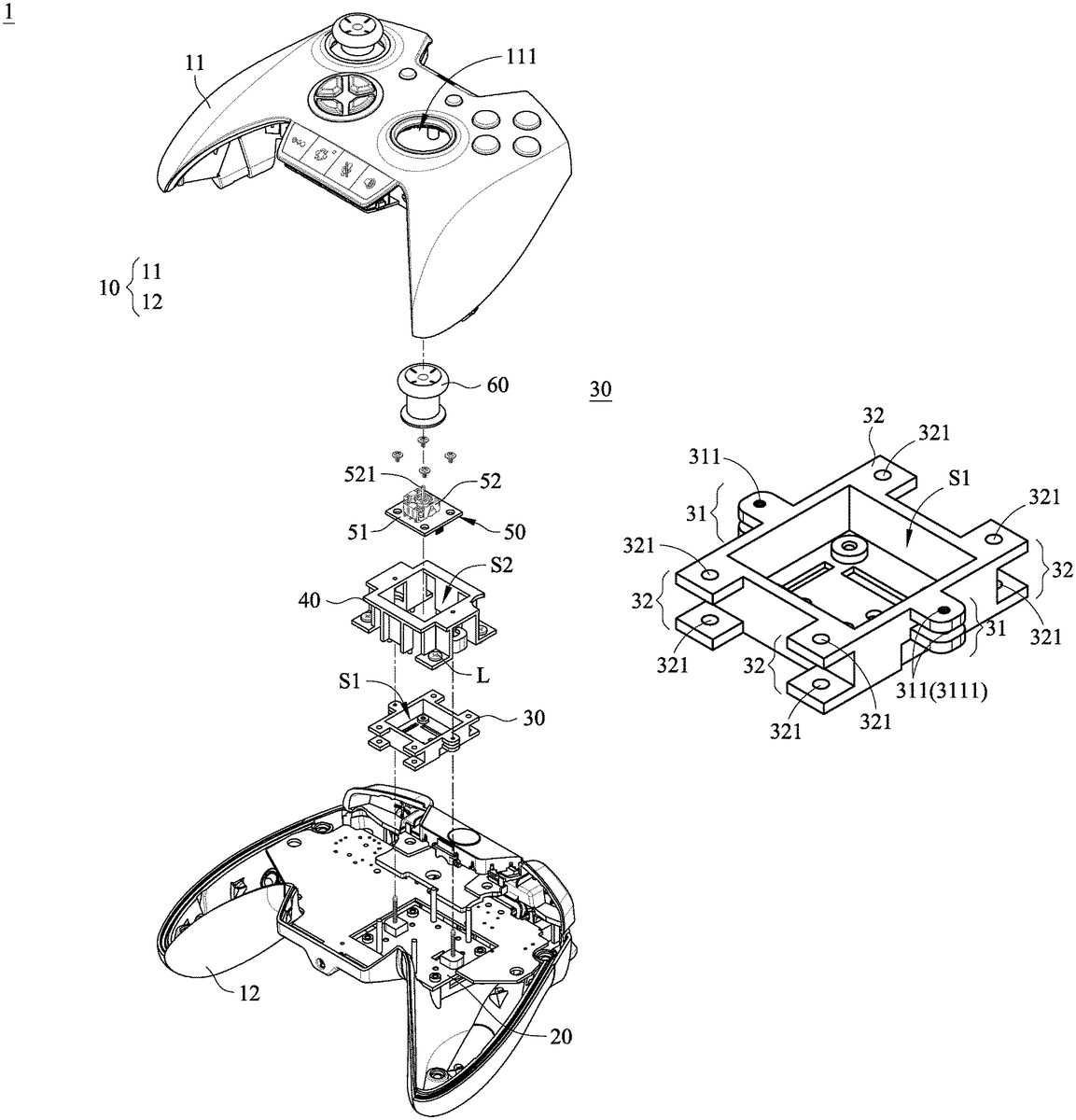
Please refer toFIG. 2.FIG. 2is a schematic explode view illustrating the game controller according to the embodiment of the present invention. As shown inFIG. 2, the game controller1further comprises a base20, a movable seat30, a position-limiting seat40and a signal control module50, which are disposed within an accommodation space between the upper cover11and the lower cover12. In an embodiment, the base20is combined with the position-limiting seat40and fixed on an inner surface of the lower cover12through fastening elements L (e.g., screws). The movable seat30is disposed within a receiving space S2of the position-limiting seat40and located over the base20. The signal control module50is disposed within an installation space S1of the movable seat30. In an embodiment, the signal control module50comprises a circuit board51and a controlling element52. The controlling element52is installed on the circuit board51. The controlling element52comprises a coupling part521. The coupling part521is connected with the operation element60. Consequently, a portion of the operation element60is exposed to the operation hole111and the operation element60is operable by the user's finger. When the operation element60is operated by the user, the signal control module50issues a corresponding control signal.
Please refer toFIG. 2andFIG. 3A.FIG. 3Ais a schematic perspective view illustrating the base of the game controller according to the embodiment of the present invention. As shown inFIG. 3A, the base20comprises a main body21, at least one driving module22and at least one first position-limiting structure23. The at least one driving module22and the at least one first position-limiting structure23are disposed on a surface of the main body21. In addition, the at least one driving module22is electrically connected with the adjusting switch121(seeFIG. 1B). In this embodiment, the base20comprises two driving assemblies22and four first position-limiting structures23. The two driving assemblies22are opposed to each other. Two of the four first position-limiting structures23are opposed to each other. The other two first position-limiting structures23are opposed to each other. The driving module22comprises a step motor221and a threaded rod222. The threaded rod222is connected with the step motor221. The threaded rod222has an external thread segment2221. By operating the up-switch part1211or the down-switch part122of the adjusting switch121, the step motor121is driven and controlled to rotate the threaded rod222in a clockwise direction or a counterclockwise direction.
In an embodiment, the first position-limiting structure23is a cylindrical support bar. Moreover, plural fastening holes211and plural main positioning holes212run through the main body21of the base20. In this embodiment, the plural fastening holes211are located at four corners of the main body21, respectively. Each main positioning hole212is arranged between the nearby driving module22and the nearby first position-limiting structure23or arranged between two adjacent first position-limiting structures23.
Please refer toFIG. 2andFIG. 3B.FIG. 3Bis a schematic perspective view illustrating the movable seat of the game controller according to the embodiment of the present invention. As shown inFIG. 3B, the movable seat30comprises the installation space S1, at least one linking part31and at least one second position-limiting structure32. The linking part31is connected with the corresponding driving module22. Each second position-limiting structure32cooperates with the corresponding first position-limiting structure23. Consequently, the movable seat30can be moved along the first position-limiting structures23. In this embodiment, the movable seat30comprises the two linking parts31and four second position-limiting structures32. The two linking parts31and the four second position-limiting structures32are protrusion ear structures that are externally extended from external surfaces of the movable seat30. The two linking parts31are disposed on a first lateral external surface and a second lateral external surface of the movable seat30, which are opposed to each other. Two of the four second position-limiting structures32are disposed on a third lateral external surface of the movable seat30, and the other two of the four second position-limiting structures32are disposed on a fourth lateral external surface of the movable seat30. The third lateral external surface and the four lateral external surface of the movable seat30are opposed to each other. The linking part31has two opposed threaded holes311corresponding to the threaded rod222(seeFIG. 3A). Each threaded hole311has an internal thread segment3111corresponding to the external thread segment2221of the threaded rod222. The second position-limiting structure32has two position-limiting holes321corresponding to the first position-limiting structure23(e.g., the support bar as shown inFIG. 3A).
Please refer toFIG. 2andFIG. 3C.FIG. 3Cis a schematic perspective view illustrating the position-limiting seat of the game controller according to the embodiment of the present invention. As shown inFIG. 3C, the position-limiting seat40comprises a top part41, a bottom part42and a lateral wall part43. The lateral wall part43is connected with the top part41and the bottom part42. The receiving space S2running through the top part41and the bottom part42is defined by the lateral wall part43. The top part41comprises at least one first positioning hole411and at least one second positioning hole412. The first positioning hole411runs through the top part41. The second positioning hole412is formed in an edge of a bottom side of the top part41. The first positioning hole411and the second positioning hole412are respectively aligned with the corresponding threaded rod222and the corresponding first position-limiting structure23(seeFIG. 3A). Moreover, four perforations421corresponding to the fastening holes211(seeFIG. 3A) are located at four corners of the bottom part42, and the bottom part42comprises plural main positioning posts422corresponding to the main positioning holes212(seeFIG. 3A).
Moreover, the lateral wall part43of the position-limiting seat40comprises two first pocket holes431and four second pocket holes433, which are open from the bottom part42to the top part41. The two first pocket holes431are opposed to each other. Two of the four second pocket holes433are opposed to each other. The other two second pocket holes433are opposed to each other. The first pocket holes431are respectively aligned with the corresponding linking parts31of the movable seat30(seeFIG. 3B). The second pocket holes433are respectively aligned with the corresponding second position-limiting structures32of the movable seat30(seeFIG. 3B). Moreover, the lateral wall part43of the position-limiting seat40further comprises two protective covers432. Each protective cover432is protruded from the lateral wall part43and located outside an end of the corresponding first pocket hole431near the bottom part42. The shape of the protective cover432matches the shape of the step motor221of the corresponding driving module22(seeFIG. 3A). After the associated components are assembled, the step motor221is covered and protected by the corresponding protective cover432.
FIG. 4is a schematic perspective view illustrating the assembled structure of a joystick device of the game controller according to the embodiment of the present invention. As shown inFIG. 4, the movable seat30is disposed within a receiving space S2of the position-limiting seat40. The two linking parts31are respectively inserted into the corresponding first pocket holes431. The four second position-limiting structures32are respectively inserted into the corresponding second pocket holes433. Each threaded rod222of the driving module22is penetrated through the corresponding two threaded holes311of the linking part31sequentially. An end of the threaded rod222away from the step motor221is penetrated through the corresponding first positioning hole411of the top part41of the position-limiting seat40. The external thread segment2221of the threaded rod222(seeFIG. 3A) and the internal thread segment3111of the corresponding threaded hole311(seeFIG. 3B) are engaged with each other. The first position-limiting structure23(i.e., the support bar) is penetrated through the corresponding two position-limiting holes321of the corresponding position-limiting structure32, respectively. An end of the first position-limiting structure23away from the main body21of the base20is inserted into the corresponding second positioning hole412.
The main positioning posts422of the position-limiting seat40(seeFIG. 3C) are penetrated through the corresponding main positioning holes212of the main body21(seeFIG. 3C). Consequently, the position-limiting seat40is positioned on the main body21. Then, fastening elements L are sequentially penetrated through the corresponding perforations421of the position-limiting seat40and the corresponding fastening holes211of the base20and tightened into the corresponding fastening holes211. Consequently, the base20and the position-limiting seat40are combined together, and the base20is fixed on the inner surface of the lower cover12(seeFIG. 2).
Please refer toFIGS. 1A, 1B, 5A and 5B.FIGS. 5A and 5Bare schematic perspective views illustrating the actions of adjusting the altitude of the joystick device of the game controller according to the embodiment of the present invention.
As shown inFIG. 5A, the movable seat30is in contact with the main body21of the base2. Meanwhile, the operation element60is located at the lowest altitude. If the user feels that the altitude of the operation element60is too low, the user may press the up-switch part1211of the adjusting switch121with the fingertip of the index finger or the middle finger. Please refer toFIG. 5B. After the up-switch part1211of the adjusting switch121is pressed, the step motor221is enabled to drive the rotation of the threaded rod222in the clockwise direction. As mentioned above, the external thread segment2221of the threaded rod222is engaged with the internal thread segments of the corresponding threaded holes311. Consequently, in response to the clockwise rotation of the threaded rod222, the linking part31is correspondingly moved and the movable seat30is moved upwardly through the linking part31. In other words, the movable seat30is gradually moved away from the main body21of the base2. Moreover, while the movable seat30is moved upwardly, the second position-limiting structures32are stopped by the top part41of the position-limiting seat40. Consequently, the movable range of the movable seat30is limited. As shown inFIG. 5B. The second position-limiting structures32of the movable seat30is in contact with the edges of the bottom side of the top part41. Meanwhile, the operation element60is ascended to the highest altitude.
On the other hand, if the user feels that the altitude of the operation element60is too high, the user may press the down-switch part1212of the adjusting switch121with the fingertip of the index finger or the middle finger. After the down-switch part1212of the adjusting switch121is pressed, the step motor221is enabled to drive the rotation of the threaded rod222in the counterclockwise direction. Consequently, in response to the counterclockwise rotation of the threaded rod222, the linking part31is correspondingly moved and the movable seat30is moved downwardly through the linking part31. In other words, the movable seat30is gradually moved away from the top part41of the position-limiting seat40.
In other words, the user may press the up-switch part1211or the down-switch part1212of the adjusting switch121to drive the step motor221. Consequently, the threaded rod222is rotated in the clockwise direction or the counterclockwise direction. As the movable seat30is moved with the linking part31upwardly or downwardly, the movable seat30can be maintained at any position between the top part41of the position-limiting seat40and the main body of the base2. Consequently, the altitude of the operation element60can be adjusted according to the practical requirements.
Moreover, since the movable seat30is moved along the threaded rod222in an engaged manner through the linking part31, the altitude of the operation element60can be finely tuned. In the above embodiment, the operation element60is a joystick. It is noted that the example of the operation element60is not restricted. For example, in another embodiment, the operation element60is a directional key or a button.
Please refer toFIG. 6.FIG. 6is a schematic perspective view illustrating a variant example of the base and the movable seat of the game controller according to the embodiment of the present invention. InFIG. 6, the structures and functions of the components of the base20and the movable seat30that are similar to the those ofFIGS. 3A and 3Bare not redundantly described herein. In comparison withFIGS. 3A and 3B, two opposed first position-limiting structures24and one driving module22are installed on the main body21of the base20. The first position-limiting structures24are position-limiting guide posts. The second position-limiting structures33are position-limiting recesses that are concavely formed in the external surface of the movable seat30. The cross section of the first position-limiting structure24and the cross section of the second position-limiting structure33have matching shapes. Consequently, the first position-limiting structure24is slidably engaged with the second position-limiting structure33. For example, the cross section of the first position-limiting structure24and the cross section of the second position-limiting structure33have semi-elliptic shapes or similar-circular shapes. The movable seat30is clamped by the two first position-limiting structures24. Consequently, during the engaged movement of the movable seat30, the movable seat30is not detached from the first position-limiting structures24.
Please refer toFIG. 7.FIG. 7is a schematic perspective view illustrating another variant example of the base and the movable seat of the game controller according to the embodiment of the present invention. InFIG. 7, the structures and functions of the components of the base20and the movable seat30that are similar to the those ofFIGS. 3A and 3Bare not redundantly described herein. In comparison withFIGS. 3A and 3B, one first position-limiting structure25and one driving module22are installed on the main body21of the base20. The first position-limiting structure25is also a position-limiting guide post. The second position-limiting structures34are also position-limiting recesses that are concavely formed in the external surface of the movable seat30. The cross section of the first position-limiting structure25and the cross section of the second position-limiting structure34have matching shapes. Consequently, the first position-limiting structure25is slidably engaged with the second position-limiting structure34. For example, the cross section of the first position-limiting structure25and the cross section of the second position-limiting structure34have trapezoid shapes. Consequently, during the engaged movement of the movable seat30, the movable seat30is not detached from the first position-limiting structures25.
From the above descriptions, the game controller1of the present invention is advantageous over the conventional technologies. By operating the adjusting switch121of the lower cover12, the altitude of the operation element60can be quickly and finely tuned according to the operation requirements of the user. When the game controller1is used by any user, the user may adjust the altitude of the operation element60according to the usual practice or the preference. Consequently, during the process of playing games with the game controller1, the satisfactory operating feel can be maintained. In other words, the technologies of the present invention are industrially valuable.
While the invention has been described in terms of what is presently considered to be the most practical and preferred embodiments, it is to be understood that the invention needs not be limited to the disclosed embodiments. On the contrary, it is intended to cover various modifications and similar arrangements included within the spirit and scope of the appended claims which are to be accorded with the broadest interpretation so as to encompass all such modifications and similar structures.
Claims
- A game controller, comprising: a casing comprising an upper cover and a lower cover, wherein at least one operation hole is formed in the upper cover;a base comprising a main body, at least one driving module and at least one first position-limiting structure, wherein the main body is fixed on an inner surface of the upper cover, the at least one driving module is installed on the main body, and the at least one first position-limiting structure is disposed on the main body;a movable seat disposed over the base, and comprising at least one linking part and at least one second position-limiting structure, wherein the at least one linking part is connected with the corresponding driving module, and the at least one second position-limiting structure cooperates with the corresponding first position-limiting structure, so that the movable seat is movable along the at least one first position-limiting structures;a signal control module installed on the movable seat;and an operation element connected with the signal control module, wherein a portion of the operation element is exposed to the at least one operation hole, wherein the at least one driving module drives a position-limiting movement of the movable seat relative to the base through the at least one linking part, so that an altitude of the operation element is adjustable, wherein the at least one linking part and least one second postion-limiting structure are protrusion ear structures that are externally extended from external surfaces of the movable seat, wherein each of the at least one linking part has two opposed threaded holes, and each of the at least one second position-limiting structure has two opposed position-limiting holes.
- The game controller according to claim 1 , wherein each of the at least one driving module comprises a step motor and a threaded rod, wherein the threaded rod is connected with the step motor, the threaded rod is penetrated through the two threaded holes sequentially, and an external thread segment of the threaded rod is engaged with internal thread segments of the two threaded holes, wherein the step motor drives rotation of the threaded rod, so that the threaded rod is moved in an engaged manner to drive the movement of the movable seat.
- The game controller according to claim 2 , wherein each of the at least one first position-limiting structure is a support bar, and the support bar is penetrated through the two position-limiting holes sequentially.
- The game controller according to claim 3 , wherein the game controller further comprises a position-limiting seat, and the position-limiting seat comprises a top part, a bottom part and a lateral wall part, wherein the lateral wall part is connected with the top part and the bottom part, a receiving space running through the top part and the bottom part is defined by the lateral wall part, the bottom part is connected with the main body of the base, and the movable seat is disposed within the receiving space.
- The game controller according to claim 4 , wherein the lateral wall part comprises at least one first pocket hole and at least one second pocket hole, which are open from the bottom part to the top part, wherein the at least one first pocket hole is aligned with the at least one linking part, and the at least one second pocket hole is aligned with the at least one second position-limiting structure, so that the at least one linking part is inserted into the at least one first pocket hole, and the at least one second position-limiting structure is inserted into the at least one second pocket hole.
- The game controller according to claim 5 , wherein the top part of the position-limiting seat comprises at least one first positioning hole corresponding to the at least one threaded rod and at least one second positioning hole corresponding to the support bar, wherein an end of the threaded rod away from the step motor is penetrated through the corresponding first positioning hole, and an end of the support bar way from the main body of the base is inserted into the corresponding second positioning hole.
- The game controller according to claim 6 , wherein the at least one second position-limiting structure is stopped by the top part of the position-limiting seat, so that a movable range of the movable seat is limited.
- The game controller according to claim 2 , wherein the lower cover comprises an adjusting switch, wherein by operating the adjusting switch to drive and control the step motor, the threaded rod is rotated in a clockwise direction or a counterclockwise direction.
- The game controller according to claim 1 , wherein the movable seat comprises an installation space, and the signal control module is installed within the installation space.
- The game controller according to claim 1 , wherein the signal control module comprises a circuit board and a controlling element, wherein the controlling element is installed on the circuit board, the controlling element comprises a coupling part, and the coupling part is connected with the operation element.
- The game controller according to claim 1 , wherein the operation element is a joystick, a directional key or a button.
- A game controller, comprising: a casing comprising an upper cover and a lower cover, wherein at least one operation hole is formed in the upper cover;a base comprising a main body, at least one driving module and at least one first position-limiting structure, wherein the main body is fixed on an inner surface of the upper cover, the at least one driving module is installed on the main body, and the at least one first position-limiting structure is disposed on the main body;a movable seat disposed over the base, and comprising at least one linking part and at least one second position-limiting structure, wherein the at least one linking part is connected with the corresponding driving module, and the at least one second position-limiting structure cooperates with the corresponding first position-limiting structure, so that the movable seat is movable along the at least one first position-limiting structures;a signal control module installed on the movable seat;and an operation element connected with the signal control module, wherein a portion of the operation element is exposed to the at least one operation hole, wherein the at least one driving module drives a position-limiting movement of the movable seat relative to the base through the at least one linking part, so that an altitude of the operation element is adjustable, wherein each of the at least one second position-limiting structure is a position-limiting recess that is concavely formed in an external surface of the movable seat.
- The game controller according to claim 12 , wherein each of the at least one first position-limiting structure is a position-limiting guide post, and a shape of a cross section of the position-limiting guide post matches a shape of a cross section of the corresponding position-limiting recess, so that the position-limiting guide post is slidably engaged with the corresponding position-limiting recess.
- The game controller according to claim 13 , wherein the cross section of the position-limiting guide post and the cross section of the corresponding position-limiting recess have semi-elliptic shapes, similar-circular shapes or trapezoid shapes.
Disclaimer: Data collected from the USPTO and may be malformed, incomplete, and/or otherwise inaccurate.